 | –≠–ª–µ–∫—Ç—Ä–æ–Ω–Ω—ã–π –∫–æ–º–ø–æ–Ω–µ–Ω—Ç: UTCTL072 | –°–∫–∞—á–∞—Ç—å:  PDF PDF  ZIP ZIP |

UTC TL072
LINEAR INTEGRATED CIRCUIT
UTC
UNISONIC TECHNOLOGIES CO., LTD.
1
QW-R105-004,B
LOW NOISE DUAL J-FET
OPERATIONAL AMPLIFIER
DESCRIPTION
The UTC TL072 is a high speed J-FET input dual
operational amplifier. It incorporates well matched,
high voltage J-FET and bipolar transistors in a
monolithic integrated circuit. The device features high
slew rates, low input bias and offset current, and low
offset voltage temperature coefficient.
FEATURES
*Low power consumption
*Wide common-mode (up to v
cc
+
) and differential
voltage range
*Low input bias and offset current
*Low noise e
n
= 15nV /
Hz (typ)
*Output short-circuit protection
*High input impedance J-FET input stage
*Low harmonic distortion:0.01%(typ)
*Internal frequency compensation
*Latch up free operation
*High slewrate:16V/
µs(typ)
DIP-8
SOP-8
TSSOP-8
PIN CONFIGURATIONS
1
2
3
4
8
7
6
5
OUTPUT 1
INVERTING
INPUT 1
NON-
INVERTING
INPUT 1
Vcc-
Vcc+
OUTPUT 2
INVERTING
INPUT 2
NON-
INVERTING
INPUT 2

UTC TL072
LINEAR INTEGRATED CIRCUIT
UTC
UNISONIC TECHNOLOGIES CO., LTD.
2
QW-R105-004,B
BLOCK DIAGRAM
ABSOLUTE MAXIMUM RATINGS
(Ta=25
∞C )
PARAMETER
SYMBOL
VALUE
UNIT
Supply Voltage (note 1)
Vcc
+-18
V
Input Voltage (note 2)
Vi
+-15
V
Differential Input Voltage (note 3)
Vid
+-30
V
Power Dissipation
Ptot
680
mW
Output Short-Circuit Duration (Note 4)
Infinite
Operating Free Air Temperature Range
Toper
0 to 70
∞C
Storage Temperature Range
Tstg
-65 to 150
∞C
NOTES: 1. All voltage values, except differential voltage, are with respect to the zero reference level
(ground) of the supply voltages where the zero reference level is the midpoint between Vcc-
and Vcc+.
2. The magnitude of the input voltage must never exceed the magnitude of the supply voltage
or 15 volts, whichever is less.
3. Differential voltages are at the non-inverting input terminal with respect to the inverting input
terminal.
4. The output may be shorted to ground or to either supply. Temperature and/or supply
voltages must be limited to ensure that the dissipation rating is not exceeded.
UTC TL072
LINEAR INTEGRATED CIRCUIT
UTC
UNISONIC TECHNOLOGIES CO., LTD.
3
QW-R105-004,B
UTC TL072 C ELECTRICAL CHARACTERISTICS
( Vcc=+-15V, Ta=25
∞C,
Tmin=0
∞C
,Tmax=70
∞C
, unless otherwise specified)
PARAMETER
SYMBOL
MIN
TYP
MAX
UNIT
Input Offset Voltage (Rs=50
, Ta=25∞C
Tmin<=Ta<=Tmax
Vio 3
10
13
mV
Temperature Coefficient of Input Offset
Voltage (Rs=50
)
Dvio 10
µV/∞C
Input Offset Current*
Ta=25
∞C
Tmin<=Ta<=Tmax
Iio
5
100
10
Pa
nA
Input Bias Current*
Ta=25
∞C
Tmin<=Ta<=Tmax
Iib
20
200
20
pA
nA
Input Common Mode Voltage
Vicm
+-11
-12~+15
V
Output Voltage Swing (R
L
=10k
)
Ta=25
∞C, R
L
=2k
,
Ta=25
∞C, R
L
=10k
Tmin<=Ta<=Tmax, R
L
=2k
Tmin<=Ta<=Tmax, R
L
=10k
Vopp
10
12
10
12
12
13.5
V
Large Signal Voltage Gain (R
L
=10k
,
Vo=+-10V) Ta=25
∞C
Tmin<=Ta<=Tmax
Avd
25
15
200
V/mV
Gain Bandwidth Product (Ta=25
∞C,
R
L
=10k
, C
L
=100pF)
GBP 2.5 4 MHz
Input Resistance
Ri
10
12
Common Mode Rejection Ratio (R
S
=50
)
Ta=25
∞C
Tmin<=Ta<=Tmax
CMR
70
70
86
dB
Supply Voltage Rejection Ratio (R
S
=50
)
Ta=25
∞C
Tmin<=Ta<=Tmax
SVR
70
70
86
dB
Supply Current( no load)
Ta=25
∞C
Tmin<=Ta<=Tmax
Icc
1. 4
2. 5
2.5
mA
Channel Separation (Av=100, Ta=25
∞C)
V
01
/V
02
120 dB
Output Short-circuit Current
Ta=25
∞C
Tmin<=Ta<=Tmax
Ios
10
10
40
60
60
mA
Slew Rate (Vi=10V, R
L
=2k
, C
L
=100pF,
Ta=25
∞C, unity gain)
SR 8
16
V/
µs
Rise Time (Vi=20mV, R
L
=2k
, C
L
=100pF,
Ta=25
∞C, unity gain)
t
r
0.1 µs
Overshoot Factor (Vi=20mV, R
L
=2k
,
C
L
=100pF, Ta=25
∞C, unity gain)
Kov 10 %
Total Harmonic Distortion (Av=20dB, f=1kHz
R
L
=2k
, C
L
=100pF, Ta=25
∞C, Vo=2Vpp)
THD
0.01
%
Phase Margin
m
45
Degrees
Equivalent Input Noise Voltage(R
S
=100
,
f=1KHz)
e
n
15 nV
Hz
*The Input bias currents are junction leakage currents, which approximately double for every 10
∞C increase
in the junction temperature.
UTC TL072
LINEAR INTEGRATED CIRCUIT
UTC
UNISONIC TECHNOLOGIES CO., LTD.
4
QW-R105-004,B
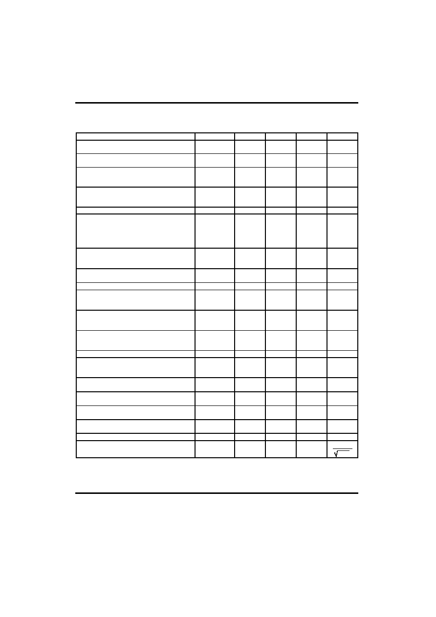
UTC TL072 AC ELECTRICAL CHARACTERISTICS
( Vcc=+-15V, Ta=25
∞C,
Tmin=0
∞C
,Tmax=70
∞C,
unless otherwise specified)
PARAMETER
SYMBOL
MIN
TYP
MAX
UNIT
Input Offset Voltage (Rs=50
, Ta=25∞C
Tmin<=Ta<=Tmax
Vio 3
6
7
mV
Temperature Coefficient of Input Offset
Voltage (Rs=50
)
Dvio 10
µV/∞C
Input Offset Current*
Ta=25
∞C
Tmin<=Ta<=Tmax
Iio
5
100
4
pA
nA
Input Bias Current*
Ta=25
∞C
Tmin<=Ta<=Tmax
Iib
20
200
20
pA
nA
Input Common Mode Voltage
Vicm
+-11
-12~+15
V
Output Voltage Swing (R
L
=10k
)
Ta=25
, R
L
=2k
,
Ta=25
∞C, R
L
=10k
Tmin<=Ta<=Tmax, R
L
=2k
Tmin<=Ta<=Tmax, R
L
=10k
Vopp
10
12
10
12
12
13.5
V
Large Signal Voltage Gain (R
L
=10k
,
Vo=+-10V) Ta=25
∞C
Tmin<=Ta<=Tmax
Avd
50
25
200
V/mV
Gain Bandwidth Product (Ta=25
∞C,
R
L
=10k
, C
L
=100pF)
GBP 2.5 4 MHz
Input Resistance
Ri
10
12
Common Mode Rejection Ratio (R
S
=50
)
Ta=25
∞C
Tmin<=Ta<=Tmax
CMR
80
80
86
dB
Supply Voltage Rejection Ratio (R
S
=50
)
Ta=25
∞C
Tmin<=Ta<=Tmax
SVR
80
80
86
dB
Supply Current (no load)
Ta=25
∞C
Tmin<=Ta<=Tmax
Icc
1. 4
2. 5
2.5
mA
Channel Separation (Av=100, Ta=25
∞C)
V
01
/V
02
120 dB
Output Short-circuit Current
Ta=25
∞C
Tmin<=Ta<=Tmax
Ios
10
10
40
60
60
mA
Slew Rate (Vi=10V, R
L
=2k
, C
L
=100pF,
Ta=25
∞C, unity gain)
SR 8
16
V/
µs
Rise Time (Vi=20mV, R
L
=2k
, C
L
=100pF,
Ta=25
∞C, unity gain)
t
r
0.1 µs
Overshoot Factor (Vi=20mV, R
L
=2k
,
C
L
=100pF, Ta=25
∞C, unity gain)
Kov 10 %
Total Harmonic Distortion (Av=20dB, f=1kHz
R
L
=2k
, C
L
=100pF, Ta=25
∞C, Vo=2Vpp)
THD
0.01
%
Phase Margin
m
45
Degrees
Equivalent Input Noise Voltage (R
S
=100
,
f=1KHz)
e
n
15 nV
Hz
*The Input bias currents are junction leakage currents, which approximately double for every 10
∞C increase
in the junction temperature.

UTC TL072
LINEAR INTEGRATED CIRCUIT
UTC
UNISONIC TECHNOLOGIES CO., LTD.
5
QW-R105-004,B
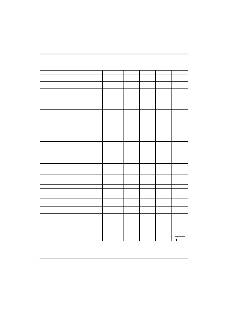
UTC TL072 BC ELECTRICAL CHARACTERISTICS
( Vcc=+- 15V, Ta=25
∞C
,
Tmin=0
∞C
,Tmax=70
∞C,
unless otherwise specified
unless otherwise specified)
PARAMETER
SYMBOL
MIN
TYP
MAX
UNIT
Input Offset Voltage (Rs=50
), Ta=25∞C
Tmin<=Ta<=Tmax
Vio 1
3
5
mV
Temperature Coefficient of Input Offset
Voltage (Rs=50
)
Dvio 10
µV/
Input Offset Current*
Ta=25
∞C
Tmin<=Ta<=Tmax
Iio
5
100
4
pA
nA
Input Bias Current*
Ta=25
∞C
Tmin<=Ta<=Tmax
Iib
20
200
20
pA
nA
Input Common Mode Voltage
Vicm
+-11
-12~+15
V
Output Voltage Swing (R
L
=10k
)
Ta=25
∞C, R
L
=2k
Ta=25
∞C, R
L
=10k
Tmin<=Ta<=Tmax, R
L
=2k
Tmin<=Ta<=Tmax, R
L
=10k
Vopp
10
12
10
12
12
13.5
V
Large Signal Voltage Gain (R
L
=10k
,
Vo=+-10V) Ta=25
∞C
Tmin<=Ta<=Tmax
Avd
50
25
200
V/mV
Gain Bandwidth Product (Ta=25
∞C,
R
L
=10k
, C
L
=100pF)
GBP 2.5 4 MHz
Input Resistance
Ri
10
12
Common Mode Rejection Ratio (R
S
=50
)
Ta=25
∞C
Tmin<=Ta<=Tmax
CMR
80
80
86
dB
Supply Voltage Rejection Ratio (R
S
=50
)
Ta=25
∞C
Tmin<=Ta<=Tmax
SVR
80
80
86
dB
Supply Current ( no load)
Ta=25
∞C
Tmin<=Ta<=Tmax
Icc
1. 4
2. 5
2.5
mA
Channel Separation (Av=100, Ta=25
∞C)
V
01
/V
02
120 dB
Output Short-circuit Current
Ta=25
∞C
Tmin<=Ta<=Tmax
Ios
10
10
40
60
60
mA
Slew Rate (Vi=10V, R
L
=2k
, C
L
=100pF,
Ta=25
∞C, unity gain)
SR 8
16
V/
µs
Rise Time (Vi=20mV, R
L
=2k
, C
L
=100pF,
Ta=25
∞C, unity gain)
t
r
0.1 µs
Overshoot Factor (Vi=20mV, R
L
=2k
,
C
L
=100pF, Ta=25
∞C, unity gain)
Kov 10 %
Total Harmonic Distortion (Av=20dB, f=1kHz
R
L
=2k
, C
L
=100pF, Ta=25
∞C, Vo=2Vpp)
THD
0.01
%
Phase Margin
m
45
Degrees
Equivalent Input Noise Voltage (R
S
=100
,
f=1KHz)
e
n
15 nV
Hz
*The Input bias currents are junction leakage currents, which approximately double for every 10
∞C increase
in the junction temperature.