V C X O
VF960/961
75 South Street, Hopkinton, MA 01748 800-982-5737 508-435-6831 Fax: 508-435-5289 www.valpeyfisher.com
80
VF960/VF961
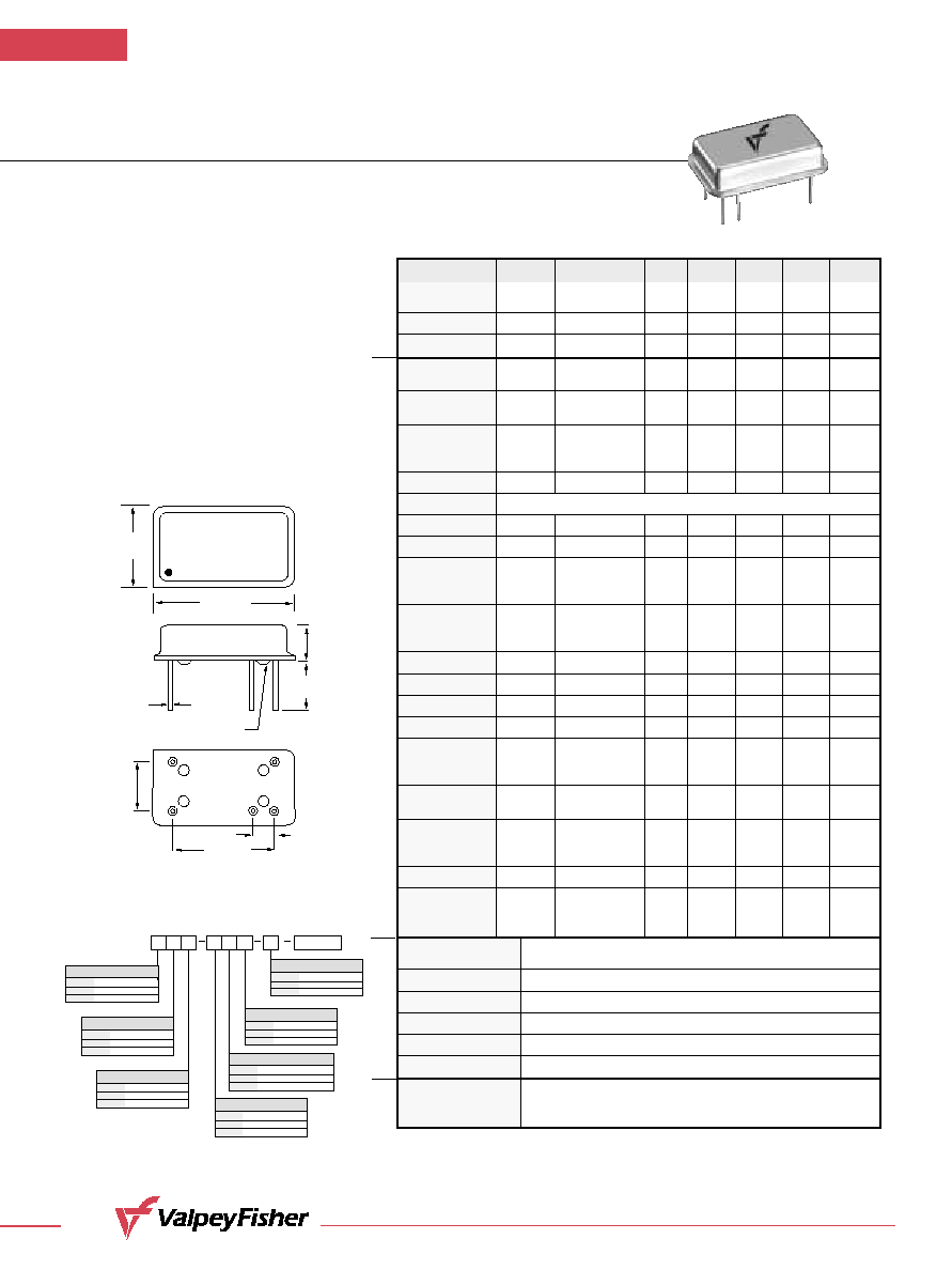
ECL/PECL Compatible Hybrid VCXO
Standard 14 Pin DIP Package
F E AT U R E S
∑
No Frequency Multiplication is Used
∑
Very Low Phase Jitter
∑
Low Component Count
∑
Pullability (±500 ppm available)
∑
Temperature Range
(≠40∞C to +85∞C) Available
∑
Complementary Output Available
∑
Wide Frequency Range
0.300"
(7,62mm)
0.600"
(15,24mm)
.187"
(4,75mm)
0.100"
(2,54mm)
GLASS STANDOFFS
¯0.0180"
(0,460mm)
0.800"
(20,32mm)
0.497"
(12,62mm)
VALPEYFISHER
VF961
155.52MHZ
BO1H
#1
#7
#8
#14
#9
*
0.250"
(6,35mm)
Creating a Part Number
VF960/961
LEAD CONFIGURATION
Code
Specification
G
Gull Wing
Through Hole (std.)
INPUT VOLTAGE
Code
Specification
L 3.3
Volt
±
5%*
5.0
Volt
±
5% (std.)
OPERATIONAL TEMP. RANGE
Code
Specification
0
∞
C to +70
∞
C (std.)
1 -40
∞
C to +85
∞
C
FREQUENCY STABILITY
Code
Specification
S
±
20 ppm
±
25
ppm (std.)
ABSOLUTE PULL RANGE (ppm)
Code
Specification
±
50 ppm MIN. (std.)
XXX
up to 500 ppm
(customer specified)
OUTPUT
Code
Specification
C
Complementary
4 pin pkg Single (std.)
(*VF961 Only)
DUTY CYCLE
Code
Specification
H
±
5%
±
10% (std.)
Example: VF960SHL-1CG-100-106.25MHz: Frequency Stability
±
20ppm,
Duty Cycle
±
5%, Input Voltage 3.3 Volt
±
5%, Operating Temperature
-40
∞
C to +85
∞
C, Complementary Output (5-pin package), Gull Wing,
APR
±
100ppm, Frequency 106.25MHz.
FREQ.
Parameter
Symb
Condition
Min
Typ
Max
Unit
Note
Input Break
Vcc≠Vee
≠.5
7.0
V
Down Voltage
Storage Temp.
Ts
≠40
+85
∞C
Control Voltage
Vc
≠1.0
9.0
V
Frequency
Range
F
10
200
MHz
Frequency
F/F
Over Temp, Vcc
±25
ppm
Stability
Input Voltage
Vcc
PECL
4.75
5.00
5.25
VF961
Vee
ECL
≠4.95
≠5.20
≠5.45
VF960
Vcc
LVPECL
3.15
3.30
3.45
VF961L
Input Current
Icc/Iee
50 Ohm Load
65
mA
Load
Duty Cycle
@50%
40
50
60
%
1
Rise/Fall Time
Tr/Tf
20% to 80%
1.5
ns
Logic "1" Level
Voh
@Vcc = 5.0V
4.04
4.19
V
PECL
@Vee = ≠5.2V
≠0.96
≠0.81
ECL
@Vcc = 3.3V
2.59
2.74
LVPECL
Logic "0" Level
Vol
@Vcc = 5.0V
3.15
3.25
V
PECL
@Vee = ≠5.2V
≠1.85
≠1.65
ECL
@Vcc = 3.3V
1.45
1.55
LVPECL
Start≠up Time
Ts
2
10
ms
Phase Jitter
1
1
ps
fj>1KHz
Modulation BW
fm
@ Vc = 2.5V
10
KHz
@≠3db
Input Impedance
fm<10KHz
50
KOhm
Control Voltage
Vc
PECL
0.0
5.0
V
2
ECL
≠5.0
0.0
LVPECL
0.0
3.3
Absolute
APR
Overall
±50
ppm
3
Pull Range
Deviation Slope
Monotonic, pos.
50
ppm/V
PECL
Monotonic, neg.
≠50
ECL
Monotonic, pos.
75
LVPECL
Linearity ±20
%
4
Setability (Vc
Vc0
@25∞C, Fnominal 2.00
2.50
3.00
V
PECL
for center freq)
≠2.00 ≠2.50
≠3.00
ECL
1.25 1.65
2.05
LVPECL
Operating
Temperature Range
0∞C to +70∞C (≠40∞C to +85∞C available)
Mechanical Shock
Per MIL≠STD≠202, Method 213, Cond. E
Thermal Shock
Per MIL≠STD≠883, Method 1011, Cond. A
Vibration
Per MIL≠STD≠883, Method 2007, Cond. A
Soldering Conditions
260∞C, for 10s, Max.
Hermetic Seal
Leak rate less than 5 x 10
≠8
atm.cc/s of helium
Pin Out
Pin #1≠Voltage Control
Pin #7≠Ground, Case (PECL)/≠Vee(ECL)
Pin #8≠Output
Pin #14≠Vcc (PECL)/Case,Ground (ECL)
Pin #9≠Complementary Output (Optional)
50 Ohm to Vcc≠2V or Thevenin Equiv. Bias required
Absolute
Max. Ratings
Electrical
Environmental and Mechanical
Electrical
Connections Notes:
1. Tighter duty cycle available.
2. 0V to 5V control voltage available for Vcc 3.3V. Nominal control voltage is 2.5V
and setability is ±0.5V in this case.
3. Wider pullability available.
4. 10% and 5% available.
All dimensions are typical unless otherwise specified.
* Pin 9 optional