Features
∑ Output frequencies up to 170 MHz
∑ Jitter Generation OC-192 compliant
∑ Jitter transfer per GR-253-CORE
∑ Single 5 or 3.3 Vdc supply
∑ Locked to specified Input frequency, e.g. 8 kHz
∑ 1" x 0.8" x 0.25", Surface Mount (FR4 base)
Applications
∑ SONET / SDH / ATM
∑ DWDM / FDM
∑ DSL-PON Interconnects
∑ FEC (Forward Error Correction)
Product Data Sheet
FX-102
Frequency Translator

FX-102 Frequency Translator
Vectron International ∑
267 Lowell Road, Hudson, NH 03051 ∑ Tel:
1-88-VECTRON-1 ∑ Web:
www.vectron.com
Performance Characteristics
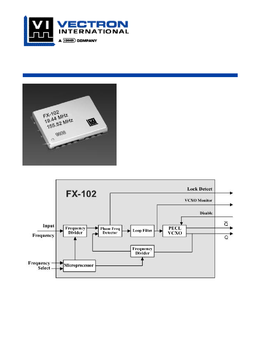
Description
Vectron's FX-102 is a crystal based frequency tra n s l a t o r
which is used to translate any input frequency such as 8
kHz, 1.544 MHz, 2.048 MHz, 19.440 MHz etc. to any
specific frequency from 77.76 to 170 MHz. The input
frequency does not have to be a 50/50% duty cycle and
as an example can be an 8 kHz signal with a logic high
"on time" of only 1us, such as a BITS clock . The FX-102
also has the ability to translate any of 1 to 4 diffe r e n t
input frequencies to one common output frequency,
such as input frequencies of 8 kHz and 1.544 MHz and
19.44 MHz and any other frequency between 8 kHz and
170 MHz translating them to any specific output fre-
quency from 77.76 MHz to 170 MHz.
The "Input Frequency tra cking capability" is the total
amount of input frequency deviation in which the FX-102
is guaranteed to tra ck or tra n s l a t e. As an ex a m p l e, a typ-
ical input clock would be 8 kHz ±20 ppm.The FX-102 is
g u a ranteed to tra ck at least ±40 ppm of error ove r
t e m p e rature/ aging/ power supply and is more than twice
what most applications require. The PLL control vo l t a g e
is brought out through a 470K ohm resistor. This wo u l d
a l l ow for the use of ex t e rnal circuitry (analog compara-
tors or an A/D conve rter plus a processor) to detect
when the control voltage is getting close to the limits of
the pull ra n g e.
Output Frequencies
77.76
170
MHz
Supply Voltage,
C = 5 Vdc
V
cc
4.75
5.00
5.25
Vdc
D = 3.3 Vdc
V
cc
3.15
3.30
3.45
Vdc
Supply Current
I
cc
75
100
mA
Input Signal,
A = HCMOS
CLKIN
HCMOS
D = PECL
CLKIN
PECL
---
---
OUTPUT,
F = Comp PECL
---
---
PECL
---
---
V
OH
(Temp Range C = 0∞C to +70∞C)
V
OH
V
cc
-1.025
V
cc
-0.880
V
V
OL
(Temp Range C = 0∞C to +70∞C)
V
OL
V
cc
-1.810
V
cc
-1.620
V
V
OH
(Temp Range F = -40∞C to +85∞C)
V
OH
V
cc
-1.085
V
cc
-0.880
V
V
OL
(Temp Range F = -40∞C to +85∞C)
V
OL
V
cc
-1.830
V
cc
-1.555
V
Rise/Fall Time
t
R
/t
F
0.5
1
ns
Output Symmetry
Sym
45
55
%
Jitter Generation, rms
(12 kHz to 20 MHz)
<0.5
1
ps
Jitter Generation, rms
(cycle to cycle method)
3
5
ps
Jitter Transfer, GR-253-CORE sec 5.6.2.1.2
0.1
dB
Input Frequency Tracking Capability
(Can translate a Stratum 1,2,3,3E,4
APR
±40
ppm
or SONET Min source)
Operating Temperature
Temp Range C = 0∞C to +70∞C
Temp Range F = -40∞C to +85∞C
Size
25.4 x 20.32 x 6.35 mm (1.0" x 0.8" x 0.25")
Parameter
Symbol
Min
Typical
Max
Unit
Vectron International ∑
267 Lowell Road, Hudson, NH 03051∑ Tel:
1-88-VECTRON-1 ∑ Web:
www.vectron.com
FX-102 Frequency Translator
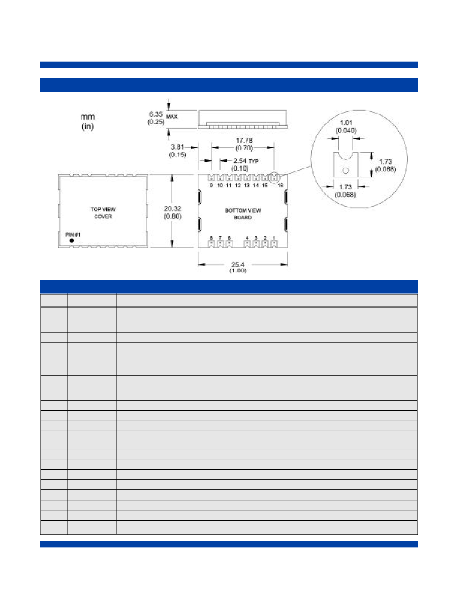
Outline Drawing
Pin
Symbol
Function
1
CLKIN
Input Frequency - The FX-102 series AC couples the input, this means the unit is capable of
handling HCMOS, LvHCMOS, PECL and LvPECL input signals.
(For Input Frequencies below1 MHz only HCMOS and LvHCMOS are supported.)
2
GND
Ground
3
LD
Lock Detect
(output)
Logic "1" indicates a locked condition
Logic "0" indicates that no input signal is present or the input signal has moved out of the
lock range.
4
Monitor
PLL/ VCXO control voltage
(Output)
Under locked conditions, should be >0.3V and <3.0V for the 3.3 volt option or >0.5V and
<4.5V for the 5 volt option. Input frequency may be out of range if voltage exceeds these limits.
5
---
Missing
6
NC
No Connection
7
GND
Ground
8
Enable /
Logic "0" (or no connect) = Output Enabled
Disable
Logic "1"
= Output Disabled
9
Out
Output
10
COut
Complementary Output
11
NC
No Connection
12
Select A
Do not Exceed Vcc
13
Select B
Do not Exceed Vcc
14
NC
No Connection
15
GND
Ground
16
V
cc
Power Supply Voltage (5 Vdc or 3.3Vdc)
Pin Out
FX-102 Frequency Translator
Vectron International ∑
267 Lowell Road, Hudson, NH 03051 ∑ Tel:
1-88-VECTRON-1 ∑ Web:
www.vectron.com
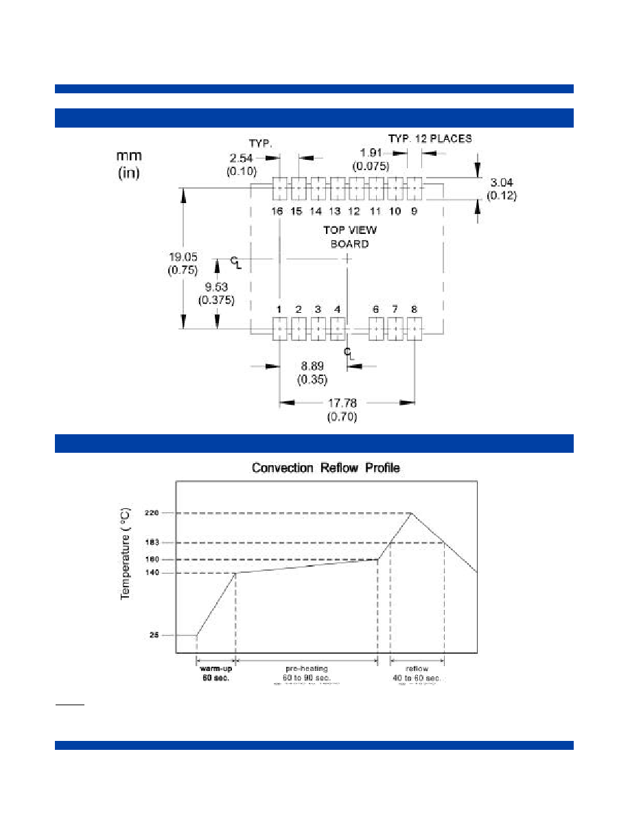
Pad Layout
Recommended Reflow Profile
NOTE: The FX-100 series should not be subjected to a wash process that will immerse it in solvents. NO CLEAN is the rec-
ommended procedure. The FX-100 series has been designed for pick and place reflow soldering. The suggested reflow pro-
file is shown above. The FX-100 series may be reflowed once, and should not be reflowed in the inverted position.

Vectron International ∑
267 Lowell Road, Hudson, NH 03051 ∑ Tel:
1-88-VECTRON-1 ∑ Web:
www.vectron.com
FX-102 Frequency Translator
Standard Shipping Method
The Standard ship method for volume production of the
FX-100 series is in a matrix tray. These trays are 100%
recyclable. The trays also offer the added feature that
they can be continuously feed into a pick-n-place
machine eliminating the down time required with tape-
n-reel.
Handling Precautions
Although protection circuitry has been designed into this
d ev i c e, proper precautions should be taken to avoid ex p o-
sure to electrostatic discharge (ESD) during handling and
m o u n t i n g . VI employs a human-body model (HBM) fo r
ESD-susceptibility testing and protection design eva l u a-
t i o n .
ESD voltage thresholds are dependent on the circuit para-
meters used to define the mode. The HBM ESD thresh-
old presented here was obtained by using para m e t e r s
where resistance = 1500 ohms, capacitance = 100pf)
ESD Threshold Voltage
Model
Threshold
Unit
Human Body (HBM)
500
V min
FX-102 Frequency Translator
Vectron International ∑
267 Lowell Road, Hudson, NH 03051 ∑ Tel:
1-88-VECTRON-1 ∑ Web:
www.vectron.com
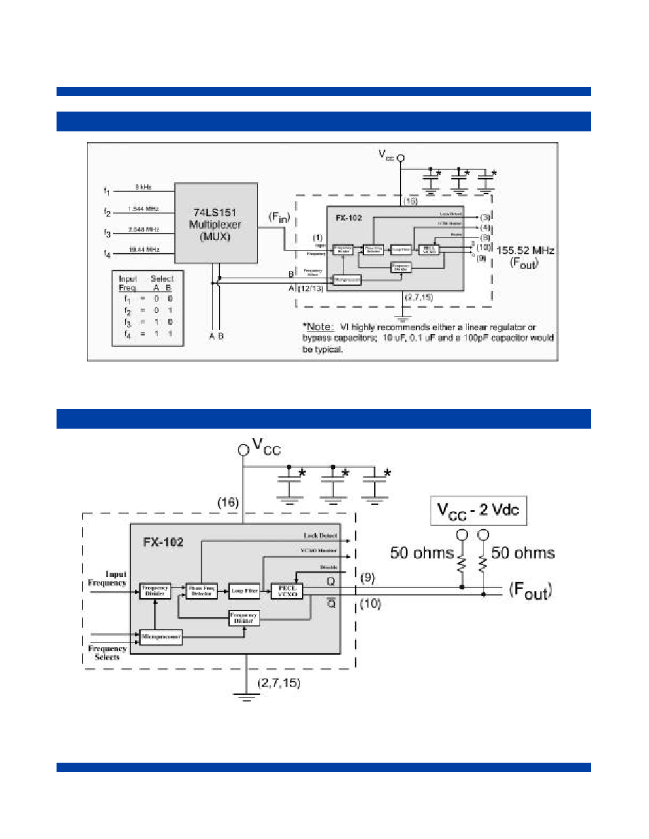
All components outside the dotted line box are user supplied components. This is just one possbile
configuration of the FX-102. For additional information about your specific needs, please contact our factory.
Typical Application
Output Load Configuration
*Note: VI highly recommends either a linear
regulator or bypass capacitors; 10 uF, 0.1 uF
and a 100pF capacitor would be typical.
All components outside the dotted line box are user supplied components
and/or connections. This is just one possible configuration of the FX-102.
For additional information about your specific needs please contact our Factory.

Vectron International ∑
267 Lowell Road, Hudson, NH 03051 ∑ Tel:
1-88-VECTRON-1 ∑ Web:
www.vectron.com
FX-102 Frequency Translator
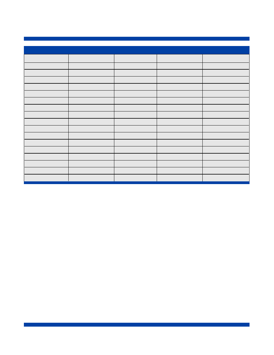
FX-100 Series Selection Guide
FITS / MTBF Calculations
Per Bellcore TR-NWT-000332, GF @ +50∫C.
Typical - FX-102-DFC-A1P6
FITs = 485.63
MTBF (Hours) = 2,059,202

FX-102 Frequency Translator
Vectron International ∑
267 Lowell Road, Hudson, NH 03051 ∑ Tel:
1-88-VECTRON-1 ∑ Web:
www.vectron.com
FAQ's
Q: What are the different input frequencies that are available?
A: The FX-100 series is able to handle any input frequency between 8 kHz and 170 MHz.
(A list of standard frequencies is available on pages 9 & 10.)
Q: How many different input frequencies can a specific FX-102 accept?
A: Each FX-102 can be programmed to accept up to 4 different frequencies.
Q: If there is only one input pin, how can your unit accept 4 different frequencies?
A: The user is required to supply a multiplexer which would switch between the different input
frequencies.The multiplexers' select pins would need to be sync'd to the select pins of the FX-102.
(See The Typical Application illustrated on page 6.)
Q: Can a single FX-102 handle an application for 4 input frequencies of 8 kHz, 19.44, 77.76 and 155.52 MHz
all being translated to 155.52 MHz, with the 155.52 MHz input being LvPECL and the others HCMOS?
A: Yes; since the FX-102 AC couples the input signal, this combination can be supported.
Q: What is the lock time for the FX-102?
A: The exact lock time will depend on the specific input frequency. It should be noted that in all cases
the lock time will be significantly less than 1 second.
Q: I asked for a FX-102-DFC-A2S6 with 19.44 and 155.52 MHz for the input frequencies and was given a
Source Control Drawing (SCD) number of FX-102-DFC-S5999. Why was a new number assigned?
A: Whenever there are multiple input frequencies, we need to assign a SCD for the unit so that we can
include a table indicating what the logic levels need to be on pins 12 and 13 to control the unit per
the correct input frequency.
Q: What are the exact jitter transfer specs that the FX-102 series meets?
A: The FX-102 meets the stringent jitter transfer specs in GR-253 for Category II jitter (Section 5.6.2.1.2)
for all OC-n levels.
Q: My circuit card is already laid out for the FX-104, Is the FX-102 footprint compatible?
A: Yes;The FX-102 package is a drop in replacement for the FX-104 package. The only difference is in
the logic level for the Output Disable/Enable pin. They are opposite between the FX-102 and FX-104.
However letting pin 8 float will allow both units to be enabled.
Q: What type of noise on the supply line can the FX-102 suppress?
A: The FX-102 is designed to clean up noise on the Input Clock Signal, it is not designed to clean up
noisy power supplies. If excessive noise is present on the supply line it may degrade the output jitter
performance. Additional external filtering may be required. Please consult with your power supply
vendor on the best way to filter noise on your supply line.
Vectron International ∑
267 Lowell Road, Hudson, NH 03051 ∑ Tel:
1-88-VECTRON-1 ∑ Web:
www.vectron.com
FX-102 Frequency Translator
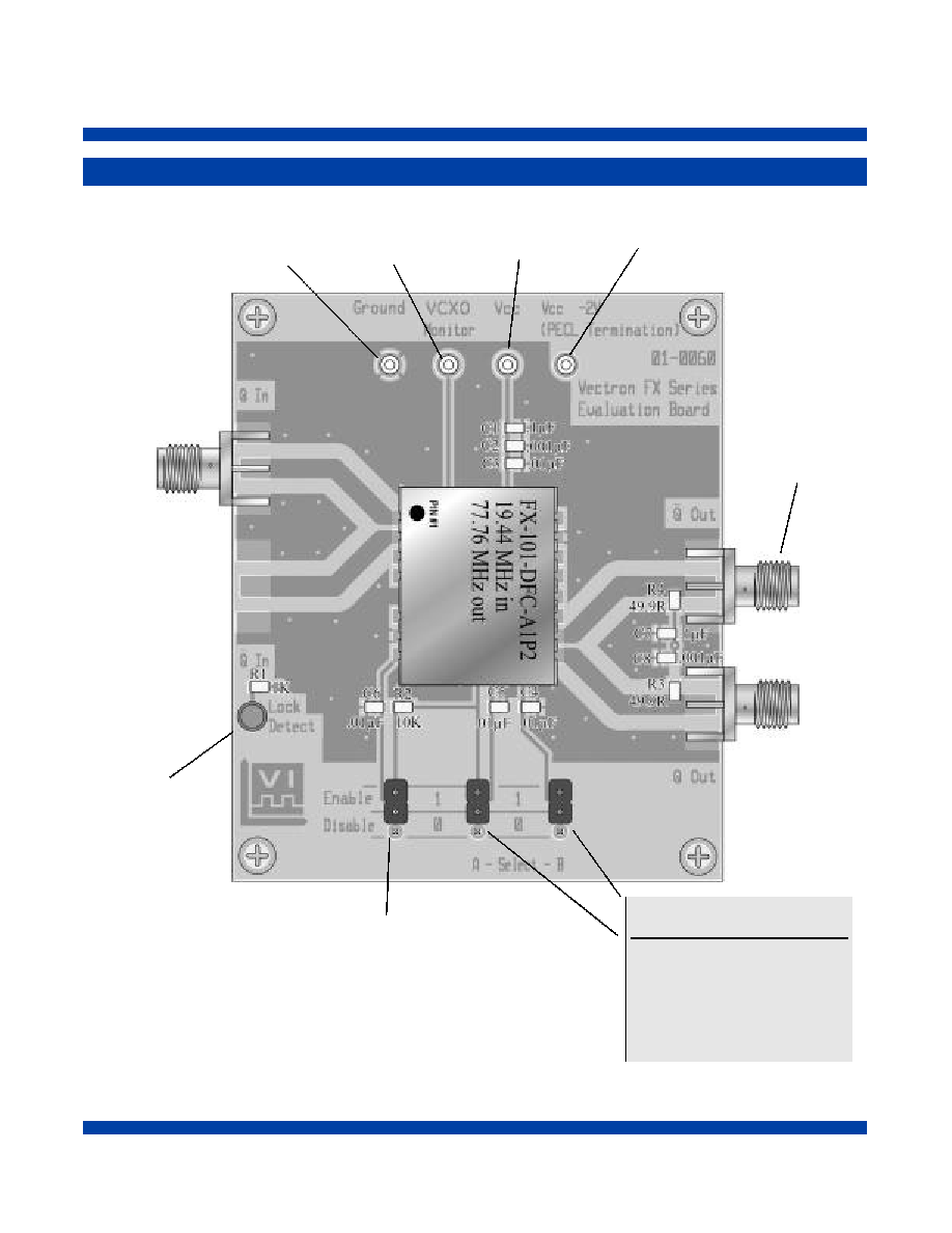
Evaluation Board
Evaluation boards are available upon request.
LED
Lights
Up
When
Locked
Input
Frequency
Edge
Mount
SMA
3 Places
Output
Frequency
PECL Load Voltage:
Vcc- 2V
For FX-101 with PECL output
Place Connector in the
"0" position for Enable
"1" position Disable
(In disable position as shown)
Input
Select
Freq.
A
B
f1
=
0
0
f2
=
0
1
f3
=
1
0
f4
=
1
1
VCXO
Monitor
Supply
Voltage
Ground
FX-102 Frequency Translator
Vectron International ∑
267 Lowell Road, Hudson, NH 03051 ∑ Tel:
1-88-VECTRON-1 ∑ Web:
www.vectron.com
Input 1
Input 2
Input 3
Input 4
Output
16 kHz
----
----
----
77.76 MHz
77.76 MHz
155.52 MHz
----
----
77.76 MHz
29.4912 MHz
----
----
----
78.6432 MHz
99.84
----
----
----
99.84 MHz
55 MHz
110 MHz
----
----
110 MHz
20.48 MHz
----
----
----
112 MHz
19.44 MHz
----
----
----
114 MHz
8 kHz
16.384 MHz
----
----
125 MHz
62.5 MHz
125 MHz
----
----
125 MHz
125 MHz
----
----
----
125 MHz
8 kHz
1.544 MHz
2.048 MHz
19.44 MHz
155.52 MHz
8 kHz
19.44 MHz
77.76 MHz
155.52 MHz
155.52 MHz
6.48 MHz
19.44 MHz
32.768 MHz
51.84 MHz
155.52 MHz
19.44 MHz
38.88 MHz
77.76 MHz
155.52 MHz
155.52 MHz
166.6286 MHz
----
----
----
155.52 MHz
155.52 MHz
----
----
----
166.6286 MHz
19.44 MHz
----
----
----
168.0407 MHz
The combinations above are just a small sample of what is possible with the FX-102 series.
This series is capable of translating up and down in frequency. Virtually all input frequencies
between 8 kHz and 170 MHz can be supported.
The FX-102 uses Vectron International's J-type VCXO and as such can support any output
frequency that is available with the J-Type.
Vectron International will support all FEC rates for SONET, 10 GigE and 10.3125 GigE applications.
If you do not see a frequency option listed that you need please contact the factory.
When ordering FEC rates, we ask that you also include the FEC ratio
(e.g. 255/237 x OC-3, 237/236 x OC-3,etc....) for both the input and output frequencies.
Other Standard Input / Output Combinations
Vectron International ∑
267 Lowell Road, Hudson, NH 03051 ∑ Tel:
1-88-VECTRON-1 ∑ Web:
www.vectron.com
FX-102 Frequency Translator
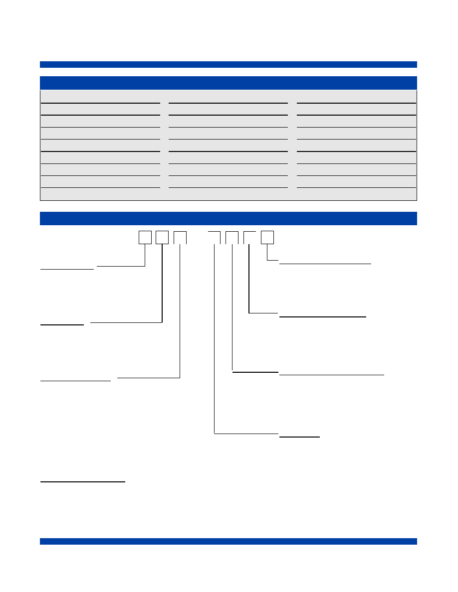
How to Order
FX-102 -
D
F
C
-
A
1
P
6
Supply Voltage
C = 5 Vdc ±5%
D = 3.3 Vdc ±5%
Output Type
F = Comp. PECL
Temperature Range
C = 0∞C to +70∞C
F = -40∞C to +85∞C
Output Frequency (2 to 7)
See Frequency Chart Above
*If not listed enter S in this block and then list the
output frequencies after the part number.
Input Frequency (C to 7)
See Frequency Chart Above
*If not listed or more than one frequency enter S in
this block and then list all the input frequencies
after the part number.
Number of Input Frequencies
1 = 1 Input Frequency
2 = *2 Input Frequencies
3 = *3 Input Frequencies
4 = *4 Input Frequencies
Input Logic
A = HCMOS
D = PECL
*If not listed or more than one input frequency a
special SCD number will be assigned at point of order.
Part Number Examples:
FX-102-DFC-D1P6
*FX-102-DFF-A4S6, S = 8 kHz, 1.544 MHz, 2.048 MHz, 19.44 MHz
*FX-102-DFC-D16S, S = 166.6286 MHz
8 kHz
C
16 kHz
D
64 kHz
E
1.024 MHz
F
1.544 MHz
H
2.048 MHz
J
4.096 MHz
K
8.192 MHz
L
13.00 MHz
M
16.384 MHz
N
19.44 MHz
P
20.48 MHz
R
26.00 MHz
T
27.00 MHz
W
38.88 MHz
X
44.736 MHz
Y
51.84 MHz
0
61.44 MHz
1
77.76 MHz
2
82.944 MHz
3
112 MHz
4
139.264 MHz
5
155.52 MHz
6
166.6286 MHz
7
Special SCD
S
Standard Frequencies
FX-102 Frequency Translator
Vectron International ∑
267 Lowell Road, Hudson, NH 03051 ∑ Tel:
1-88-VECTRON-1 ∑ REV 18Oct01
, 20Aug02
USA: Vectron International *
267 Lowell Road, Hudson, NH 03051........
Tel:1-88-VECTRON-1 * Fax:1-888-FAX-VECTRON
EUROPE: .................................................................................................Tel: 49 (0) 3328 4784 17 * Fax: 49 (0) 3328 4784 30
ASIA:...............................................................................Tel: +86 21 28909740 / 41 / 42 Fax: +86 21 28909240 / 28909999
www.vectron.com
Vectron International reser ves the right to make changes to the product(s) and/or information contained herein without notice.
No liability is assumed as a result of their use or application.
No rights under any patent accompany the sale of any such product(s) or information.
For additional information please contact:
Visit Our Website at
www.vectron.com