AMSC N/A
1 of 7
FSC 5955
DISTRIBUTION STATEMENT A. Approved for public release; distribution is unlimited.
INCH-POUND
MIL-PRF-55310/25B
8 July 2002
SUPERSEDING
MIL-PRF-55310/25A
25 March 1998
PERFORMANCE SPECIFICATION SHEET
OSCILLATOR, CRYSTAL CONTROLLED, TYPE 1 (CRYSTAL OSCILLATOR (XO)),
25 MHz THROUGH 175 MHz, HERMETIC SEAL, SQUARE WAVE, EMITTER COUPLED LOGIC
This specification is approved for use by all Departments
and Agencies of the Department of Defense.
The requirements for acquiring the product described herein
shall consist of this specification and MIL-PRF-55310.
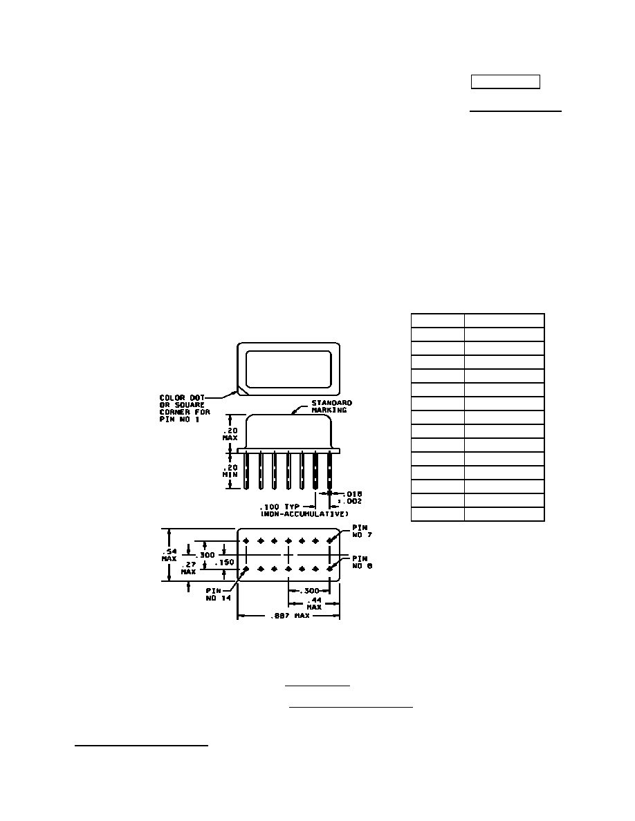
Configuration A
FIGURE 1. Dimensions and configuration.
Pin number
Function
1 NC
2 NC
3 NC
4 NC
5 NC
6 NC
7 B-
8 OUTPUT
9 NC
10 NC
11 NC
12 NC
13 NC
14 GND/CASE
Inches mm
.002
0.05
.018
0.46
.100
2.54
.150
3.81
.20
5.1
.27
6.9
.300
7.62
.44
11.2
.54
13.7
.887
22.53
MIL-PRF-55310/25B
2
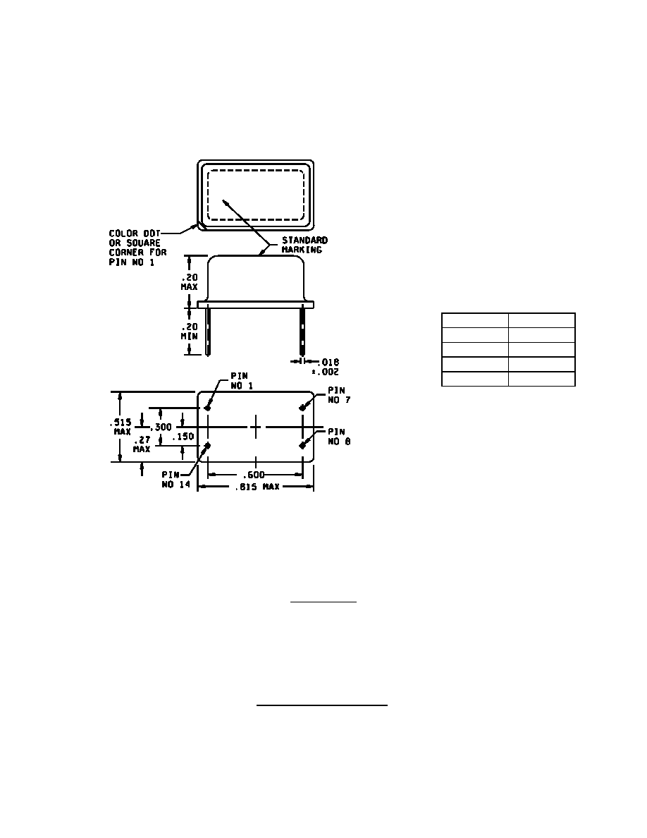
Configuration B
NOTES:
1. Dimensions are in inches.
2. Metric equivalents are given for general information only.
3. Unless otherwise specified, tolerances are ±.005 (0.13 mm) for three place decimals and ±.02 (0.5 mm) for two
place decimals.
4. All pins with the NC function may be connected internally and are not to be used as external tie points or
connections.
FIGURE 1. Dimensions and configurations - Continued.
Pin number
Function
1 NC
7 B-
8 Output
14 GND/case
Inches mm
.002
0.05
.018
0.46
.150
3.81
.20 5.1
.27 6.9
.300
7.62
.515
13.08
.600
15.24
.815
20.70

MIL-PRF-55310/25B
3
REQUIREMENTS:
Interface and physical dimensions: See figure 1.
Package configuration: See figure 1.
Terminals: See figure 1.
Weight: 0.5 ounces (14.175 grams), maximum.
* Oscillator: Class 2 (see 1.2.3 of MIL-PRF-55310).
Calibration: Manufacturer calibrated.
* Screening: In accordance with MIL-PRF-55310, product level B or S, as applicable.
Temperature:
Operating: See table I.
Storage: -62
∞
C to +125
∞
C.
Load test circuit: See figure 2.
Seal: Hermetic in accordance with MIL-PRF-55310, maximum leakage rate 5 x 10
-8
atm cc/s.
Supply voltage (B-): -5.2 V dc
±
5 percent.
Overvoltage survivability: In accordance with MIL-PRF-55310.
Supply current: At designated supply voltage (see table I).
Start-up time: 15 milliseconds maximum, measurement shall be taken at reference temperature and operating
temperature range endpoints.
Nominal output frequency: Frequency as designated at time of acquisition (see table I).
Output logic voltage levels: See figure 3.
Logic 1: -1.15 V dc minimum.
Logic 0: -1.54 V dc maximum.
Output waveform: Symmetrical square wave, emitter coupled logic compatible (see figure 3).
Duty cycle: See table I and figure 3.
Rise and fall times (see table I): Measurements shall be taken at the 20 percent and 80 percent peak-to-peak
output voltage levels, with peak-to-peak output defined as Logic 1 - Logic 0 (see figure 3).
Initial accuracy at reference temperature: See table I.
Initial frequency-temperature accuracy (1/2 temperature cycle): See table I. Measurements shall be taken at ten
equally spaced increments over the specified operating temperature range.
MIL-PRF-55310/25B
4
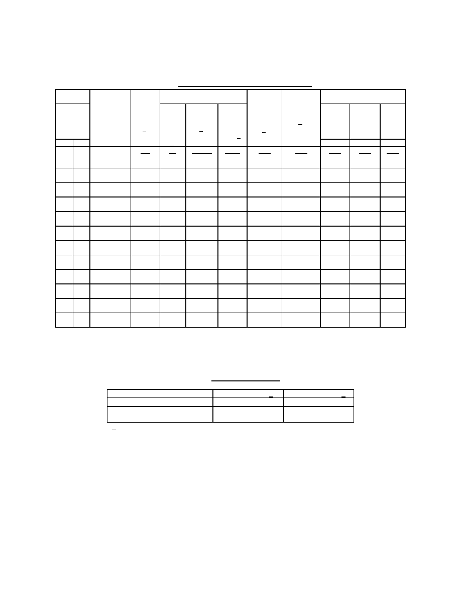
TABLE I. Dash numbers and operating characteristics.
1/ See figure 3.
2/ See figure 2.
3/ Up to 30 days following shipment.
4/ After 30 days following shipment.
TABLE II. Frequency aging limits.
1/ See table I.
Frequency-voltage tolerance
±
1 ppm maximum for a
±
5 percent change in supply voltage. Measurements shall be
taken at reference temperature and operating temperature range endpoints.
Frequency-environmental tolerance:
±
3 ppm.
Frequency aging: Frequency aging shall be in accordance with MIL-PRF-55310 and shall meet the limits of table II.
Vibration, sinusoidal: Method 204 of MIL-STD-202.
Nonoperating: Test condition D.
Operating: Not required.
Dash
number
Output
frequency
Input
current
Pulse characteristics
Initial
accuracy
Frequency
aging
Frequency-temperature
tolerance (ppm)
Config-
uration
range max
at
5.25 V
±
5%
2/
Rise
and
fall
times
max
Duty
cycle
min-max
1/
Load
(test)
to
-2.0
V dc 2/
at
+23
∞
C
±
1
∞
C
3/
per year
(max)
4/
-55
∞
C
to
+125
∞
C
-55
∞
C
to
+105
∞
C
-20
∞
C
to
+70
∞
C
A B
1/
A B C
mA ns percent ohms ppm ppm ppm ppm ppm
02
03
25 MHz to
100 MHz
50
3.5
40 to 60
50
±
15
±
5
±
65
±
55
±
40
06
07
25 MHz to
100 MHz
75
3.5
40 to 60
100
±
15
±
5
±
65
±
55
±
40
10
11
25 MHz to
100 MHz
50
3.5
40 to 60
50
±
25
±
10
±
100
±
75
±
50
14
15
25 MHz to
100 MHz
75
3.5
40 to 60
100
±
25
±
10
±
100
±
75
±
50
32
33
100 MHz to
125 MHz
60
3.5
40 to 60
50
±
15
±
5
±
65
±
55
±
40
36
37
100 MHz to
125 MHz
75
3.5
40 to 60
100
±
15
±
5
±
65
±
55
±
40
40
41
100 MHz to
125 MHz
60
3.5
40 to 60
50
±
25
±
10
±
100
±
75
±
50
44
45
100 MHz to
125 MHz
60
3.5
40 to 60
100
±
25
±
10
±
100
±
75
±
50
62
63
125 MHz to
175 MHz
70
3.0
40 to 60
50
±
15
±
5
±
65
±
55
±
40
66
67
125 MHz to
175 MHz
125
3.0
40 to 60
100
±
15
±
5
±
65
±
55
±
40
70
71
125 MHz to
175 MHz
70
3.0
40 to 60
50
±
25
±
10
±
100
±
75
±
50
74
75
125 MHz to
175 MHz
125
3.0
40 to 60
100
±
25
±
10
±
100
±
75
±
50
5 ppm per year 1/
10 ppm per year 1/
Maximum change over 30 days
±
0.7 ppm
±
1.5 ppm
Projected maximum change
for 1 year after 30 days
±
5.0 ppm
±
10.0 ppm
MIL-PRF-55310/25B
5
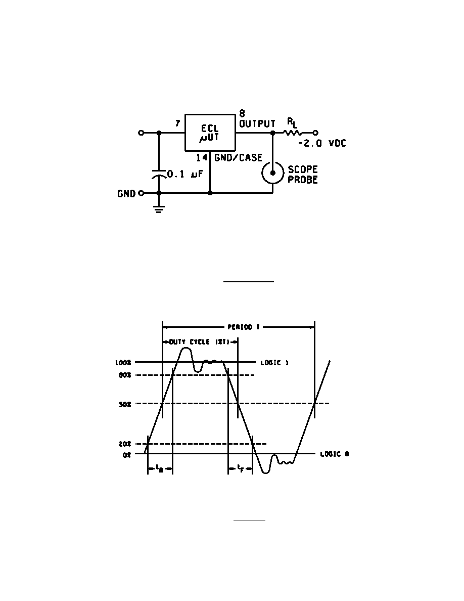
B-
*
NOTE: R
L
= 50
or 100
(see table I).
FIGURE 2. Load test circuit.
FIGURE 3. Waveform.