 | –≠–ª–µ–∫—Ç—Ä–æ–Ω–Ω—ã–π –∫–æ–º–ø–æ–Ω–µ–Ω—Ç: TFS101 | –°–∫–∞—á–∞—Ç—å:  PDF PDF  ZIP ZIP |

tfs101.doc
version 2.0 - 01/98
______________________________________________________________________________________________________
VI
TELEFILTER
SAW-Filter Specification
TFS 101 - 1/4
______________________________________________________________________________________________________
Measurement Condition
Ambient Temperature:
23
∞
C
Input Power Level:
10 dBm
Terminating Impedances 1.3k
// -2pF
Characteristics
Remark:
Reference level for the relative attenuation arel is the minimum of the pass band attenuation amin. The minimum of the pass
band attenuation amin is defined as the insertion loss ae. The nominal frequency f
N
is fixed on 101,255 MHz.
D a t a
typ. Value
Variation/ Limitation
______________________________________________________________________________________________________
Input Power Level
-
max.
10
dBm
______________________________________________________________________________________________________
Insertion Loss
ae = amin
-
max.
5
dB
(Reference Level)
______________________________________________________________________________________________________
Nominal Frequency
f
N
-
101,255 MHz
______________________________________________________________________________________________________
Amplitude Ripple in Pass Band
f
N
... f
N
± 10 kHz
-
max.
0,5 dB
______________________________________________________________________________________________________
Relative Attenuation
arel
f
N
± 10
kHz ... f
N
±
20
kHz
-
max.
2
dB
f
N
± 20
kHz ... f
N
±
25
kHz
-
max.
3
dB
f
N
± 55
kHz ... f
N
±
80
kHz
-
min.
5
dB
f
N
± 80
kHz ... f
N
± 100
kHz
-
min.
23
dB
f
N
± 100
kHz ... f
N
± 200
kHz
-
min.
28
dB
f
N
+ 200
kHz ... f
N
+ 400
kHz
-
min.
50
dB
f
N
- 200
kHz ... f
N
- 895
kHz
-
min.
50
dB
f
N
- 895
kHz ... f
N
- 925
kHz
-
min.
70
dB
______________________________________________________________________________________________________
Intermodulation
I.M.
Input Frequency
F1
-
+ 100 kHz, + 200 kHz
F2
-
- 100 kHz, - 200 kHz
Input Level
-
- 30
dBm
I.M. Products
-
max.- 110
dBm
______________________________________________________________________________________________________
Group Delay Distortion
GDD
f
N
... f
N
± 15 kHz
-
max.
5
µs
______________________________________________________________________________________________________
Operating Temperature Range
- 25 ∞C ... + 75 ∞C
Storage Temperature Range
- 40 ∞C ... + 85 ∞C
______________________________________________________________________________________________________
Temperature Coefficient
TC
- 0,036 ppm/K≤
-
______________________________________________________________________________________________________
Frequency Inversion Temperature
25
∞C
-
______________________________________________________________________________________________________
Generated:
Checked / Approved:
______________________________________________________________________________________________________
VI TELEFILTER / Potsdamer Straþe 18 / D 14 513 TELTOW
Phone: (+33 28) 47 84 52 / Fax: (+33 28) 47 84 30 / E-Mail: tft@telefilter.com
tfs101.doc
version 2.0 - 01/98
______________________________________________________________________________________________________
VI
TELEFILTER
SAW-Filter Specification
TFS 101 - 2/4
______________________________________________________________________________________________________
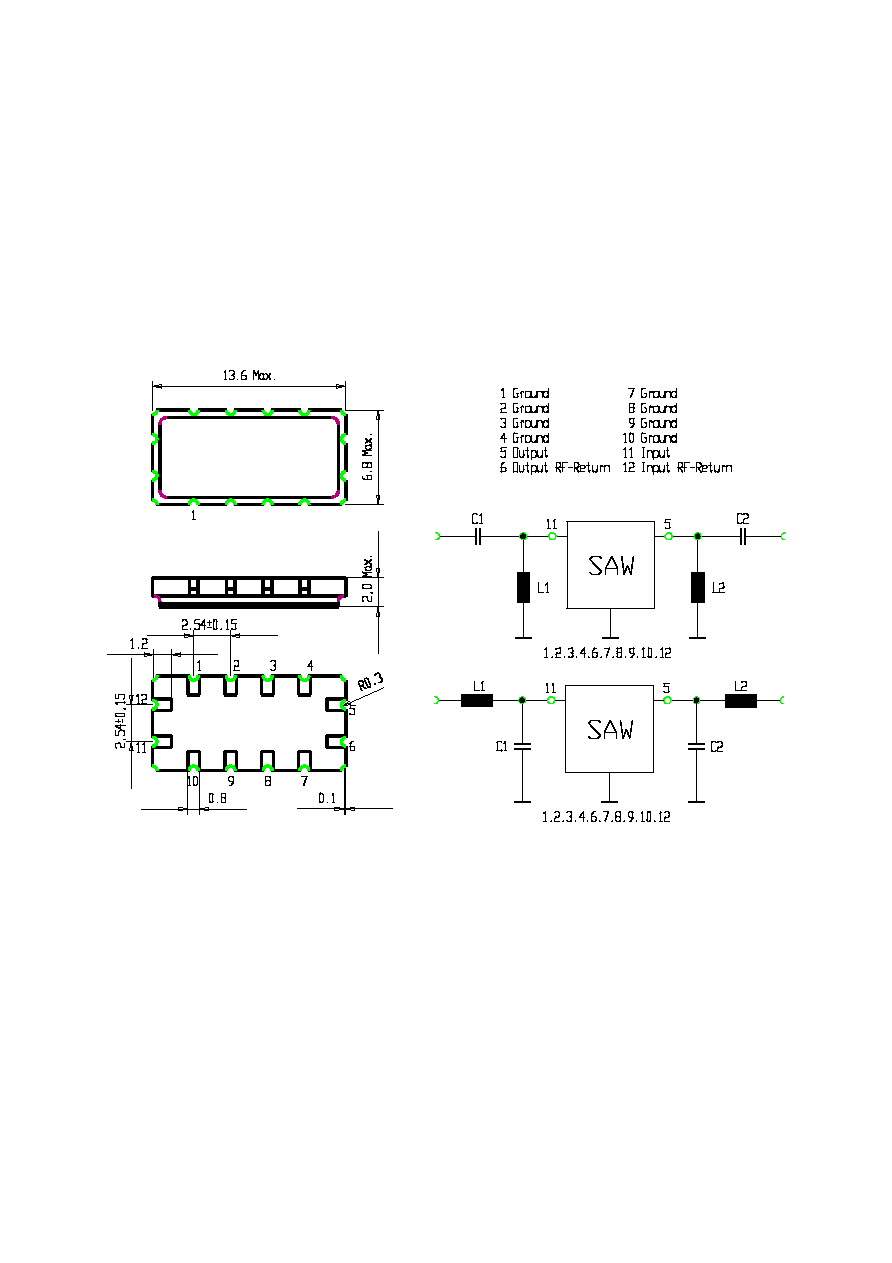
Construction, Pin Connection and 50
Matching Network
(All Dimensions in mm)
TFS 101
tft H9
______________________________________________________________________________________________________
VI TELEFILTER / Potsdamer Straþe 18 / D 14 513 TELTOW
Phone: (+33 28) 47 84 52 / Fax: (+33 28) 47 84 30 / E-Mail: tft@telefilter.com
tfs101.doc
version 2.0 - 01/98
______________________________________________________________________________________________________
VI
TELEFILTER
SAW-Filter Specification
TFS 101 - 3/4
______________________________________________________________________________________________________
Stability Characteristics
After the following tests the filter shall meet the whole specification:
1. Shock:
30g, 18 ms, half sine wave, 3 shocks each plane;
DIN IEC 68 T2 - 27
2. Vibration:
10 Hz to 500 Hz, 0,075 mm or 1g respectively, 1 octave per min, 10 cycles per plan, 3 plans;
DIN IEC 68 T2 - 6
3. Damp heat:
90 % to 95 % rel. humidity, 40 ∞C, 10 days;
(steady state)
DIN IEC 68 - 2 - 3
4. Resistance to
solder heat (reflow):
max. 2 times reflow process;
for temperature conditions refer to the attached "Air reflow temperature conditions" on sheet 4;
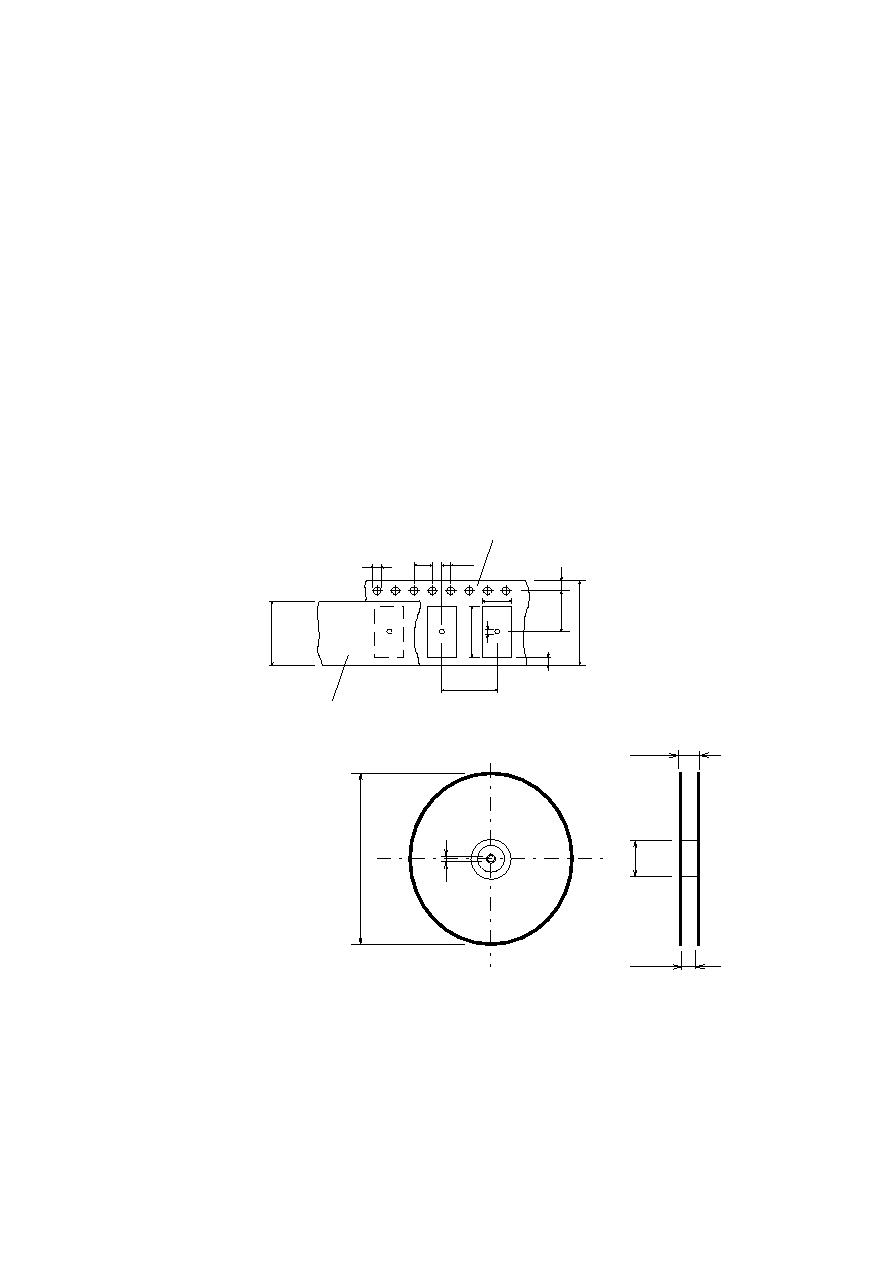
Packing
Tape & Reel:
DIN IEC 286 - 3, with exception of value for N and minimum bending radius;
tape type
II
,
embossed carrier tape with top cover tape on the upper side;
max. pieces of filters per reel: 1700
D o
P
o
E
F
W
P
1
EMBOSSED CARRIER TAPE
COVER TAPE
G
P
2
B
o
A
o
21,4
± 0,1
D
1
Tape (all dimensions in mm)
W : 24 ± 0,3
Po : 4 ± 0,1
Do : 1,5 + 0,5
E : 1,75 ± 0,1
F : 11,5 ± 0,1
G (min) : 0,75
P2 : 2 ± 0,1
P1 : 12 ± 0,1
D1(min) : 1,5
Ao : 7,1 ± 0,2
Bo : 13,9 ± 0,2
D1 : 1,5 + 0,5
A
C
N
W
1
W 2
Reel (all dimensions in mm):
A : 330
W1 : 24,4 +2
W2 (max) : 30,4
N (min) : >= 90
C : 13 ± 0,25
The minimum bending radius is 45 mm. The mounting surface of the filters faces the bottom side of the embossed carrier tape.
The marking of the filters is able to read if the view is directed on the upper side of the carrier tape with the sprocket holes on
the right side of the tape.
______________________________________________________________________________________________________
VI TELEFILTER / Potsdamer Straþe 18 / D 14 513 TELTOW
Phone: (+33 28) 47 84 52 / Fax: (+33 28) 47 84 30 / E-Mail: tft@telefilter.com
tfs101.doc
version 2.0 - 01/98
______________________________________________________________________________________________________
VI
TELEFILTER
SAW-Filter Specification
TFS 101 - 4/4
______________________________________________________________________________________________________
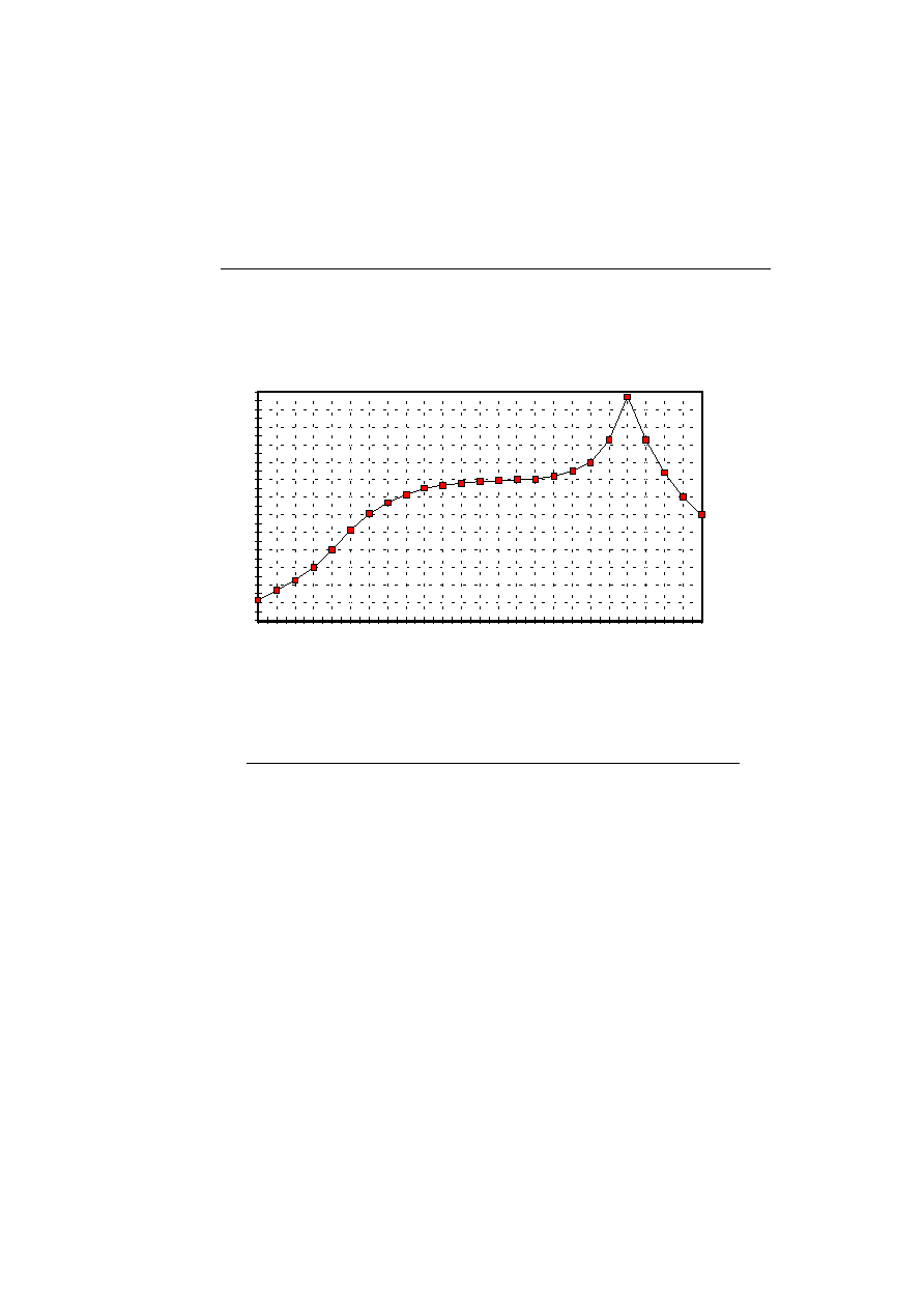
Air reflow temperature conditions
1st and 2nd air reflow profile
Name: pre-heating periods main-heating periods peak temperature
Temperature:
150 ∞C - 170 ∞C
over 200 ∞C
255 ∞C ± 5 ∞C
Time:
60 sec. - 90 sec.
20 sec. - 25 sec.
Chip-mount air reflow profile
time / sec.
temperature / ∞C
0
20
40
60
80
100
120
140
160
180
200
220
240
260
0
20
40
60
80
100
120
140
160
180
200
220
240
Table for temperature vs. time during the air reflow process
Tolerance of temperatures: ± 5 ∞C
time / sec. temperature / ∞C time / sec. temperature / ∞C
0
23
140
160
10
34
150
161
20
46
160
164
30
60
170
170
40
80
180
180
50
103
190
205
60
121
195
230
70
134
200
255
80
143
205
230
90
150
210
205
100
154
215
180
110
156
220
165
120
158
230
140
130
159
240
120
______________________________________________________________________________________________________
VI TELEFILTER / Potsdamer Straþe 18 / D 14 513 TELTOW
Phone: (+33 28) 47 84 52 / Fax: (+33 28) 47 84 30 / E-Mail: tft@telefilter.com