 | –≠–ª–µ–∫—Ç—Ä–æ–Ω–Ω—ã–π –∫–æ–º–ø–æ–Ω–µ–Ω—Ç: TFS1220 | –°–∫–∞—á–∞—Ç—å:  PDF PDF  ZIP ZIP |

TFS1220.doc version 1.4
21.08.02
VI TELEFILTER
Filter specification
TFS 1220 1/5
VI
TELEFILTER
Potsdamer Straþe 18
Measurement condition
Ambient temperature:
23
∞
C
Input power level:
0 dBm
Terminating impedances*:
input: 95
// -0.3 pF
output:
95
// -0.3 pF
Characteristics
Remark:
Reference level for the relative attenuation arel of the TFS 1220 is the minimum of the pass band attenuation amin. The minimum of the pass
band attenuation amin is defined as the insertion loss ae. The centre frequency fc is the arithmetic mean value of the upper and lower frequencies
at the 3 dB filter attenuation level relative to the insertion loss ae. The nominal frequency f
N
is fixed at 1220,0 MHz without tolerance. The given
values for the relative attenuation arel have to be reached at the frequencies given below even if the centre frequency f
c
is shifted due to the
temperature coefficient of frequency TCf in the operating temperature range and due to a production tolerance for the centre frequency f
c
D a t a
typ. value
Variation/ Limitation
Insertion loss
ae = amin
4,0 dB
max. 6,0 dB
(Reference level)
Nominal frequency
f
N
-
1220 MHz
Centre frequency
f
c
1220
MHz
Passband ripple
(P-P) within f
N
± 100 KHz
0,40 dB
max 1,0 dB
Group delay ripple within f
N
± 100 KHz
43,0
ns
max. 100
ns
Relative attenuation
arel
fN ....... fN ±
0,1 MHz
0,40 dB
max.
1
dB
fN ± 4 MHz ....... fN ±
5 MHz
25,0
dB
min.
10 dB
fN ± 5 MHz ....... fN ±
6 MHz
28,0
dB
min.
12 dB
fN ± 6 MHz ....... fN ± 20 MHz
37,0
dB
min.
14 dB
fN + 20 MHz ....... fN + 180 MHz
35,0
dB
min.
30 dB
fN - 20 MHz ....... fN - 1150 MHz
45,0
dB
min.
30 dB
Temperature coefficient of frequency
TC
f
-0,050
ppm/K≤
Frequency inversion temperature
40 ∞C
.
Operating temperature range
- 40 ∞C ... + 85 ∞C
Storage temperature range
- 45 ∞C ... + 90 ∞C
Input power level
max.
10
dBm
*)
The terminating impedances depend on parasitics and q-values of matching elements and the board used, and are to be understood as
reference values only. Should there be additional questions do not hesitate to ask for an application note or contact our design team.
generated :
checked / approved :
D 14 513 TELTOW / Germany
Tel: (+49) 3328 4784-0 / Fax: (+49) 3328 4784-30
Mail:
tft@telefilter.com
VI TELEFILTER reserves the right to make changes to the product(s) and/or information contained herein without notice. No liability is
assumed as a result of their use or application. No rights under any patent accompany the sale of any such product(s) or information.
TFS1220.doc version 1.4
21.08.02
VI TELEFILTER
Filter specification
TFS 1220 2/5
VI
TELEFILTER
Potsdamer
Straþe
18
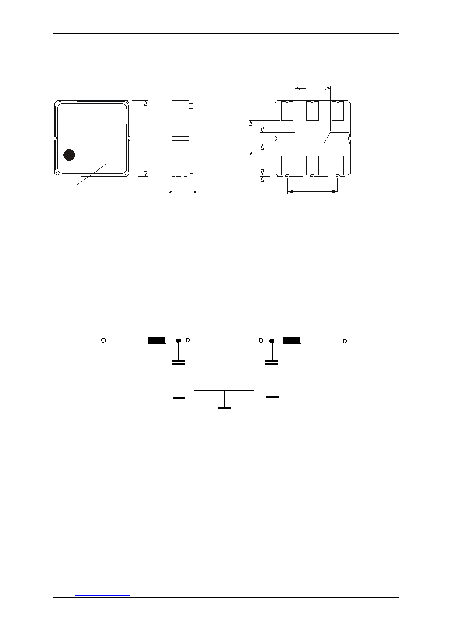
Construction, pin configuration and 50
- matching network
(All dimensions in mm)
1,78
SQ 3,81
+ 0,2 / -0,1
5
7
3
D
1
ate code
P34
1220
1,78
0,1
0,6
2,54
1,2 Max.
date code:
year + week
M 2000
N 2001
P 2002
...
Pin 1 Input
Pin 5 Output
Pin 2 Ground
Pin 6 Ground
Pin 3 Ground
Pin 7 Ground
Pin 4 Package Ground
Pin 8 Package ground
50 Ohm Test circuit
L1
5
1
SAW
C1
L1
C2
L2
Input,
50 Ohm
2,3,4,6,7,8
Output,
50 Ohm
D 14 513 TELTOW / Germany
Tel: (+49) 3328 4784-0 / Fax: (+49) 3328 4784-30
E-Mail:
tft@telefilter.com
VI TELEFILTER reserves the right to make changes to the product(s) and/or information contained herein without notice. No liability is
assumed as a result of their use or application. No rights under any patent accompany the sale of any such product(s) or information
TFS1220.doc version 1.4
21.08.02
VI TELEFILTER
Filter specification
TFS 1220 3/5
VI
TELEFILTER
Potsdamer
Straþe
18
Stability Characteristics
After the following tests the filter shall meet the whole specification:
1. Shock:
500g, 18 ms, half sine wave, 3 shocks each plane;
DIN IEC 68 T2 - 27
2. Vibration:
10 Hz to 500 Hz, 0,35 mm or 5g respectively, 1 octave per min, 10 cycles per plan, 3 plans;
DIN IEC 68 T2 - 6
3. Change of
-55 ∞C to 125∞C / 30 min. each / 10 cycles
temperature:
DIN IEC 68 part 2 ≠ 14 Test N
4. Resistance to
solder heat (reflow):
reflow possible: twice max.;
for temperature conditions, please refer to the attached "Air reflow temperature conditions" on page
4;
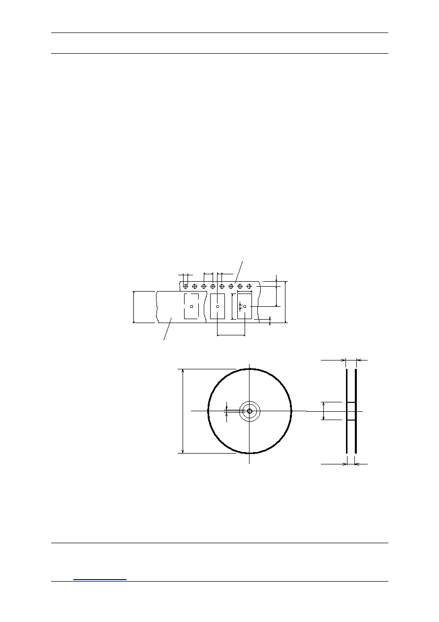
Packing
Tape & Reel:
IEC 286 - 3, with exception of value for N and minimum bending radius;
tape
type
II, embossed carrier tape with top cover tape on the upper side;
max. pieces of filters per reel:
3000
reel of empty components at start:
min 300 mm
reel of empty components at start including leader:
min 500 mm
trailer
min 300 mm
Do
P
o
E
F
W
P
1
EMBOSSED CARRIER TAPE
COVER TAPE
G
P
2
B
o
A
o
CT
D
1
Tape (all dimensions in mm)
W : 12 ± 0,3
Po : 4 ± 0,1
Do : 1,5 + 0,1
E : 1,75 ± 0,1
F : 5,5 ± 0,05
G (min) : 0,75
P2 : 2 ± 0,05
P1 : 8 ± 0,1
D1(min) : 1,5
Ao : 4,3 ± 0,1
Bo : 4,3 ± 0,1
CT : 9,5 ± 0,1
A
C
N
W
1
W
2
Reel (all dimensions in mm):
A : 330
W1 : 12,4 + 2,0
W2 (max) : 18,4
N (min) : 50
C : 13 -+0,5/ -0,2
The minimum bending radius is 45 mm. The mounting surface of the filters faces the bottom side of the embossed carrier tape.
Markings on the filters can be read if the upper side of the carrier tape is regarded with the sprocket holes on its right.
D 14 513 TELTOW / Germany
Tel: (+49) 3328 4784-0 / Fax: (+49) 3328 4784-30
E-Mail:
tft@telefilter.com
VI TELEFILTER reserves the right to make changes to the product(s) and/or information contained herein without notice. No liability is
assumed as a result of their use or application. No rights under any patent accompany the sale of any such product(s) or information
TFS1220.doc version 1.4
21.08.02
VI TELEFILTER
Filter specification
TFS 1220 4/5
VI
TELEFILTER
Potsdamer
Straþe
18
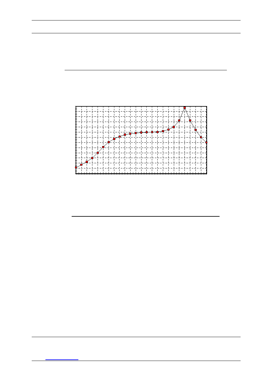
Air reflow temperature conditions
1st and 2nd air reflow profile
Name:
pre-heating
periods
main-heating periods
peak temperature
Temperature:
150 ∞C - 170 ∞C
over 200 ∞C
255 ∞C ± 5 ∞C
Time:
60 sec. - 90 sec.
20 sec. - 25 sec.
Chip-mount air reflow profile
time / sec.
t
e
mper
at
ur
e /
∞C
0
20
40
60
80
100
120
140
160
180
200
220
240
260
0
20
40
60
80
100
120
140
160
180
200
220
240
Table for temperature vs. time during the air reflow process
Tolerance of temperatures: ± 5 ∞C
time / sec.
temperature / ∞C
time / sec.
temperature / ∞C
0
23
140
160
10
34
150
161
20
46
160
164
30
60
170
170
40
80
180
180
50
103
190
205
60
121
195
230
70
134
200
255
80
143
205
230
90
150
210
205
100
154
215
180
110
156
220
165
120
158
230
140
130
159
240
120
D 14 513 TELTOW / Germany
Tel: (+49) 3328 4784-0 / Fax: (+49) 3328 4784-30
E-Mail:
tft@telefilter.com
VI TELEFILTER reserves the right to make changes to the product(s) and/or information contained herein without notice. No liability is
assumed as a result of their use or application. No rights under any patent accompany the sale of any such product(s) or information

TFS1220.doc version 1.4
21.08.02
VI TELEFILTER
Filter specification
TFS 1220 5/5
VI
TELEFILTER
Potsdamer
Straþe
18
History
Version
Reason of Changes
Name
Date
1.0
- Generation of development specification according to customer specification
Dr. Sabah
26.03.2002
1.1
- changing range of storage temperature
Pfeiffer
05.04.2002
- reducing maximum of insertion loss to 4 dB
- changing relativ attenuation
1.2
- change insertion loss and relative attenuation
Dr. Sabah
18.07.2002
1.3
- Preliminary Specification; add of typical values and terminating impedance
Dr. Sabah
19.08.2002
1.4
- Filter Specification; add of terminating impedance and frequency
Dr. Sabah
21.08.2002
inversion temperature
D 14 513 TELTOW / Germany
Tel: (+49) 3328 4784-0 / Fax: (+49) 3328 4784-30
E-Mail:
tft@telefilter.com
VI TELEFILTER reserves the right to make changes to the product(s) and/or information contained herein without notice. No liability is
assumed as a result of their use or application. No rights under any patent accompany the sale of any such product(s) or information