 | –≠–ª–µ–∫—Ç—Ä–æ–Ω–Ω—ã–π –∫–æ–º–ø–æ–Ω–µ–Ω—Ç: TFS246K1 | –°–∫–∞—á–∞—Ç—å:  PDF PDF  ZIP ZIP |

tfs246kc.doc
version
1.1
01/99
______________________________________________________________________________________________________
VI TELEFILTER
Filter specification TFS 246 K1 1/4
______________________________________________________________________________________________________
______________________________________________________________________________________________________
VI TELEFILTER
Vectron International, Inc.
Potsdamer Straþe 18
267 Lowell Road
D 14 513 TELTOW / Germany
Hudson, NH 03051 / USA
Tel: (+49) 3328 4784-52 / Fax: (+49) 3328 4784-30
Tel: (603) 598-0070 Fax: (603) 598-0075
E-Mail: tft@telefilter.com
E-Mail: vti@vtinh.com
VI TELEFILTER reserves the right to make changes to the product(s) and/or information contained herein without notice. No liability is
assumed as a result of their use or application. No rights under any patent accompany the sale of any such product(s) or information.
Measurement condition
Ambient temperature:
23
∞
C
Input power level:
0 dBm
Terminating impedance: 450
||
-3.4 pF
Construction and pin connection
see page 2
Characteristics
Remark:
Reference level for the relative attenuation arel of the TFS 246 K1 is the minimum of the pass band attenuation amin. The minimum of the pass
band attenuation amin is defined as the insertion loss ae. The centre frequency fo is the arithmetic mean value of the upper and lower frequencies at
the 3 dB filter attenuation level relative to the insertion loss ae. The nominal frequency fN is fixed on 246 MHz without tolerance. The given values
for the relative attenuation arel and for the group delay ripple have to be reached at the frequencies given below also if the centre frequency fo is
shifted due to the temperature coefficient of frequency TCf in the operating temperature range and due to a production tolerance for the centre
frequency fo.
P r e l i m i n a r y D a t a
typ. value
limit
______________________________________________________________________________________________________
Insertion loss
ae = amin
6
dB
max 7
dB
(Reference level)
______________________________________________________________________________________________________
Center frequency
fo
246
MHz
-
Norminal frequency
fN
-
246
MHz
______________________________________________________________________________________________________
Relative attenuation
arel
246,0 MHz ± 80
kHz
max 3
dB
246,0 MHz ± 200
kHz ... 246,0 MHz ± 400
kHz
12
min 10
dB
246,0 MHz ± 400
kHz ... 246,0 MHz ± 600
kHz
30
min 25
dB
246,0 MHz ± 600
kHz ... 246,0 MHz ± 1,6 kHz
35
min 31
dB
246,0 MHz ±
1,6 MHz ... 246,0 MHz ±
3
MHz
50
min 41
dB
246,0 MHz ±
3
MHz ... 246,0 MHz ± 25
MHz
55
min 50
dB
______________________________________________________________________________________________________
Group delay distortion
GDD
246,0 MHz ± 50
kHz
0,7
µ
s
max 1,2
µ
s
246,0 MHz ± 75
kHz
1,1
µ
s
max 2,5
µ
s
______________________________________________________________________________________________________
Operating temperature range
- 20
∞
C ... + 85
∞
C
______________________________________________________________________________________________________
Temperature coefficient of frequency
TC
ca. - 0,036 ppm/K≤
______________________________________________________________________________________________________
Frequency inversion temperature
+ 20 ... + 30
∞
C
______________________________________________________________________________________________________
Generated:
Checked / approved:
tfs246kc.doc
version
1.1
01/99
______________________________________________________________________________________________________
VI TELEFILTER
Filter specification TFS 246 K1 2/4
______________________________________________________________________________________________________
______________________________________________________________________________________________________
VI TELEFILTER
Vectron International, Inc.
Potsdamer Straþe 18
267 Lowell Road
D 14 513 TELTOW / Germany
Hudson, NH 03051 / USA
Tel: (+49) 3328 4784-52 / Fax: (+49) 3328 4784-30
Tel: (603) 598-0070 Fax: (603) 598-0075
E-Mail: tft@telefilter.com
E-Mail: vti@vtinh.com
VI TELEFILTER reserves the right to make changes to the product(s) and/or information contained herein without notice. No liability is
assumed as a result of their use or application. No rights under any patent accompany the sale of any such product(s) or information.
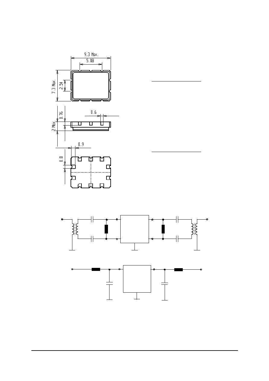
Construction, pin connection and 50
matching network
TFS246K1
tft L1
1
2
3
4
6
5
7
8
9
10
3 Ground
4 Ground
1 Output
8 Ground
7 Input
9 Ground
5 Ground
10 Ground
6 Input
2 Output
Pinning - balanced
3 Ground
4 Ground
1 Output
8 Ground
7 RF-Return
9 Ground
5 Ground
10 Ground
6 Input
2 RF Return
Pinning - unbalanced
50
test circuit (balanced)
2
1
6
7
3,4,5,8,9,10
LB-IN
LB-OUT
SAW
C1
C2
C3
C4
L1
L2
50
test circuit (unbalanced)
1
6
2,3,4,5,7,8,9,10
SAW
C5
C6
L3
L4
tfs246kc.doc
version
1.1
01/99
______________________________________________________________________________________________________
VI TELEFILTER
Filter specification TFS 246 K1 3/4
______________________________________________________________________________________________________
______________________________________________________________________________________________________
VI TELEFILTER
Vectron International, Inc.
Potsdamer Straþe 18
267 Lowell Road
D 14 513 TELTOW / Germany
Hudson, NH 03051 / USA
Tel: (+49) 3328 4784-52 / Fax: (+49) 3328 4784-30
Tel: (603) 598-0070 Fax: (603) 598-0075
E-Mail: tft@telefilter.com
E-Mail: vti@vtinh.com
VI TELEFILTER reserves the right to make changes to the product(s) and/or information contained herein without notice. No liability is
assumed as a result of their use or application. No rights under any patent accompany the sale of any such product(s) or information.
Stability characteristics
After the following tests the filter shall meet the whole specification:
1. Shock:
30g, 18 ms, half sine wave, 3 shocks each plane;
DIN IEC 68 T2 - 27
2. Vibration:
10 Hz to 150 Hz, 0.35 mm amplitude, 5g; 2 hours for 3 planes;
DIN IEC 68 T2 - 6
3. Damp heat:
90 % to 95 % rel. humidity, 40 ∞C, 10 days;
IEC Pub. 68 - 2 - 3
4. Resistance to
solder heat (Reflow):
260 ∞C for 10 sec;
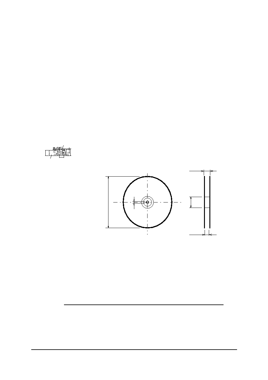
Packing
Tape & Reel:
DIN IEC 286 - 3, with exception of value for N and minimum bending radius;
tape type
II
,
embossed carrier tape with top cover tape on the upper side;
pcs per reel: 2000
Do
Po
E
F
W
P1
EMBOSSED CARRIER TAPE
COVER TAPE
G
P 2
Bo
A o
13,4
± 0,1
D1
Tape (all dimensions in mm)
W : 16 ± 0,3
Po : 4 ± 0,1
Do : 1,5 + 0,5
E : 1,75 ± 0,1
F : 7,5 ± 0,1
G (min) : 0,75
P2 : 2 ± 0,1
P1 : 12 ± 0,1
D1(min) : 1,5
Ao : 7,6 ± 0,1
D1 : 1,5 + 0,5
A
C
N
W
1
W 2
Reel (all dimensions in mm):
A : 330
W1 : 16,4 +2
W2 (max) : 22,4
N (min) : >= 90
C : 13 ± 0,25
The minimum bending radius is 45 mm. The mounting surface of the filters faces the bottom side of the embossed carrier tape.
The marking of the filters is able to read if the view is directed on the upper side of the carrier tape with the sprocket holes on
the right side of the tape.
Air reflow temperature conditions
1st and 2nd air reflow profile
Name: pre-heating periods main-heating periods peak temperature
Temperature:
150 ∞C - 170 ∞C
over 200 ∞C
255 ∞C ± 5 ∞C
Time:
60 sec. - 90 sec.
20 sec. - 25 sec.
tfs246kc.doc
version
1.1
01/99
______________________________________________________________________________________________________
VI TELEFILTER
Filter specification TFS 246 K1 4/4
______________________________________________________________________________________________________
______________________________________________________________________________________________________
VI TELEFILTER
Vectron International, Inc.
Potsdamer Straþe 18
267 Lowell Road
D 14 513 TELTOW / Germany
Hudson, NH 03051 / USA
Tel: (+49) 3328 4784-52 / Fax: (+49) 3328 4784-30
Tel: (603) 598-0070 Fax: (603) 598-0075
E-Mail: tft@telefilter.com
E-Mail: vti@vtinh.com
VI TELEFILTER reserves the right to make changes to the product(s) and/or information contained herein without notice. No liability is
assumed as a result of their use or application. No rights under any patent accompany the sale of any such product(s) or information.
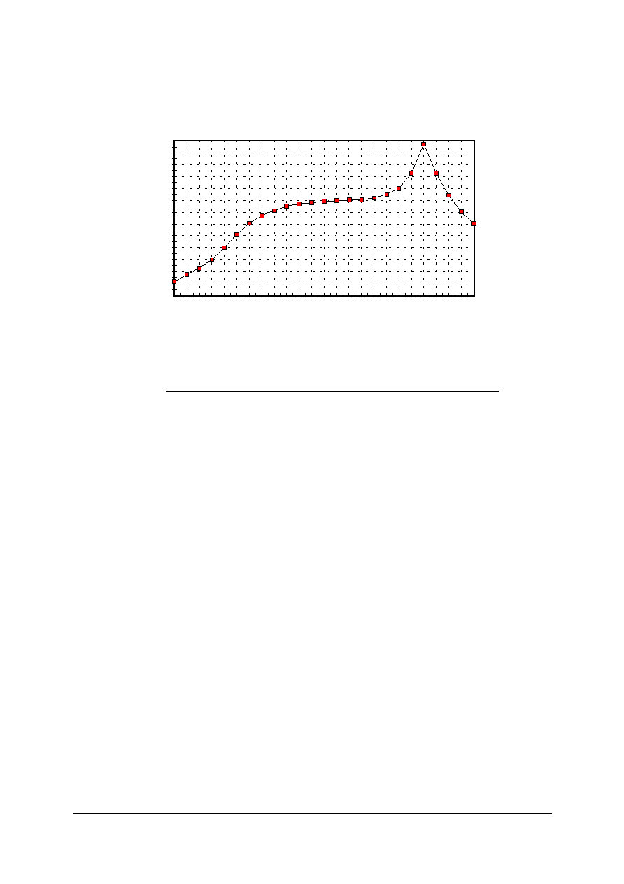
Chip-mount air reflow profile
time / sec.
temperature / ∞C
0
20
40
60
80
100
120
140
160
180
200
220
240
260
0
20
40
60
80
100
120
140
160
180
200
220
240
Table for temperature vs. time during the air reflow process
Tolerance of temperatures: ± 5 ∞C
time / sec. temperature / ∞C time / sec. temperature / ∞C
0
23
140
160
10
34
150
161
20
46
160
164
30
60
170
170
40
80
180
180
50
103
190
205
60
121
195
230
70
134
200
255
80
143
205
230
90
150
210
205
100
154
215
180
110
156
220
165
120
158
230
140
130
159
240
120