 | –≠–ª–µ–∫—Ç—Ä–æ–Ω–Ω—ã–π –∫–æ–º–ø–æ–Ω–µ–Ω—Ç: TFS71D | –°–∫–∞—á–∞—Ç—å:  PDF PDF  ZIP ZIP |

TFS71D
09/97
__________________________________________________________________________________
VI
TELEFILTER
Specification TFS 71 D - Page 1/3
__________________________________________________________________________________
1. Measurement Condition
Ambient temperature TA:
23 ∞C
Input power level:
0 dBm
Source impedance:
50
(refer to page 2)
Load impedance:
50
(refer to page 2)
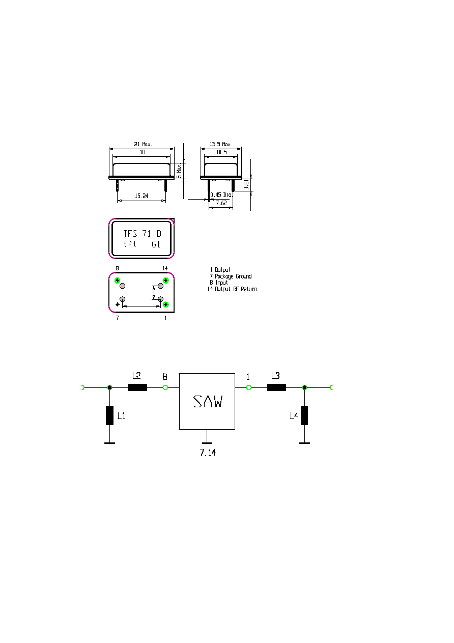
2. Construction and Pin Configuration
see page 2
3. Characteristics
Remark:
Reference level for the relative attenuation arel and the band width BW of the TFS 71 D is the minimum of the pass band
attenuation amin. The minimum of the pass band attenuation amin is defined as the insertion loss ae. The center frequency fo
is the arithmetic mean value of the upper and lower frequencies at the 1,5 dB filter attenuation level relative to the insertion loss
ae.
Description
typ. value
Variation / Limitation
______________________________________________________________________________________________________
Insertion Loss
ae
5,4 dB
max 8
dB
(Reference Level)
______________________________________________________________________________________________________
Center Frequency
fo
-
71,0
MHz
______________________________________________________________________________________________________
1 dB - Band Width
195
kHz
min
±
65
kHz
1,5 dB - Band Width
235
kHz
min
±
82,5
kHz
______________________________________________________________________________________________________
Relative Attenuation
arel
fo ± 200
kHz ... fo ± 400
kHz
-
min 4
dB
fo
±
400
kHz ... fo
±
600
kHz
-
min 20
dB
fo
±
600
kHz ... fo
±
800
kHz
-
min 25
dB
fo ± 800
kHz ... fo ±
1,6 MHz
-
min 27
dB
fo ±
1,6 MHz ... fo ± 10
MHz
-
min 35
dB
______________________________________________________________________________________________________
Group Delay
GD
2,15
µ
s
-
Group Delay Ripple
fo
±
80 kHz
200
ns
max 400
ns
______________________________________________________________________________________________________
Terminating Impedances
Input
832
// -15,1 pF
Output
1055
// -11,6 pF
______________________________________________________________________________________________________
Temperature Coefficient
TC 1st order
0
ppm/K
-
______________________________________________________________________________________________________
Operating Temperature Range
- 25 ∞C ... + 85 ∞C
______________________________________________________________________________________________________
DC - Voltage
Vdc *)
-
max 12
V
AC - Voltage
Vac *)
-
max 10
V
______________________________________________________________________________________________________
*)
Between any pins
__________________________________________________________________________________
VI
TELEFILTER / Potsdamer Straþe 18 / D - 14 513 TELTOW
Tel: +49 3328 4784-52 / Fax: +49 3328 4784-30 / E-Mail: tft@tft.telco-tech.de
TFS71D
09/97
__________________________________________________________________________________
VI
TELEFILTER
Specification TFS 71 D - Page 2/3
__________________________________________________________________________________
2. Construction and Pin Configuration
(All Dimensions in mm)
12,2
4,6
4. 50
Matching Network
5. Delivery Package Form
Only available without tape and reel. Filters stick on plastics plates and packed in folding carton ( each carton max. 150 pieces ).
__________________________________________________________________________________
VI
TELEFILTER / Potsdamer Straþe 18 / D - 14 513 TELTOW
Tel: +49 3328 4784-52 / Fax: +49 3328 4784-30 / E-Mail: tft@tft.telco-tech.de
TFS71D
09/97

__________________________________________________________________________________
VI
TELEFILTER
Specification TFS 71 D - Page 3/3
__________________________________________________________________________________
6. Environmental Test Conditions
Dry heat:
According to IEC 68 - 2 - 2; + 85 ∞C; 1000 hours.
Damp heat , steady state:
According to IEC 68 - 2 - 3; 92 % rel. humidity; + 40 ∞C, 21 days.
Damp heat , cyclic :
According to IEC 68 - 2 - 30; 95 % rel. humidity; + 20 ∞C / + 55 ∞C within
12 + 12-hour cycle; 6 days.
Vibration (sinusoidal):
According to IEC 68 - 2 - 6; 10 Hz - 500 Hz, 0,075 mm or 1g respectively,
1 octave per min, 10 cycles per plan, 3 plans;
Change of temperature:
According to IEC 68 - 2 - 14 and IEC 68 - 2 - 33; -25 ∞C / +85 ∞C, 10 cycles.
Resistance to solder heat:
According to IEC 68 - 2 - 20, test Tb, test method 1A; 260 ∞C; 10 sec.;
Solderability:
According to IEC 68 - 2 - 20; test Ta, test method 1;
soft solder L - Sn60 Pb40;
235 ∞C / 2 sec.; Flux is Kolophonium 25 % and Propanol 75 % or Ethanol 75 %;
Preconditioning is aging according to IEC 68 - 2 - 30;
95 % rel. humidity; +25 ∞C / +55 ∞C within 12 + 12-hour cycle; 6 days.
Absolute maximum ratings
Operating temperature range:- 25 ∞C / + 85 ∞C
Storage temperature range: - 40 ∞C / + 85 ∞C
Input power level :
0 dBm
Permissible humidity :
75 % in annual average;
Highest value:
95 % rel. humidity only 30 days within a year, otherwise 85 %; short term
formation of condensation is permissible.
Requirements after Tests
The limiting values of supplier have to be fulfilled. Neither mechanical nor electrical damages should happen.
__________________________________________________________________________________
VI
TELEFILTER / Potsdamer Straþe 18 / D - 14 513 TELTOW
Tel: +49 3328 4784-52 / Fax: +49 3328 4784-30 / E-Mail: tft@tft.telco-tech.de