VC-700
Voltage Controlled Crystal Oscillator
Features
∑ Small Industry Standard Package, 5.0 x 7.5 x 2.8 mm
∑ Output Frequencies from 77.76 MHz to 180 MHz
∑ 3.3 V or 5 V Operation
∑ HFF crystal for ultra low jitter
∑ Complementary PECL Outputs
∑ Low phase noise and custom options
∑ 0/70 ∫C or ≠40/85 ∫C operating temperature
∑ Enable /Disable (PECL)
Applications
PLL circuits for Clock Smoothing and Frequency Translation
∑ Fiber Channel
∑ SONET
∑ SDH, ITU-T G.709
∑ SONET, GR-253-CORE Issue3
Description
The VC-700 is a voltage controlled crystal oscillator that
operates at the fundamental frequency of the internal HFF
crystal. The HFF crystal is a high-Q quartz device that
enables the circuit to achieve low phase jitter performance
over a wide operating temperature range. The oscillator is
housed in an industry standard hermetically sealed leadless
surface mount package and is available on tape and reel.
10188_VECTRON 05/21/03 3:14 PM Page 1
VC-700 Voltage Controlled Crystal Oscillator
Vectron International ∑ 267 Lowell Road, Hudson, NH 03051 ∑ Tel: 1-88-VECTRON-1 ∑ Web: www.vectron.com
2
Electrical Performance
Parameter
Symbol
Minimum
Typical
Maximum
Units
Notes
Frequency
f
O
77.76
180
MHz
Supply Voltage
(+3.3V)
V
DD
3.15
3.3
3.45
V
(+5.0V)
V
DD
4.75
5.0
5.25
V
Supply Current
I
DD
<65
mA
Output Logic Levels
Output Logic High
0/70 ∞C
V
OH
Vcc -1.025
Vcc -0.880
V
Output Logic low
0/70 ∞C
V
OL
Vcc -1.810
Vcc -1.620
V
Output Logic High
-40/85 ∞C
V
OH
Vcc -1.085
Vcc -1.880
V
Output Logic low
-40/85 ∞C
V
OL
Vcc -1.830
Vcc -1.555
V
Transition Times
Rise Time
t
R
1
ns
Fall Time
t
F
1
ns
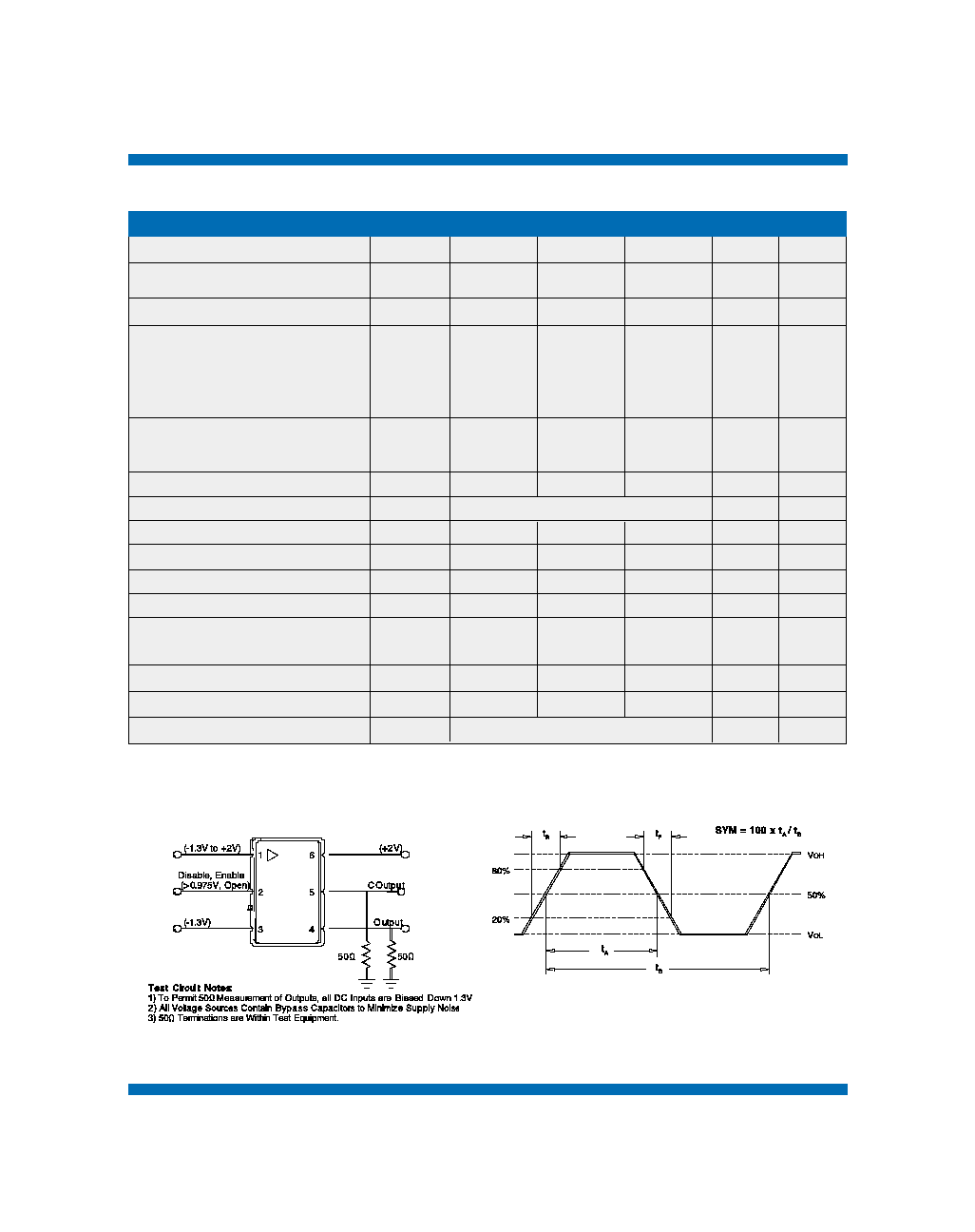
Symmetry or Duty Cycle
SYM
45
50
55
%
Operating Temperature
ordering option
0/70 or -40/85
∞C
Jitter (12 kHz ≠ 20 MHz BW)
0.3
ps (RMS)
Jitter (50 kHz ≠ 80 MHz BW)
0.5
ps (RMS)
Test Conditions for APR (+5V
option
)
V
C
0.5
4.5
V
Test Conditions for APR (+3.3V
option
)
V
C
0.3
3.0
V
Absolute Pull Range (APR)
APR
±32
ppm
±50
Gain Transfer
Positive
Control Voltage Bandwidth (-3dB)
BW
10
kHz
Package Size
5.0 x 7.5 x 2.8
10188_VECTRON 05/21/03 3:14 PM Page 2
VC-700 Voltage Controlled Crystal Oscillator
Vectron International ∑ 267 Lowell Road, Hudson, NH 03051 ∑ Tel: 1-88-VECTRON-1 ∑ Web: www.vectron.com
3
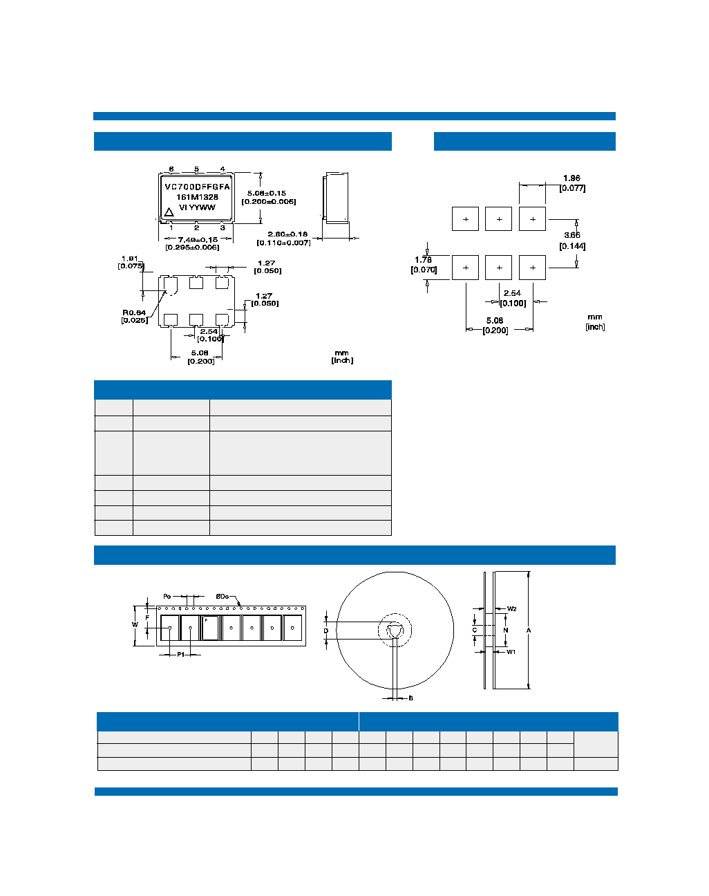
Pin Out
Tape and Reel (EIA-481-2-A)
Pin
Symbol
Function
1
2
3
4
5
6
Vc
N/C or OE
GND
Output
COutput
Vcc
VCXO Control Voltage
Output Disable
Enabled = PECL Logic 0 (or Open)
Disabled = PECL Logic 1
Case and Electrical Ground
Output
Complementary Output
Power Supply Voltage (3.3V or 5V)
Dimension
Tolerance
VC-700
W
Typ
16
F
Typ
7.5
Do
Typ
1.5
Po
Typ
4
P1
Typ
8
A
Typ
178
B
Min
1.5
C
Typ
13
D
Min
20.2
N
Min
50
W1
Typ
16.4
W2
Max
22.4
# Per
Reel
200
Outline Diagram
Pad Layout
Reel Dimension (mm)
Tape Dimensions (mm)
10188_VECTRON 05/21/03 3:14 PM Page 3
VC-700 Voltage Controlled Crystal Oscillator
4
Vectron International ∑ 267 Lowell Road, Hudson, NH 03051 ∑ Tel: 1-88-VECTRON-1 ∑ Web: www.vectron.com
Absolute Maximum Ratings
Parameter
Symbol
Ratings
Unit
Power Supply
Output Current
Voltage Control Range
Storage Temperature
Soldering Temp/Time
Vcc
lout
V
C
TS
T
LS
0 to 6
25
0 to Vcc
-55 to 125
220/10
V
mA
V
∞C
∞C/sec
Stresses in excess of the absolute maximum ratings can permanently damage the device. Functional operation is
not implied at these or any other conditions in excess of conditions represented in the operational sections of this
data sheet. Exposure to absolute maximum ratings for extended periods may adversely affect device reliability.
The VC-700 family is capable of meeting the following qualification tests:
Reliability
Although ESD protection circuitry has been designed into the VC-700 proper precautions should be taken when
handling and mounting. VI employs a human body model and a charged-device model (CDM) for ESD
susceptibility testing and design protection evaluation.
Handling Precautions
Parameter
Mechanical Shock
Mechanical Vibration
Solderability
Gross and Fine Leak
Resistance to Solvents
Human Body Model
Charged Device Model
500
500
Conditions
MIL-STD-883, Method 2002
MIL-STD-883, Method 2007
MIL-STD-883, Method 2003
MIL-STD-883, Method 1014
MIL-STD-883, Method 2015
Environmental Compliance
MIL-STD 883, Method 3015
JESD 22-C101
Model
Minimum
Conditions
ESD Ratings
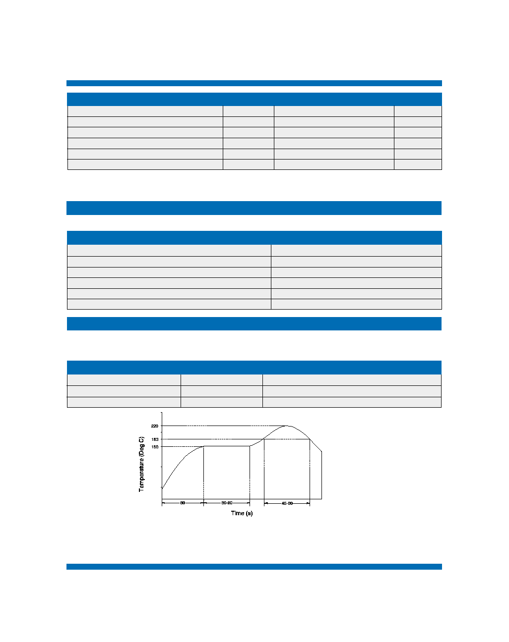
VI qualification includes aging at various extreme temperatures, shock and vibration, temperature cycling, and IR reflow
simulation. The conditions a device can withstand are well understood and devices can be subjected to the profile above. This
profile shows a ramp up condition to prevent thermal shock, a preheat period in which the flux is activated, a ramp up to 183∞C
which is the reflow temperature of Sn/Pb eutectic, and a gradual cool down. The time above 183∞C should not exceed 60
seconds and the peak temperature should be no more than 220∞C for 10 seconds. The VC-700's are hermetically sealed so
an aqueous wash is not an issue.
10188_VECTRON 05/21/03 3:14 PM Page 4
VC-700 Voltage Controlled Crystal Oscillator
Vectron International ∑ 267 Lowell Road, Hudson, NH 03051 ∑ Tel: 1-88-VECTRON-1 ∑ Web: www.vectron.com
5
155.520
156.250
161.1328
167.3316
Standard Frequencies (MHz)
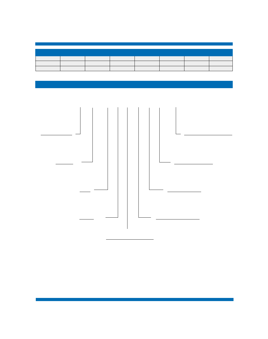
Ordering Information
Other frequencies available upon request
VC-700 - D F F - G F A - xxx.xxx
Product Family
VC: VCXO
Frequency (See Above)
77.6 - 180 MHz
Package
700: 5.0 x 7.5 x 2.8 mm
Linerarity, Stability
A: N/A
L: ± 10 linearity
M: ± 20 ppm stability
Input
C: 5.0Vdc ± 5%
D: 3.3 Vdc ± 5%
Enable - Disable
A: N/A
F: Pin 2
Output
F: Complementary
PECL
Absolute Pull Range *
F: ± 32 ppm
G: ± 50 ppm
Operating Temperature
C: 0 to 70∞C
F: -40 to 85∞C
* Consult factory for other possible APR levels.
10188_VECTRON 05/21/03 3:14 PM Page 5