
Vectron International 267 Lowell Rd, Hudson NH 03051-4916 Tel:1-88-VECTRON-1 e-mail: vectron@vectron.com
Product Data Sheet
Not Recommended For New Designs
VCO-600A
Voltage Controlled Saw Oscillator
The VCO600A Voltage Controlled SAW Oscillator
Features
�
Output Frequency @ 155 MHz to 1 GHz
�
Low jitter, 3pS rms for 622.080 MHz version and
6pS rms (typical) for 155 MHz version
�
Ideal for clock smoothing, frequency translation,
clock and data retiming applications
�
10K ECL, PECL logic levels with fast
transition times
�
Complementary outputs
�
Low profile, surface mount package
�
Output disable feature
�
Low-frequency clock through feature
�
Miniature hermetically sealed ceramic surface-
mount package (SO-28, approx.0.7in. x 0.3in)
Applications
�
OC192/OC48/OC12 Clock Smoothing
�
Frequency Translation
Description
The VCO600A is a SAW stabilized, voltage controlled
oscillator that operates at the fundamental frequency
of the internal SAW filter. This filter is a high stability,
high-Q quartz device that enables the circuit to
achieve low phase jitter performance over a wide
operating temperature range. The oscillator is housed
in a hermetically sealed 28-lead surface mount
package. It has a unique output disable and clock
through feature to facilitate on-board testing.
VCO-600A Voltage Controlled SAW Oscillator
Vectron International 267 Lowell Rd, Hudson NH 03051-4916 Tel:1-88-VECTRON-1 e-mail vectron@vectron.com
2
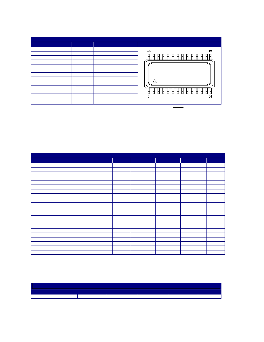
Pin Information
Table 1. Pin Function
Pin
Symbol
Function
Top View of Package
2,12,27 V
CC
Positive
Supply
4 CLKIN
1
Test Clock In
5,6,7,8 NC No
Connect
10 V
EE
Negative
Supply
17 V
BW
2
Modulation
Bandwidth
Adjust
19 V
C
Control
Voltage
21 OD
3
Output
Disable
23 CLKOUT
ECL
Output
25 CLKOUT
Complementary
ECLOutput
1,3,9,11,13,14,15,
16,18,20,22,24,26,28
GND
Case and Circuit
Ground
1. By setting OD low, a test signal may be applied at CLKIN and fed through the VCO-600A to both the CLKOUT and CLKOUT to facilitate on board
testing. The test signal input applied at CLKIN may be either an ECL or sinewave input (up to 1Vpp, AC coupled). CLKIN is biased internally to
VBB (Vcc-1.3V)
2. An optional capacitor to ground can be placed on VBW to reduce the modulation bandwidth for narrow bandwidth phase-lock loop applications. The
modulation bandwidth will be approximately 1/(12000*C)Hz, where C is equal to the capacitance in Farads. If the optional capacitor is not utilized, VBW
becomes a no connect (NC) and the modulation bandwidth will be approximately equal to the nominal device frequency
�
1200.
3. By setting OD low, the outputs are disabled and CLKOUT is held Low while CLKOUT is held High. The threshold for OD is 1.4V above VEE. OD
should not be driven above mid supply and during normal operation, should be left floating (use with an open collector or 3-State gate for interfacing with
standard logic). If the OD feature is used during normal operation, then CLKIN should be tied through 10K
to GND to avoid any possibility of chatter on
the CLKOUT outputs.
Performance Characteristics
Table 2. Electrical Performance
Parameter
Symbol
Minimum
Typical
Maximum
Units
Center Frequency, see ordering information
F
N
155
1000 MHz
Operating Temperature
T
OP
-40 25 +85
�C
Supply Current
I
EE
55 70 mA
Supply Voltage
1
V
EE
-4.5
-5
-5.5 V
Absolute Pull Range (Vc= -0.5 to -4.5)
APR
�
50
- -
ppm
Positive Gain Transfer (freq vs Vc) 155.520MHz
K
V
175 350 700
ppm/V
Positive Gain Transfer (freq vs Vc) 622.080MHz
K
V
60 135 290
ppm/V
Linearity Lin
�
3
%
Frequency Stability, -40 to 85 wrt 25
�
C
F
STAB
�
150
ppm
Output Level Low
2
V
OL
-1.95
-
-1.63 V
Output Level High
2
V
OH
-0.98
-
-0.75 V
Output Rise Time
3
t
R
100 250 400 pS
Output Fall Time
3
t
F
100 250 400 pS
Spurious Suppression
-50
-60
dB
Data Symmetry
SYM
45
49/51
55
%
Control Voltage Input Impedance
Z
c
8 10 12 K
Control Voltage Modulation Bandwidth
4
BW
-
500
-
kHz
Control Voltage Range
V
C
V
EE
- V
CC
V
Output Current
I
OUT
-
-
20 mA
Storage Temperature
T
S
-55
-
125 �C
Soldering Temp./Time
T
LS
-
- 240/10
�C/S
1. The VCO-600A may be configured for PECL operation. All outputs and inputs including V
C
are referenced to Vcc
2. Output Levels are standard 10K ECL and are fully 100K ECL compatible.
3. Transition times are measured from 20% to 80% of a full 10K ECL level swing.
4. The modulation bandwidth is a function of nominal center frequency and may be adjusted down through the use of an external capacitor on pin 17.
Please see Figure 1 and Figure 2 along with Notes 1, 2 and 3.
Table 3. Typical Single Side-Band Phase Noise (dBc/Hz)
Offset from Carrier
100 Hz
1 kHz
10
kHz
100 kHz
1 MHz
VCO600A 622.080
-50
-80
-110
-130
-145
VCO-600A Voltage Controlled SAW Oscillator
Vectron International 267 Lowell Rd, Hudson NH 03051-4916 Tel:1-88-VECTRON-1 e-mail vectron@vectron.com
3
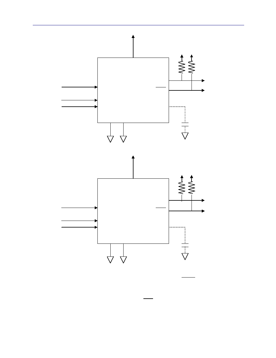
Figure 1. PECL Operation
Figure 2. ECL Operation
1. By setting OD low, a test signal may be applied at CLKIN and fed through the VCO-600A to both the CLKOUT and CLKOUT to facilitate on board
testing. The test signal input applied at CLKIN may be either an ECL or sinewave input (up to 1Vpp, AC coupled). CLKIN is biased internally to
VBB (Vcc-1.3V)
2. An optional capacitor to ground can be placed on VBW to reduce the modulation bandwidth for narrow bandwidth phase-lock loop applications. The
modulation bandwidth will be approximately 1/(12000*C) Hz, where C is equal to the capacitance in Farads. If the optional capacitor is not utilized, VBW
becomes a no connect (NC) and the modulation bandwidth will be approximately equal to the nominal device frequency
�
1200.
3. By setting OD low, the outputs are disabled and CLKOUT is held Low while CLKOUT is held High. The threshold for OD is 1.4V above VEE. OD
should not be driven above mid supply and during normal operation, should be left floating (use with an open collector or 3-State gate for interfacing with
standard logic). If the OD feature is used during normal operation, then CLKIN should be tied through 10K
to GND to avoid any possibility of chatter on
the CLKOUT outputs
17
V
EE
VCO-600A
OUT
Control Voltage
OUT
Output Disable
Test Clock In
V
CC Ground
-2V, 50ohms
-5 V
-4.5 to -0.5V
10
19
21
4
2,12,27
1,3,9,11,13,14,15,16,18,20,22,24,26,28
17
V
CC
VCO-600A
OUT
Control Voltage
OUT
Output Disable
Test Clock In
V
EE Ground
+3V, 50ohms
+5 V
0.5 to 4.5V
2,12,27
19
21
4
10
1,3,9,11,13,14,15,16,18,20,22,24,26,28
23
25
23
25
Optional
Capacitor
Reduces
Bandwidth
Optional
Capacitor
Reduces
Bandwidth
VCO-600A Voltage Controlled SAW Oscillator
Vectron International 267 Lowell Rd, Hudson NH 03051-4916 Tel:1-88-VECTRON-1 e-mail vectron@vectron.com
4
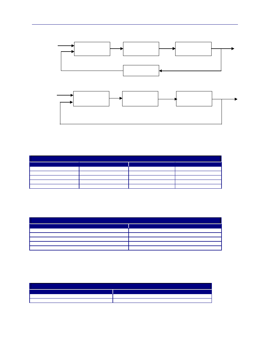
Figure 3. Typical Frequency Translation Diagram
Figure 4. Typical Clock Smoothing Diagram
Absolute Maximum Ratings
Stresses in excess of the absolute maximum ratings can permanently damage the device. Functional operation is not implied at
these or any other conditions in excess of conditions represented in the operational sections of this data sheet. Exposure to
absolute maximum ratings for extended periods may adversely affect device reliability.
Table 4. Absolute Maximum Ratings
Parameter
Symbol
Ratings
Unit
Power Supply
V
EE
-8 to 0
V
Output Current
1
Iout
20
mA
Output Current
2
Iout
50
mA
Voltage Control Range
1
V
C
V
EE
to V
CC
V
Voltage Control Range
2
V
C
V
EE
-0.5 to V
CC
+0.5 V
1 Limts beyond which performance can not be guarenteed.
2 Limits beyond which device life may be impaired.
Qualification Conformance
The VCO-600A family has undergone, and passed, the following Mil-Std qualification.
Table 5. Environmental Compliance
Parameter
Conditions
Mechanical Shock
MIL-STD-883C 2002.3, TEST A
Mechanical Vibration
MIL-STD-883C 2007.1, TEST A
Solderability
MIL-STD-883C 2003.5,
Gross and Fine Leak
MIL-STD-883C, 1014.7, 100% Tested
Resistance to Solvents
MIL-STD-883C 2016
Handling Precautions
Although ESD protection circuitrry has been designed into the the VCO-600A, proper precautions should be taken when handling
and mounting. VI employs a human body model and a charged-device model (CDM) for ESD susceptibility testing and design
protection evaluation. ESD thresholds are dependent on the circuit parameters used to define the model. Although no industry wide
standard has been adopted for the CDM, a standard HBM of resistance=1.5Kohms and capacitance = 100pF is widely used and
therefore can be used for comparison purposes.
Table 6. ESD Ratings
Model
Minimum
Human Body Model
1000 V
Charged Device Model
1000 V
and Freq
Detector
Loop Filter
VCO-600A
622.080MHz
Divide by 12
51.840MHz
622.080MH
155.52MHz
and Freq
Detector
Loop Filter
VCO-600A
155.520MHz
155.52MHz
VCO-600A Voltage Controlled SAW Oscillator
Vectron International 267 Lowell Rd, Hudson NH 03051-4916 Tel:1-88-VECTRON-1 e-mail vectron@vectron.com
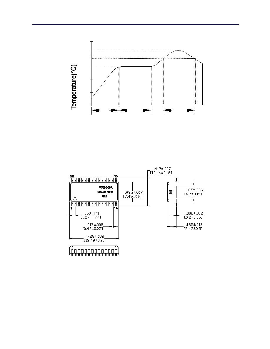
5
220
45-60s.
60-90s.
60s.
150
183
Time(s)
Figure 5. Suggested IR profile
Figure 6. Outline Diagram
VI
VCO-600A Voltage Controlled SAW Oscillator
Vectron International 267 Lowell Rd, Hudson NH 03051-4916 Tel:1-88-VECTRON-1 e-mail vectron@vectron.com
6
J
H
G
F
E
D
C
B
A
L
K
I
Bottom Holes for TRU
and VCO Products Only
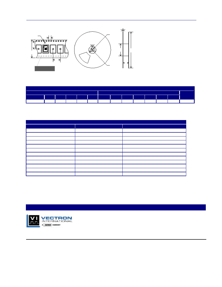
Figure 7. Tape Reel Drawing
Table 7. Tape and Reel Dimensions (mm)
Tape Dimensions
Reel Dimensions
# Per
Product
A
B
C
D
E
F
G
H
I
J
K
L
Reel
VCO600A
32
14.2
1.5 4 16 1.78 21 13 100 5 33 330
200
Ordering information
Table 8. Part number ordering information
Part Number
Packaging
Comcode
VCO600A 155.52MHz
Tube
107040537
VCO600A 155.52MHz
Tape and Reel
407611896
VCO600A 278.528MHz
Tube
107316457
VCO600A 278.852MHz
Tape and Reel
VCO600A 311.040MHz
Tube
107012551
VCO600A 311.040MHz
Tape and Reel
VCO600A 368.640MHz
Tube
107237539
VCO600A 368.640MHz
Tape and Reel
407875244
VCO600A 622.080MHz
Tube
107012569
VCO600A 622.080MHz
Tape and Reel
407961762
VCO600A 666.5143MHz
Tube
330016544
VCO600A 666.5143MHz
Tape and Reel
330018383
For Additional Information, Please Contact:
Vectron International reserves the right to make changes to the product(s) and or information contained herein without notice.
No liability is assumed as a result of their use or application. No rights under any patent accompany the sale of any such product(s) or information.
VCO600A.DOC (REVISION DATE: 11/23/04)
For Additional Information, Please Contact:
USA: Vectron International, 267 Lowell Rd, Hudson, NH 03051 . . . . Tel: 1-88-VECTRON-1
Fax: 1-888-FAX-VECTRON
EUROPE: . . . . . . . . . . . . . . . . . . . . . . . . . . . . . . . . . . . . . . . . . . . . . Tel: +49 (0) 3328-4784-17
Fax: +49 (0) 3328-4784-30
ASIA: . . . . . . . . . . . . . . . . . . . . . . . . . . . . . . . . . . . . . . . . . . . . . . . . . Tel: +86-21-28909740
Fax: +86-21-28909240