VCXO-2070S
www.vectron.com
USA: Vectron International ∑ 267 Lowell Road, Hudson, NH 03051 ∑ Tel: 1-88-VECTRON-1 ∑ Fax: 1-888-FAX-VECTRON
EUROPE: Tel: 49 (0) 3328 4784 17 ∑ Fax: 49 (0) 3328 4784 30
ASIA: Tel: +86 21 28909740 / 41 / 42 ∑ Fax: +86 21 28909240 / 2890999
Vectron International reserves the right to make changes to the product(s) and/or information contained herein without notice.
No liability is assumed as a result of their use or application.
No rights under any patent accompany the sale of any such product(s) or information.
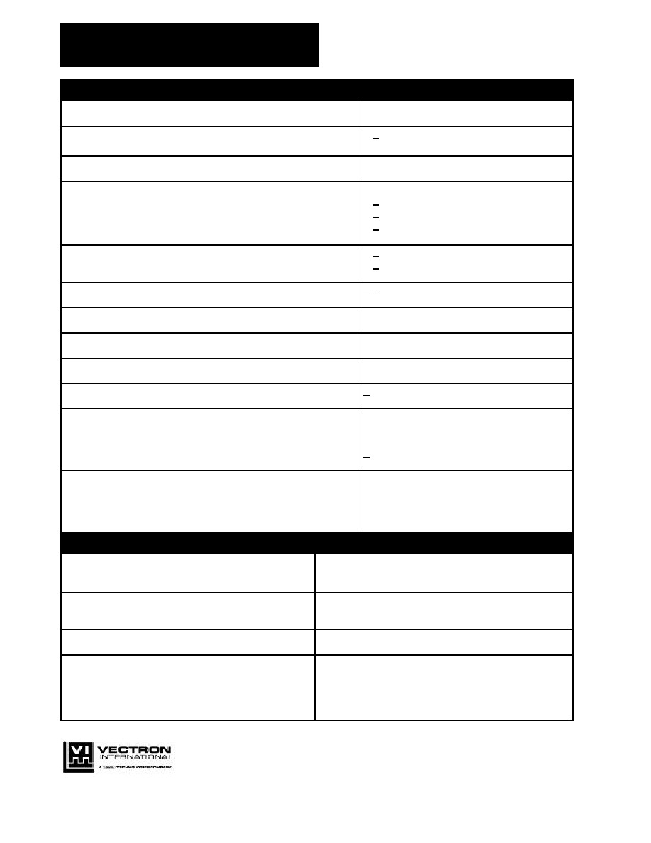
1. Specification
Nominal Frequency Range:
2 MHz to 32 MHz
Nominal freq. tolerance @ Uc = 2.5V, T = 25
±
3∞C:
< + 10 ppm
Frequency deviation after reflow and cooling to 25∞C:
<
±
3 ppm
Frequency stability
in the temperature range - 20∞C to + 70∞C:
vs. supply voltage changes U
B
±
5%:
vs. load changes
±
5%:
< + 15 ppm
< + 5 ppm
< + 5 ppm
Aging @ 25∞C :
< + 5 ppm / first year
< + 2 ppm / year in the following years
Frequency control range:
> + 100 ppm
Control voltage Uc :
0.5 V to 4.5 V
Transfer function / Linearity:
positive / 10%
Supply voltage U
B
:
5 V
±
5%
Current consumption:
< 25 mA
Output voltage :
load :
duty cycle :
rise time, fall time:
HCMOS
1 kOhm // 15 pF
40% / 60%
< 8 ns (load 1kOhm//15pF)
Temperature ranges
Operating:
Operable:
Storage:
-20∞C ... + 70∞C
-25∞C ... + 75∞C
-40∞C ... + 85∞C
2. Environmental conditions
Shock:
DIN IEC 68-2-27,Test Ea, 100 g, 6ms
Half-sine, 3 bumps in 3 main directions
Vibration:
DIN IEC 68-2-6, Test Fc, 10-500Hz, 10g,
2 h in 3 main directions
Humidity:
DIN IEC 68-2-3, 40∞C/93%RH, 21 days
Solderability:
DIN IEC 68-2-20 only for wire leads,
Methode 3: Solder globule at + 235∞C

VCXO-2070S
www.vectron.com
USA: Vectron International ∑ 267 Lowell Road, Hudson, NH 03051 ∑ Tel: 1-88-VECTRON-1 ∑ Fax: 1-888-FAX-VECTRON
EUROPE: Tel: 49 (0) 3328 4784 17 ∑ Fax: 49 (0) 3328 4784 30
ASIA: Tel: +86 21 28909740 / 41 / 42 ∑ Fax: +86 21 28909240 / 2890999
Vectron International reserves the right to make changes to the product(s) and/or information contained herein without notice.
No liability is assumed as a result of their use or application.
No rights under any patent accompany the sale of any such product(s) or information.
3. Marking
Manufacturer's name, date code(week/year);
Specification;
Center frequency
4. Case
Case style: BF 141
1.Pin configuration
1. Control voltage U
C
= 0.5V...4.5V
2. Ground, Case
3. RF-Output
4. Supply voltage U
B
5. Test circuit
V
A
O
O
O
B
GND
Oscilloscope,
Counter or
Spectrum
Analyzer
RE = 50 Ohm
975 Ohm
50 Ohm
+U
Oscillator
1
O
V
V
U_control
2
4
3
15 pF