 | –≠–ª–µ–∫—Ç—Ä–æ–Ω–Ω—ã–π –∫–æ–º–ø–æ–Ω–µ–Ω—Ç: VS-500A | –°–∫–∞—á–∞—Ç—å:  PDF PDF  ZIP ZIP |

Product Data Sheet
VS-500A
Voltage Controlled Saw Oscillator
Features
∑ Output Frequencies from 155 MHz to 800 MHz
∑ Low Jitter < 1 ps rms in the 12kHz to 20MHz range
∑ < 1ps rms jitter in 50kHz to 80MHz range
∑
3.3V (see VS-500) or 5.0V operation
∑ Ideal for clock smoothing, frequency translation, clock
and data retiming applications
∑ 10K ECL, PECL logic levels with fast transition times
∑ Complementary outputs
∑ Low profile, surface mount package
∑ Output disable feature
Applications
∑ 2.5, 10 Gbit/s FEC and standard SONET/SDH Clock
Smoothing and Frequency Translation
∑ 10 Gigabit Ethernet Clock Smoothing
∑ Frequency Translation
Description
The VS-500A is a SAW based voltage controlled
oscillator that operates at the fundamental frequency of
the internal SAW filter. This resonator is a high-Q quartz
device that enables the circuit to achieve low phase
jitter performance over a wide operating temperature
range. The oscillator is housed in a hermetically sealed
J-lead surface mount package offered on tape and reel.
It has an output disable to facilitate on-board testing.

VS-500A Voltage Controlled SAW Oscillator
Pin Information
Table 1. Pin Function
Performance Characteristics
Vectron International ∑
267 Lowell Road, Hudson, NH 03051 ∑ Tel: 1-88-VECTRON-1 ∑ Fax: 1-888-FAX-VECTRON
2
Pin
Symbol
Function
1 V
C
VCSO Control Voltage
2 OD
Output
Disable
3
GND
Case and electrical ground
4 Output
VCSO
Output
5
COutput
VCSO Complimentary Output
6 V
CC
Power Supply Voltage (5.0 V ±10%)
1. By setting OD low, the outputs are disabled and OUT is held high while Complementary OUT is held low. The threshold for Output Disable is 1.4V
above pin 3. Output Disable should not be driven above mid supply and during normal operation, should be left floating (use with an open collector or
3-State gate for interfacing with standard logic).
Parameter Symbol
Minimum
Typical
Maximum
Units
Center Frequency, see ordering information
F
N
155 800
MHz
Operating Temperature
T
OP
-40 25 +85
∞C
Supply Current (no load)
I
CC
55 70
mA
Supply Voltage
V
CC
4.5 5 5.5
V
Absolute Pull Range over -40 to 85∞C
APR
±50
-
-
ppm
(Vc= 0.5 to 4.5)
Positive Gain Transfer @ 155.52MHz
K
V
- 350 -
ppm/V
(Frequency vs Control voltage)
Positive Gain Transfer @ 622.080MHz
K
V
- 200 -
ppm/V
(Frequency vs Control voltage)
Linearity Lin
±3
%
Frequency Stability, -40 to 85 wrt 25∞C
F
STAB
±150 ppm
Output Level Low
1
V
OL
V
CC
-1.95 - V
CC
-1.63 V
Output Level High
1
V
OH
V
CC
-0.98 - V
CC
-0.75
V
Output Rise Time
2
t
R
250 400 ps
Output Fall Time
2
t
F
250
400 ps
Jitter @ 155.520 MHz, 12 KHz to 20 MHz
0.439
ps, rms
Jitter @ 622.080 MHz, 12 KHz to 20 MHz
0.276
ps, rms
Jitter @ 622.080 MHz, 50 KHz to 80 MHz
0.293
ps, rms
Spurious Suppression
-50
-60
dB
Data Symmetry
SYM
45
49/51
55
%
Control Voltage Input Impedance
Zc
8
10
12
K
Control Voltage Modulation Bandwidth
BW
-
500
-
kHz
Output Current
Iout
-
-
20
mA
Table 2. Electrical Performance @ 25∞C
1. Output Levels are standard 10K ECL and are fully 100K ECL compatible.
2. Transition times are measured from 20% to 80% of a full 10K ECL level swing.
Offset from Carrier
100 Hz
1kHz
10kHz
100kHz
VS-500A 622.080
-62
-85
-109
-127
Table 3. Typical Single Side-Band Phase Noise (dBc/Hz)
VS-500A Voltage Controlled SAW Oscillator
Vectron International ∑
267 Lowell Road, Hudson, NH 03051 ∑ Tel: 1-88-VECTRON-1 ∑ Fax: 1-888-FAX-VECTRON
3
4
5
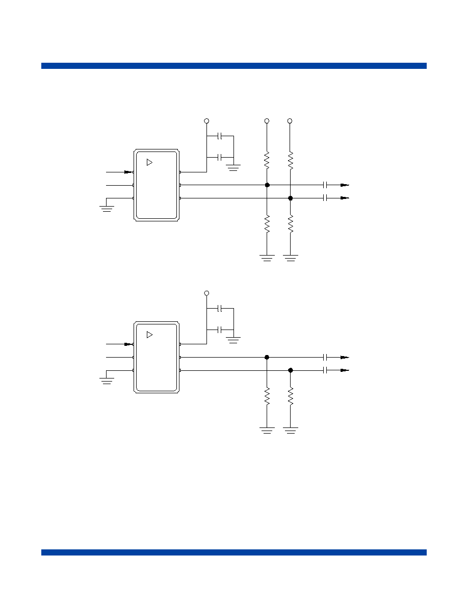
Output
6
COutput
Vcc
Vc
1
OD
2
3
Gnd
+5.0V
120
120
82
82
.01uF
.1uF
+5.0V
+5.0V
(From PLL)
Vcc
COutput
Output
(From PLL)
OD
3
Gnd
2
4
5
Vc
1
6
330
330
.1uF
.01uF
+5.0V
(AC Coupling)
(AC Coupling)
Note 2: To diasble output, connect Output Disable to ground. To enable output, leave pin 2 floating or open.
Figure 1
PECL Operation

VS-500A Voltage Controlled SAW Oscillator
Vectron International ∑
267 Lowell Road, Hudson, NH 03051 ∑ Tel: 1-88-VECTRON-1 ∑ Fax: 1-888-FAX-VECTRON
4
4
5
Output
6
COutput
Vcc
Vc
1
OD
2
3
Gnd
-5.0V
120
120
80
80
-5.0V
(From PLL)
Vcc
COutput
Output
(From PLL)
OD
3
Gnd
2
4
5
Vc
1
6
330
330
(AC Coupling)
(AC Coupling)
.01uF
0.1uF
-5.0V
-5.0V -5.0V
-5.0V
.01uF
0.1uF
Note1: Conductive lid will be @ -5V for ECL configuration
Note 2: To diasble output, connect Output Disable to ≠5V. To enable output, leave pin 2 floating or open.
Figure 2. ECL Operation

VS-500A Voltage Controlled SAW Oscillator
Vectron International ∑
267 Lowell Road, Hudson, NH 03051 ∑ Tel: 1-88-VECTRON-1 ∑ Fax: 1-888-FAX-VECTRON
Absolute Maximum Ratings
Stresses in excess of the absolute maximum ratings can permanently damage the device. Functional operation is not implied at these or any
other conditions in excess of conditions represented in the operational sections of this data sheet. Exposure to absolute maximum ratings for
extended periods may adversely affect device reliability.
Parameter Symbol Ratings
Unit
Power Supply
V
CC
0 to 8
V
Output Current
1
Iout
20 mA
Output Current
2
Iout 50
mA
Voltage Control Range
1
V
C
0 to V
CC
V
Voltage Control Range
2
V
C
-0.5 to V
CC
+0.5 V
Storage Temperature
T
S
-55 to 125
∞C
Soldering Temp./Time
T
LS
220/10
∞C/Seconds
Table 4. Absolute Maximum Ratings
1 Limts beyond which performance can not be guaranteed.
2 Limits beyond which device life may be impaired.
Parameter Conditions
Mechanical Shock
MIL-STD-883, Method 2002
Mechanical Vibration
MIL-STD-883, Method 2007
Solderability
MIL-STD-883, Method 2003
Gross and Fine Leak
MIL-STD-883, Method 1014
Resistance to Solvents
MIL-STD-883, Method 2016
Qualification Conformance
The VS-500A family passes the following Mil-Std qualification.
Table 5. Environmental Compliance
5