PRELIMINARY
Vicor Corporation
Tel: 800-735-6200
VICBrick DC-DC Converter
Rev. 1.5
Page 1 of 14
vicorpower.com
Absolute Maximum Ratings
Parameter
Typ
Unit
VICBrick to ambient; 0 LFM
8.0
∞C/W
VICBrick to ambient; 200 LFM
6.0
∞C/W
Thermal capacity
22.8
Ws/∞C
Thermal Resistance and Capacity
Features
∑ Up to 80 A continuous, 100 A surge
∑ 93% efficiency @ 5 Vdc
∑ 100∞C operating case temperature
∑ 180 W/in
3
power density 120 A/in
3
∑ 36 ≠ 75 Vdc input range
∑ 100 V input surge for 100 ms
∑ Low noise ZCS/ZVS architecture
∑ Fast dynamic response
∑ Parallelable, with fault tolerance
∑ 2,250 Vdc basic insulation
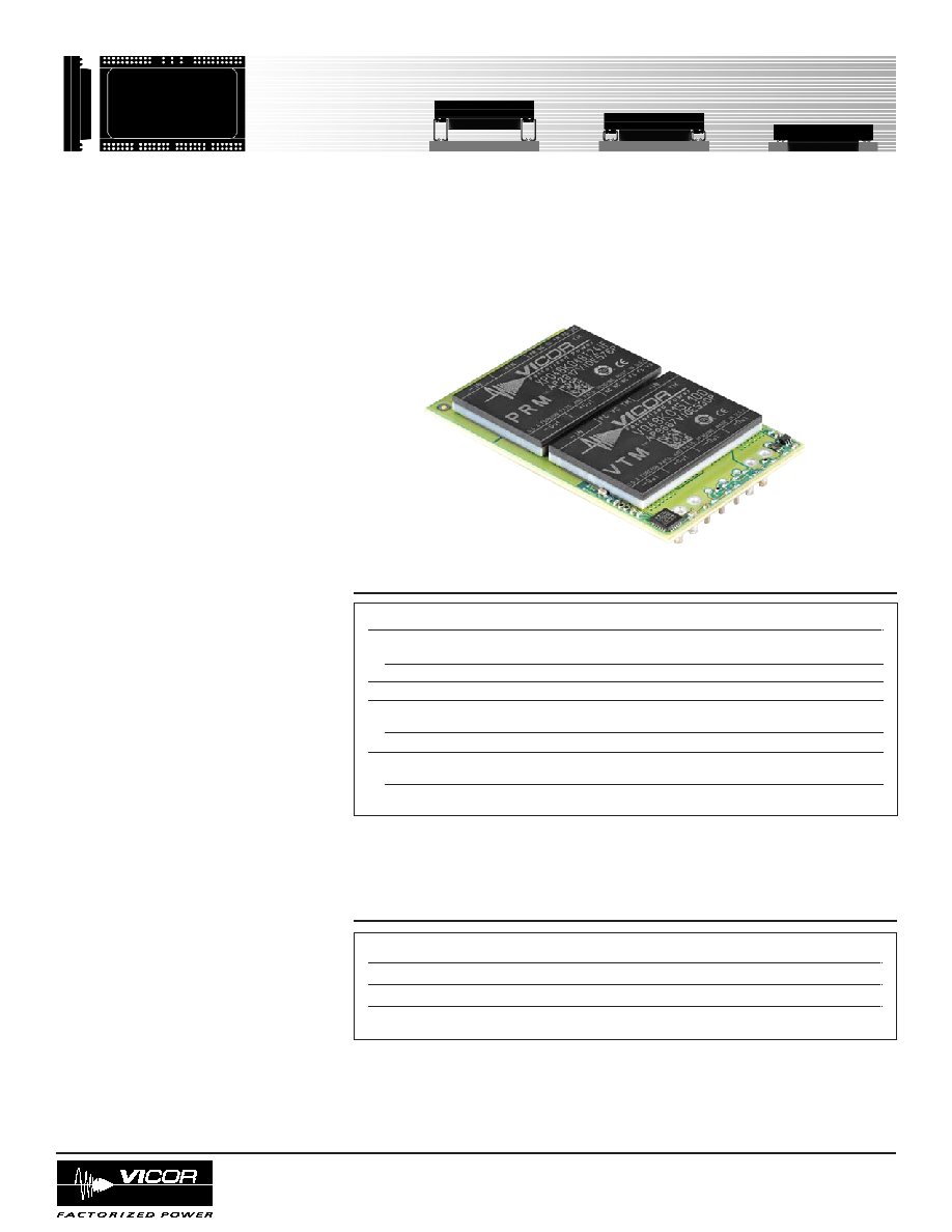
Product Overview
VICBrick high-density converters (up to
120 A/in
3
) are enabled by Vicor's V∑I Chip
technology. Each VICBrick consists of two
V∑I Chips: a 36 ≠ 75 Vdc input Pre-Regulator
Module (PRM) that is paired with an
appropriate Voltage Transformation Module
(VTM) chosen to provide the desired output
voltage. While the ultra-low profile package
conforms to industry-standard quarter-brick
footprint (1.45" x 2.28"), it stands only
0.27" high and achieves 80 A of output current.
Standard outputs include 1.0, 1.2, 1.5 V and
1.8 V at 80 A, 2.5 V at 60 A, 3.0 and 3.3 V
at 45 A, and 5 V at 30 A. Output voltages
can be easily trimmed up or down over a
wide range. Dual output pins are used for
output currents over 50 A.
Utilizing breakthrough Sine Amplitude
Converter (SAC) technology, VICBricks
offer the highest efficiency, lowest noise,
fastest transient response and highest power
density. And because of the V∑I Chips
highly integrated functionality, VICBricks
have only a fraction of the parts of a typical
DC-DC converter.
Parameter
Rating
Unit
Notes
+In to ≠In voltage
Continuous
-1.0 to +75.0
Vdc
Surge
100
Vdc
<100ms
On/Off to ≠In voltage
-0.6 to +7.0
Vdc
Isolation voltage
Basic insulation
Input to output
2,250
Vdc
Operating case temperature
-40 to +100
∞C
Output side of VTM
Pin soldering temperature
Wave
500 (260)
∞F (∞C)
<5 sec
Hand
750 (390)
∞F (∞C)
<7 sec
V∑I Chip
TM
VICBrick
DC-DC Converters
Quarter Brick, 48 Vin Family
1.0 to 5.0 Vdc Output
VICBrick
PRELIMINARY
Vicor Corporation
Tel: 800-735-6200
VICBrick DC-DC Converter
Rev. 1.5
Page 2 of 14
vicorpower.com
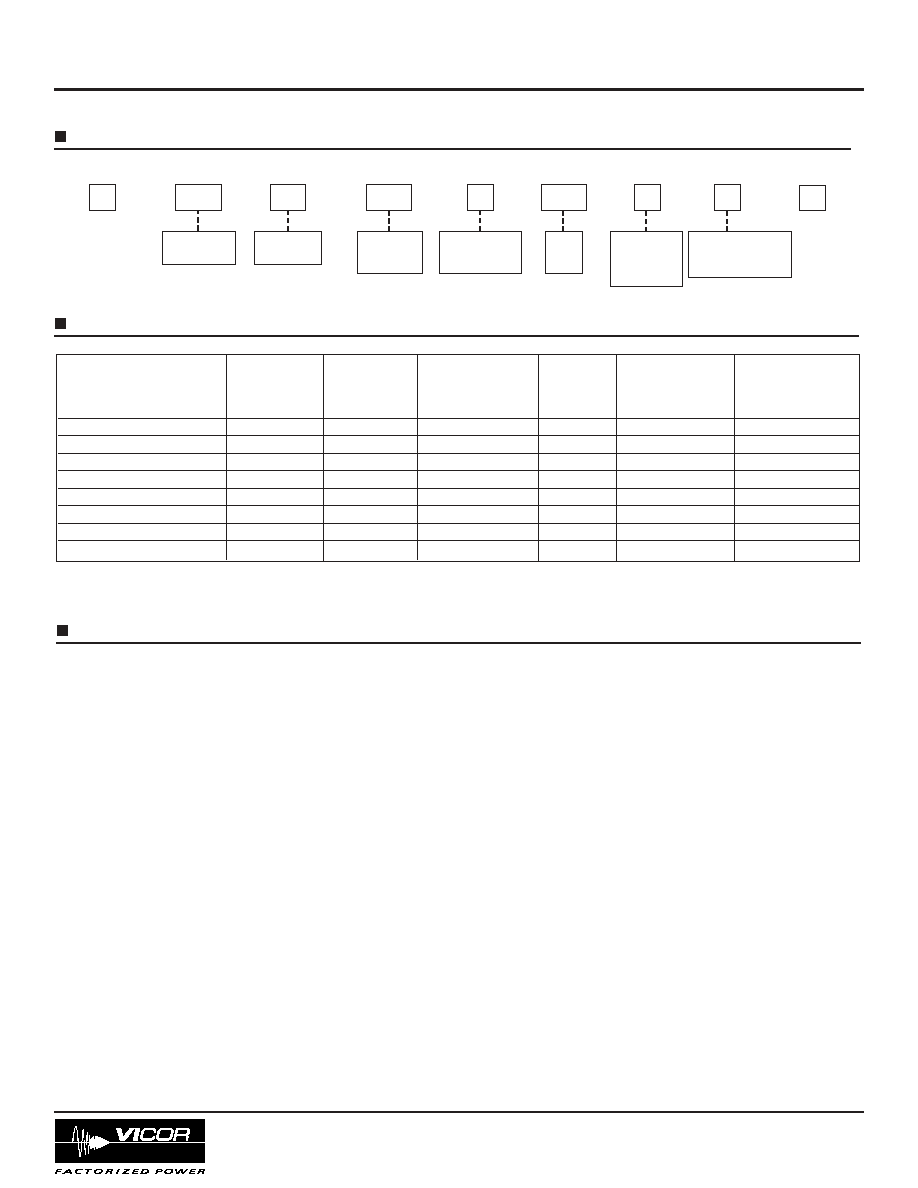
PART NUMBERING
Nominal
Input Voltage
Nominal
Output
Voltage (x10)
C = 1/4 Brick
Product
Grade
T= -40 to 125∞C
Package Style
1 = Single output pins
2 = Dual output pins
(see page 3)
Enable
Polarity
P="+"
M="≠"
(see page 7)
Output
Power
(x 0.1)
Model Number
Input
Output
Max Continuous
Typical
Output Voltage
Voltage
Voltage
Output Current
Full Load
Trim Range
Fuse Value
(Vdc)
(Vdc)
(Amps)
Efficiency
(Vdc)
D048C010T010M2N
36 ≠ 75
1.0
80*
83
0.90 ≠ 1.10
5.0 A
D048C012T012M2N
36 ≠ 75
1.2
80*
84
1.08 ≠ 1.32
6.3 A
D048C015T012M2N
36 ≠ 75
1.5
80
87
1.35 ≠ 1.65
6.3 A
D048C018T014M2N
36 ≠ 75
1.8
80
88
1.62 ≠ 1.98
6.3 A
D048C025T015M2N
36 ≠ 75
2.5
60
89
2.25 ≠ 2.75
7.0 A
D048C030T014M1N
36 ≠ 75
3.0
45
90
2.70 ≠ 3.30
8.0 A
D048C033T015M1N
36 ≠ 75
3.3
45
91
2.97 ≠ 3.63
7.0 A
D048C050T015M1N
36 ≠ 75
5.0
30
93
4.50 ≠ 5.50
7.0 A
PRODUCT MATRIX
D
048
C
030
T
014
M
2
N
INPUT FUSING
VICBricks are not internally fused in order to provide flexibility in power system configuration. Input line fusing of VICBricks
must always be incorporated within the power system. The input line fuse should be placed in series with +IN. Vicor recommends
using the Littlefuse Nano 451/453 series for fusing VICBricks. Please refer to the chart above for appropriate fuse values.
Specifications
* 100 A for 100 ms
PRELIMINARY
Vicor Corporation
Tel: 800-735-6200
VICBrick DC-DC Converter
Rev. 1.5
Page 3 of 14
vicorpower.com
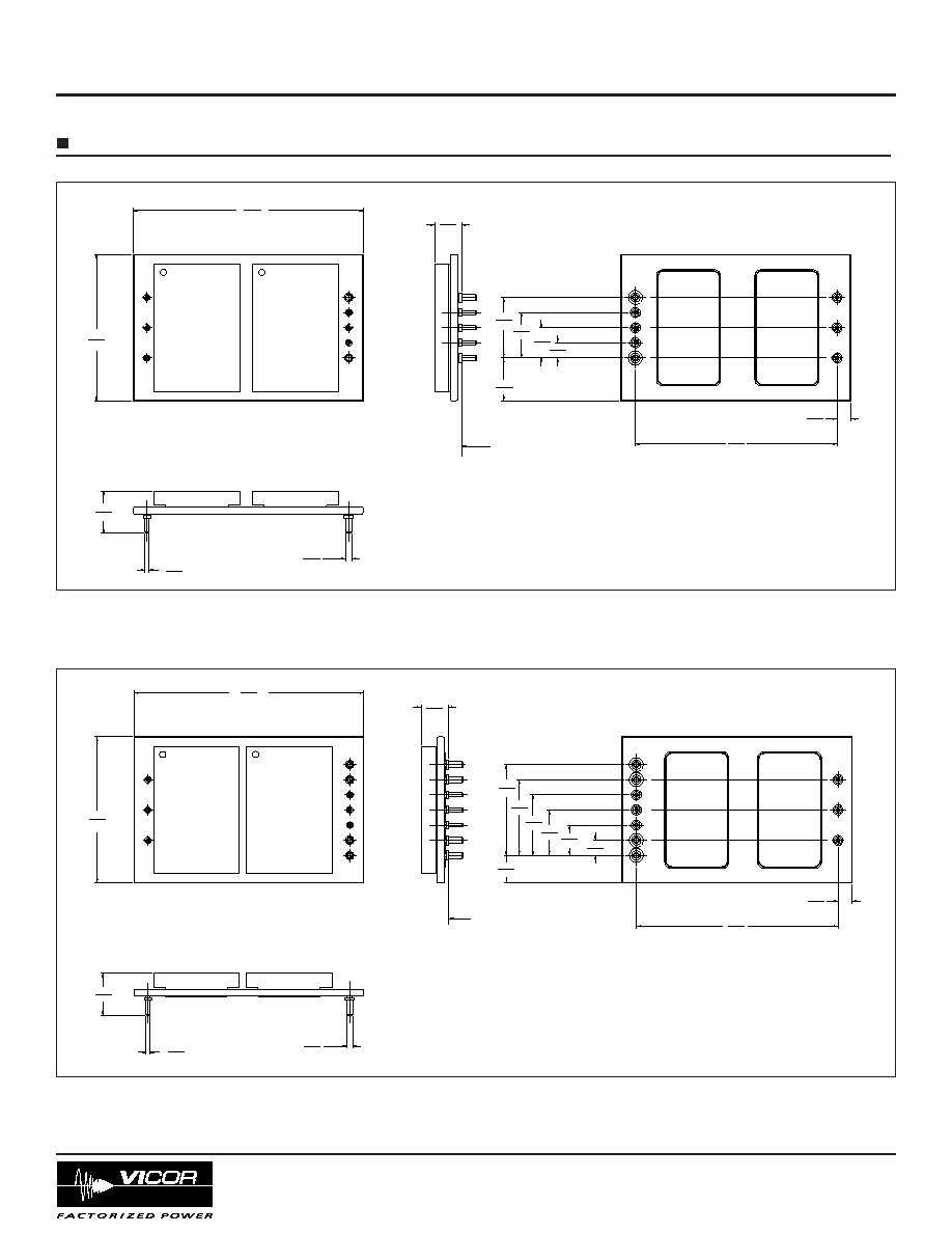
MECHANICAL DRAWINGS
57.9
2.28
36.8
1.45
(-)OUT
ON/OFF
(-)IN
(+)IN
(-)SENSE
TRIM
(+)SENSE
(+)OUT
TOP VIEW (COMPONENT SIDE)
6.8
0.27
SEATING PLANE
10.6
0.42
1.02
0.040
(6)PL.
1.52
0.060
(2)PL.
10.8
0.42
3.81
0.150
7.62
0.300
11.43
0.450
15.24
0.600
3.6
0.14
50.8
2.00
BOTTOM VIEW
¯
¯
NOTES:
1. DIMENSIONS ARE: mm/INCH.
2. UNLESS OTHERWISE SPECIFIED, TOLERANCES ARE:
.X/.XX=
±
0.5/0.02,
.XX/.XXX=
±
0.25/0.010
57.9
2.28
36.8
1.45
(-)OUT
(-)OUT
ON/OFF
(-)IN
(+)IN
(-)SENSE
TRIM
(+)SENSE
(+)OUT
(+)OUT
TOP VIEW (COMPONENT SIDE)
6.8
0.27
SEATING PLANE
10.6
0.42
1.02
0.040
(6)PL.
1.52
0.060
(4)PL.
7.0
0.27
7.62
0.300
11.43
0.450
15.24
0.600
19.05
0.750
22.86
0.900
3.81
0.150
3.6
0.14
50.8
2.00
BOTTOM VIEW
¯
¯
NOTES:
1. DIMENSIONS ARE: mm/INCH.
2. UNLESS OTHERWISE SPECIFIED, TOLERANCES ARE:
.X/.XX=
±
0.5/0.02,
.XX/.XXX=
±
0.25/0.010
Figure 1-- Mechanical outline and PCB footprint information; single output pin version (package style 1)
Figure 2-- Mechanical outline and PCB footprint information; dual output pin version (package style 2)
Specifications, continued
PRELIMINARY
Vicor Corporation
Tel: 800-735-6200
VICBrick DC-DC Converter
Rev. 1.5
Page 4 of 14
vicorpower.com
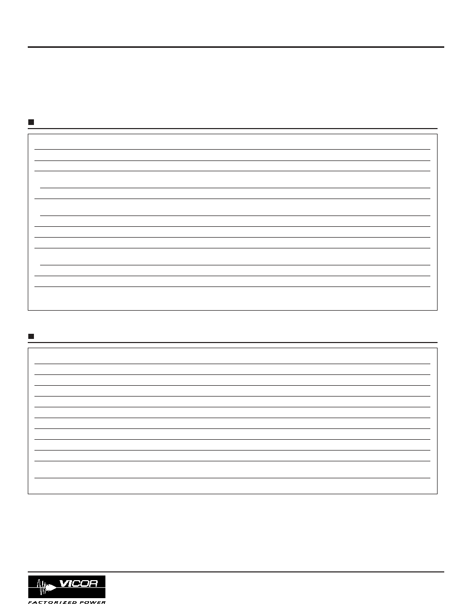
Parameter
Min
Typ
Max
Unit
Notes
Operating input voltage
36
48
75
Vdc
Input surge withstand
100
Vdc
<100 ms
Undervoltage
Turn-on
35
36
Vdc
Turn-off
32.6
33.8
Vdc
Overvoltage
Turn-off
76.0
Vdc
Turn-on
75.0
Vdc
Input reflected ripple current
3
% Iin
mA p-p (see Fig.3 for test circuit)
Input dV/dt
10
V/µs
Turn-on time
Power up
150
ms
ON/OFF enable
6
ms
No load power dissipation
6.0
W
Recommended external
10
50
µF
200 nH maximum source inductance
input capacitance
INPUT SPECIFICATIONS
Parameter
Min
Typ
Max
Unit
Notes
Output voltage accuracy
±1
%
48 V input; no load; 25∞C
Current limit
125
%
Average short circuit current
200
mA
Efficiency
Module dependent, see charts for individual models
Output OVP setpoint
120
%
Line regulation
0.1
%
Load regulation
0.1
%
Temperature regulation
±0.05
% / ∞C
Ripple and noise, p-p
Module dependent, see charts for individual models
Transient response
No load - full load step change, see note 1 below
Voltage deviation
2
%
Recovery time
75
µs
OUTPUT SPECIFICATIONS
Electrical characteristics apply over the full operating range of input voltage, output load (resistive) and case temperature,
unless otherwise specified.
Note 1: For important information relative to applications where the unit is subjected to continuous dynamic loading, contact Vicor
Applications Engineering at 800-927-9474.
Specifications, continued
PRELIMINARY
Vicor Corporation
Tel: 800-735-6200
VICBrick DC-DC Converter
Rev. 1.5
Page 5 of 14
vicorpower.com
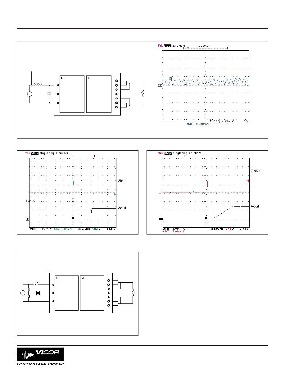
+
_
48 V
100
µ
F
Full
Load
Input reflected
ripple measurement point
1.5
µ
H
Example filter for low input reflected ripple
Input reflected current at full load and 48 Vin
Peak-to-peak 36 mA
Figure 4--Output turn-on waveform with input turn-on at
full load and 48 Vin
Figure 5-- Output voltage turn-on waveform with ON/OFF
enable at full load and 48 Vin.
+
_
Full
Load
P-configuration (positive logic) VICBrick
+In
≠In
ON/OFF
+Out
≠Out
Figure 6--Test circuit for measuring turn-on times
Figure 3--Typical input reflected ripple, and example input filter design
Specifications, continued