
Product Highlights
The MI-J00 family of miniaturized
DC-DC converters is designed for
military applications utilizing
distributed power architectures.
Based on Vicor's 1st Generation
family of zero-current/zero-voltage
switching, component-level,
DC-DC converters, the MI-J00
family offers state-of-the-art
performance in terms of power
density, efficiency, noise, ease of
use, and reliability.
The MI-J00 family is designed to
exceed all steady-state, transient
and under/overvoltage
requirements of MIL-STD-704D/E
for both 28Vdc input (MI-J20) and
270Vdc input (MI-J60), and the
worst case envelope of DOD-STD-
1399A for 155Vdc input.
The output voltage can be externally
trimmed or programmed from
50% to 110% of nominal output.
Current limiting, remote sense,
and an inhibit pin all combine to
offer a high degree of protection,
versatility, and reliability for
military power systems.
All units are manufactured
in ISO 9001-registered facilities.
Full epoxy encapsulation in
Vicor's industry standard
package enables the MI-J00
family units to meet MIL-STD-810
environmental testing
requirements for humidity,
fungus, salt fog, explosive
atmosphere, acceleration,
vibration, and shock. (See page 32.)
MI-J00
TM
Military DC-DC Converters 10 to 50W
Inputs:
28Vdc per MIL-STD-704D/E
155Vdc per MIL-STD-1399A
270Vdc per MIL-STD-704D/E
Single output: 2 ≠ 48Vdc
Up to 23W/in
3
MIL-STD-810 environments
Up to 90% efficiency
Remote sense
Current limit
ZVS/ZCS power architecture
Low noise FM control
Size: 2.28" x 2.4" x 0.5"
(57,9 x 61,0 x 12,7mm)
PARAMETER
MIN
TYP
MAX
UNITS
TEST CONDITIONS
Input Characteristics
Input voltage range
See input voltage chart
No load power dissipation
1.35
2.0
Watts
Output Characteristics
Set point accuracy
0.5
1.0
% Vnom
Load/line regulation
0.05
0.2
% Vnom
LL to HL, 10% to FL
0.2
0.5
% Vnom
LL to HL, NL to 10%
Output temperature drift
0.01
0.02
%/∞C
Output noise - pp
1.0
1.5
% Vnom
Whichever is greater
100
150 mV 20MHz
BW
Output voltage trimming
(1)
50
110
% Vnom
Remote sense compensation
0.5
Vdc
OVP set point
N/A
Current limit
105
125
% Inom
Auto restart
Short circuit current
105
130
% Inom
Control Pin Characteristics
Gate-in high threshold
6
Vdc
Gate-in low threshold
0.65
Vdc
Gate-in low current
6
mA
Isolation Characteristics
Isolation (input to output)
3,000
Vrms
Isolation (output to baseplate)
500
Vrms
Isolation (input to baseplate)
1,500
Vrms
Input/output capacitance
50
75
pF
Environmental (MIL-STD-810)
Altitude - method 500.2
70,000
feet
Procedure II
Humidity - method 507.2
86/240
% /hours
Procedure 1, cycle 1
Acceleration - method 513.3
9
g's
Procedure 2
Vibration - method 514.3
20
g's
Procedure 1, category 6
Shock - method 516.3
40
g's
Procedure 1
Reliability (MIL-HDBK-217F)
25∞C Ground Benign: G.B.
2,871,050
hours
50∞C Naval Sheltered: N.S.
667,568
hours
65∞C Airborne Inhabited Cargo: A.I.C.
559,855
hours
Thermal Characteristics
Efficiency
80-90
%
Baseplate to sink
0.14
∞C/W
With thermal pads
Thermal shutdown
N/A
Baseplate operating temperature
+100
∞C
See product grade
Storage temperature
+125
∞C
See product grade
Mechanical Specifications
Weight
3.0 (85)
ounces (grams)
Converter Specifications
(At TBP = 25∞C, nominal line and 75% load, unless otherwise specified)
(1)
10V, 12V, and 15V outputs, standard trim range ±10%. Consult factory for wider trim range.
}
Features
MI-J00 10/02 1 of 2
Configuration Chart
MI - J
-
Semi-custom modules available:
Consult factory.
(1) 16V operation at 75% load.
(2) These units rated at 75%
load from 125-150Vin:
MI-J6Z-xY
MI-J6Y-xY
MI-J60-xY
28Vdc input per MIL-STD 704D/E
155Vdc input per DOD-STD-1399A
270Vdc input per MIL-STD-704D/E
Product Grade Specifications
5
6
7
8
9
4
3
2
1
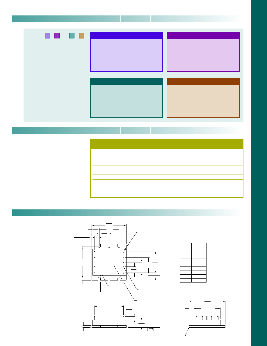
0.080 Dia (2) places
Solder plate
over copper alloy
0.040 (1,0) Dia (7) places
Solder plate
over copper alloy
.01
Aluminum Base
Product ID
this surface
Function
+In
≠In
+Out
Trim
≠Sense
≠Out
Pin #
1
2
3
4
5
6
7
8
9
FULL R
+0.030 (0,76)
-0.000 (0)
(5,6) Min.
(7,6) Min.
(44,4) Max.
2.40
2.28
0.12
0.50
1.90
0.65
(16,5)
0.49
(12,4)
0.30
±
0.015
(7,6)
±
(0,38)
0.15
2.10
(53,4)
1.30
0.40
(10,2)
0.35
±
0.015
(8,9)
±
(0,38)
1.40
(35,6)
1.00
(25,4)
0.70
(17,8)
Gate In
Gate Out
+Sense
MI-J00
(57,9)
(33,0)
(3,8)
0.15
(3,8)
0.30
(61,0)
1.75
(48,3)
0.22
(3,0)
(12,7)
*Test data available for review or download from vicorpower.com
Mechanical Drawing
Output Power/Current
5V
<5V
A
=
10W
--
o
Z
=
25W
5A
Y
=
50W
10A
Product Grade
Operating Temp.
I =
-40∞C to +100∞C
M
=
-55∞C to +100∞C
PARAMETER
PRODUCT GRADE
I - Grade M - Grade
Storage temperature
-55∞C to +125∞C
-65∞C to +125∞C
Operating temperature (baseplate)
-40∞C to +100∞C
-55∞C to +100∞C
Power cycling burn-in
12 hours, 25 cycles
96 hours, 200 cycles
Temperature cycled with power off
48 hours, 12-16 cycles
48 hours, 12-16 cycles
-55∞C to +100∞C
-65∞C to +100∞C
Test data supplied at these temperatures*
-40∞C, +80∞C
-55∞C, +80∞C
Warranty
2 years
2 years
Environmental compliance
MIL-STD-810
MIL-STD-810
Derating
NAVMAT P-4855-1A
NAVMAT P- 4855-1A
Input Voltage
Nominal
Range
Transient
2 =
28V
18 ≠ 50V
(1)
60V
5 = 155V
100 ≠ 210V
230V
6 = 270V
125 ≠ 400V
(2)
475V
7 = 165V
100 ≠ 310V
Output Voltage
Z = 2V
T = 6.5V
N = 18.5V
Y = 3.3V
R = 7.5V
3 = 24V
0 = 5V
M= 10V
L = 28V
X = 5.2V
1 = 12V
J = 36V
W= 5.5V
P = 13.8V
K = 40V
V = 5.8V
2 = 15V
4 = 48V
MI-J00 10/02 1 of 2