 | –≠–ª–µ–∫—Ç—Ä–æ–Ω–Ω—ã–π –∫–æ–º–ø–æ–Ω–µ–Ω—Ç: uRAM3C21 | –°–∫–∞—á–∞—Ç—å:  PDF PDF  ZIP ZIP |

Set your site on VICOR at www.vicorpower.com
PRELIMINARY
Vicor Corp. Tel: 800-735-6200, 978-470-2900 Fax: 978-475-6715
MicroRAM
Rev. 1.1
Page 1 of 8
Features
∑
>40dB ripple attenuation from
60Hz to 1MHz
∑
Integrated OR'ing diode supports
N+1 redundancy
∑
Significantly improves load
transient response
∑
Efficiency up to 98%
∑
User selectable performance optimization
∑
Combined active and passive filtering
∑
3-30Vdc input range
∑
20 and 30 Ampere ratings
Product Highlights
Vicor's MicroRAM output ripple attenuation
module combines both active and passive
filtering to achieve greater than 40dB of
noise attenuation from 60Hz to 1Mhz. The
MicroRAM operates over a range of 3 to
30Vdc, is available in either 20 or 30A
models and is compatible with most
manufacturers switching converters
including Vicor's 1st and 2nd Generation
DC-DC converters.
The MicroRAM's closed loop architecture
greatly improves load transient response and
with dual mode control, insures precise point
of load voltage regulation, The MicroRAM
supports redundant and parallel operation
with its integrated OR'ing diode function.
It is available in Vicor's standard micro
package (quarter brick) with a variety of
terminations for through hole, socket or
surface mount applications.
Data Sheet
MicroRAM
TM
Output Ripple Attenuation Module
4
5
Shown actual size:
2.28 x 1.45 x 0.5 in
57,9 x 36,8 x 12,7 mm
Absolute Maximum Ratings
Thermal Resistance
Parameter
Typ
Unit
Baseplate to sink; flat, greased surface
0.16
∞C/Watt
Baseplate to sink; with thermal pad (P/N 20264)
0.14
∞C/Watt
Baseplate to ambient
8.0
∞C/Watt
Baseplate to ambient; 1000 LFM
1.9
∞C/Watt
uRAM
2
C
2
1
Product
Baseplate
1 = Slotted
2 = Threaded
3 = Thru-hole
Pin Style*
1 = Short Pin
2 = Long Pin
S = Short ModuMate
N = Long ModuMate
Product Grade
C = ≠20∞C to +100∞C
T = ≠40∞C to +100∞C
H = ≠40∞C to +100∞C
M = ≠55∞C to +100∞C
Type
2 = 20A
3 = 30A
Part Numbering
*Pin styles S & N are compatible with the ModuMate interconnect system for socketing and surface mounting.
Patents Pending
Parameter
Rating
Unit
Notes
+In to ≠In
30
Vdc
Continuous
+In to ≠In
40
Vdc
100ms
Load current
40
Adc
Continuous
Ripple Input (Vp-p)
100
mV
60Hzc100 kHz
Ripple Input (Vp-p)
500
mV
100kHz ≠2MHz
Mounting torque
4-6 (0.45-0.68)
In. lbs (Nm)
6 each, 4-40 screw
Pin soldering temperature
500 (260)
∞F (∞C)
5 sec; wave solder
Pin soldering temperature
750 (390)
∞F (∞C)
7 sec; wave solder
Storage temperature (C, T-Grade)
-40 to +125
∞C
Storage temperature (H-Grade)
-55 to +125
∞C
Storage temperature (M-Grade)
-65 to +125
∞C
Operating temperature (C-Grade)
-20 to +100
∞C
Baseplate
Operating temperature (T, H-Grade)
-40 to +100
∞C
Baseplate
Operating temperature (M-Grade)
-55 to +100
∞C
Baseplate

Vicor Corp. Tel: 800-735-6200, 978-470-2900 Fax: 978-475-6715
MicroRAM Data Sheet
Rev. 1.1
Page 2 of 8
Set your site on VICOR at www.vicorpower.com
PRELIMINARY
Parameter
Min
Typ
Max
Unit
Notes
Operating current range
No internal current limiting. Converter input must be
µRAM2xxx
0.02
20
A
properly fused such that the µRAM output current
µRAM3xxx
0.02
30
A
does not exceed the maximum operating current
rating by more than 30% under a steady state condition.
Operating input voltage
3.0
30
Vdc
Continuous
Transient output response
50
mVp-p
Step load change;
Load current step <1A/µsec
see Figures 9, 12, & 15, pp. 6-7
Transient output response
Optional capacitance C
TRAN
can be used
Load current step <1A/µsec
50
mVp-p
to increase transient current capability; See Figures
(C
TRAN
= 820µF)
1 & 2 on p. 3 and Figures 10, 13, & 16 on pp. 6-7
V
HR
headroom voltage range
(1)
See Figures 5, 6 & 7
@ 1A load
325
425
mV
See Table 1 for headroom setting resistor values
Output ripple
10
mVp-p
Ripple frequency 60Hz to 100kHz; optional capacitor
Input Vp-p = 100mV
5
mVrms
C
HR
= 100µF required to increase low frequency
attenuation as shown in Figures 3a and 3b
see Figures 8, 11, & 14, pp. 6-7
Output ripple
10
mVp-p
Ripple frequency 100kHz to 2MHz;
Input Vp-p = 500mV
5
mVrms
see Figures 8, 11, & 14, pp. 6-7
SC output voltage
(2)
1.23
Vdc
See Table 1 R
SC
value
OR'ing threshold
10
mV
Vin ≠ Vout
µRAM bias current
60
mA
Power Dissipation
µRAM2xxx V
HR
= 380mV@1A
7.5
W
Vin = 28V; Iout = 20A
µRAM3xxx V
HR
= 380mV@1A
11.5
W
Vin = 28V; Iout = 30A
µRAM MODULE SPECIFICATIONS (-20∞C to +100∞C baseplate temperature)
Electrical Characteristics
Electrical characteristics apply over the full operating range of input voltage, output power and baseplate temperature, unless
otherwise specified. All temperatures refer to the operating temperature at the center of the baseplate.
(1)
Headroom is the voltage difference between the +Input and +Output pins.
R
HR
= (µRAM +Out/V
HR
) x 2.3k (see Table 1 for example values)
(2)
SC resistor is required to trim the converter output up to accommodate the headroom of the µRAM module when remote sense
is not used. This feature can only be used when the trim reference of the converter is in the 1.21 to 1.25 Volt range.
(see Table 1 with calculated R
SC
resistor values)
R
SC
= ((µRAM +Out)/1.23V x 1k) ≠ 2k
µRAM Out
3.0V
5.0V
12.0V
15.0V
24.0V
28.0V
V
HR
@ 1A
375mV
375mV
375mV
375mV
375mV
375mV
R
HR
Value (ohms)
18.4k
30.6k
73.6k
92.0k
147.2k
171.7k
R
SC
Value (ohms)
0.439k
2.07k
7.76k
10.20k
17.50k
20.76k
Table 1--R
HR
and R
SC
are computed values for a 375mV case. To compute different headroom voltages, or for standard resistor
values and tolerances, use Notes 1 and 2.
Set your site on VICOR at www.vicorpower.com
PRELIMINARY
Vicor Corp. Tel: 800-735-6200, 978-470-2900 Fax: 978-475-6715
MicroRAM
Rev. 1.1
Page 3 of 8
Electrical Characteristics (continued)
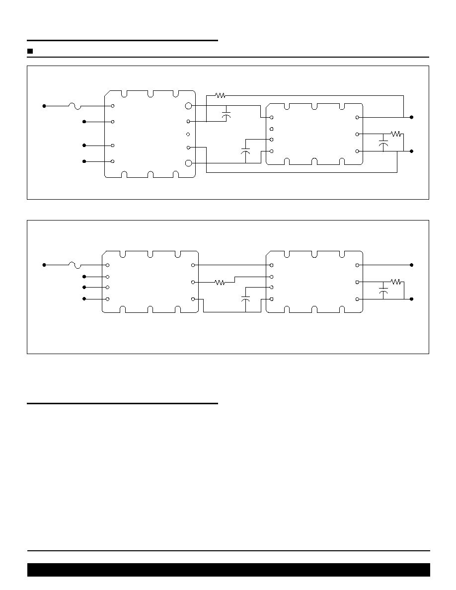
APPLICATION SCHEMATIC DRAWINGS USING VICOR CONVERTERS AND THE µRAM
DC-DC
Converter
µ
RAM
+Out
V
REF
≠Out
+In
SC
C
TRAN
≠In
+Out
+S
SC
≠S
≠Out
+In
PC
PR
≠In
(2)
R
SENSE
5.1
22
µ
F
C
TRAN
*
*
Optional Component
R
HR
C
HR
*
Figure 1--Typical Configuration using Remote Sensing
DC-DC
Converter
+Out
SC
≠Out
+In
PC
PR
≠In
µ
RAM
+Out
V
REF
≠Out
+In
SC
C
TRAN
≠In
R
SC
R
HR
C
TRAN
*
C
HR
*
*
Optional Component
Figure 2--Typical Configuration using SC Control (Oppional C
HR
25µF maximum in SC configuration.)
Functional Description
The MicroRAM has an internal passive filter that
effectively attenuates ripple in the 50kHz to 1MHz range.
An active filter provides attenuation from low frequency
up to the 1MHz range. The user must set the headroom
voltage of the active block with the external R
HR
resistor
to optimize performance. The MicroRAM must be connected
as shown in Figures 1 or 2 depending on the load sensing
method. The transient load current performance can be
increased by the addition of optional C
TRAN
capacitance
to the C
TRAN
pin. The low frequency ripple attenuation
can be increased by addition of optional C
HR
capacitance
to the V
REF
pin as shown in Figures 3a and 3b, on p. 5.
Transient load current is supplied by the internal C
TRAN
capacitance, plus optional external capacitance, during the
time it takes the converter loop to respond to the increase
in load. The MicroRAM's active loop responds in roughly
one microsecond to output voltage perturbations. There
are limitations to the magnitude and the rate of change of
the transient current that the MicroRAM can sustain while
the converter responds. See Figures 8-16, on pp. 6 and 7,
for examples of dynamic performance. A larger headroom
voltage setting will provide increased transient performance,
ripple attenuation and power dissipation while reducing
overall efficiency (see Figures 4a, 4b, 4c and 4d on p. 5).
Vicor Corp. Tel: 800-735-6200, 978-470-2900 Fax: 978-475-6715
MicroRAM Data Sheet
Rev. 1.1
Page 4 of 8
Set your site on VICOR at www.vicorpower.com
PRELIMINARY
Functional Description (continued)
The active loop senses the output current and reduces the
headroom voltage in a linear fashion to approximate
constant power dissipation of MicroRAM with increasing
loads (see Figures 5, 6 & 7, p. 6). The headroom setting
can be reduced to decrease power dissipation where the
transient requirement is low and efficient ripple
attenuation is the primary performance concern.
The active dynamic headroom range is limited on the low
end by the initial headroom setting and the maximum
expected load. If the maximum load in the application is
10 Amps, for example, the 1 Amp headroom can be set
75mV lower to conserve power and still have active
headroom at the maximum load current of 10 Amps. The
high end or maximum headroom range is limited by the
internal OR'ing diode function.
The SC or trim-up function can be used when remote
sensing is not available on the source converter or is not
desirable. It is specifically designed for converters with a
1.23 Volt reference and a 1k ohm input impedance like
Vicor 2nd Generation converters. In comparison to remote
sensing, the SC configuration will have an error in the load
voltage versus load current. It will be proportional to the
output current and the resistance of the load path from the
output of the MicroRAM to the load.
The OR'ing feature prevents current flowing from the
output of the MicroRAM back through it's input terminal
in a redundant system configuration in the event that a
converter output fails. When the converter output
supplying the MicroRAM droops below the OR'ed output
voltage potential of the redundant system, the input of the
MicroRAM is isolated from it's output. Less than 50mA
will flow out of the input terminal of the MicroRAM over
the full range of input voltage under this condition.
Application Notes
Load capacitance can affect the overall phase margin of
the MicroRAM active loop as well as the phase margin of
the converter loop. The distributed variables such as
inductance of the load path, the capacitor type and value as
well as its ESR and ESL also affect transient capability at
the load. The following guidelines should be considered
when point of load capacitance is used with the MicroRAM
in order to maintain a minimum of 30 degrees of phase margin.
1) Using ceramic load capacitance with <1milliohm
ESR and <1nH ESL:
(a) 20µF to 200µF requires 20nH of trace/wire
load path inductance
(b) 200µF to 1,000µF requires 60nH of trace/wire
load path inductance
2) For the case where load capacitance is connected
directly to the output of the MicroRAM, i.e. no
trace inductance, and the ESR is >1 milliohm:
(a) 20µF to 200µF load capacitance needs an ESL
of >50nH
(b) 200µF to 1,000µF load capacitance needs an
ESL of >5nH
3) Adding low ESR capacitance directly at the output
terminals of MicroRAM is not recommended and
may cause stability problems.
4) In practice the distributed board or wire inductance at a
load or on a load board will be sufficient to isolate the
output of the MicroRAM from any load capacitance
and minimize any appreciable effect on phase margin.
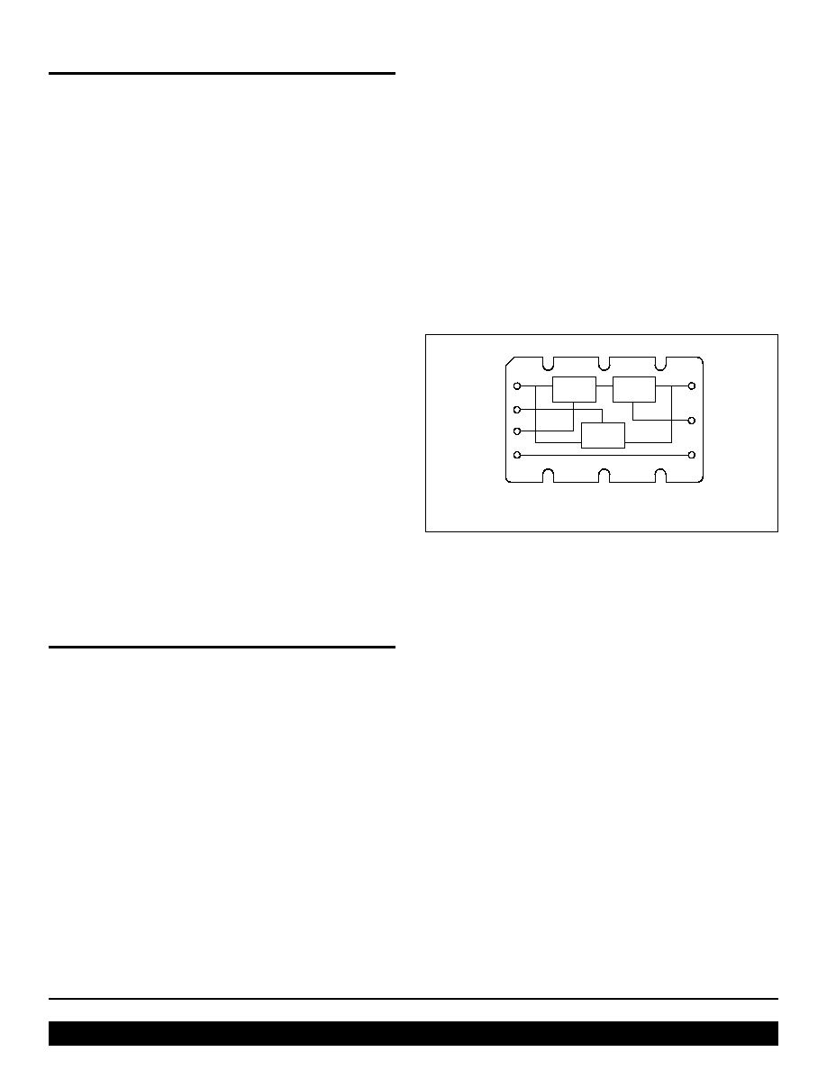
µ
RAM Block Diagram
+Out
V
REF
≠Out
+In
SC
C
TRAN
≠In
Passive
Block
Active
Block
SC
Control

Set your site on VICOR at www.vicorpower.com
PRELIMINARY
Vicor Corp. Tel: 800-735-6200, 978-470-2900 Fax: 978-475-6715
MicroRAM
Rev. 1.1
Page 5 of 8
µRAM2xxx
Ripple Attenuation @ 28V (Room Temp.)
-80.00
-60.00
-40.00
-20.00
0.00
20.00
10
100
1,000
10,000
100,000
1,000,000
10,000,000
Freq. (Hz)
Gain (dB)
10A, 100uF Vref
10A, No Vref Cap
Ripple Attenuation @ 5V (Room Temp.)
-80.00
-60.00
-40.00
-20.00
0.00
20.00
10
100
1,000
10,000
100,000
1,000,000
10,000,000
Freq. (Hz)
Gain (dB)
10A, 100uF Vref
10A, No Vref Cap
Figure 3a, 3b--Curves demonstrating the small signal attenuation performance as measured on a network analyzer with a typical
module at (a) 28V and 10A output and (b) 5V and 10A. The low frequency attenuation can be enhanced by connecting a 100µF
capacitor, C
HR
, to the V
REF
pin as shown in Figures 1 and 2.
Figure 4a-4b--Simulated graphs demonstrating the tradeoff of attenuation versus headroom setting at 20 Amps and an equivalent
100∞C baseplate temperature at 3V and 28V.
Figure 4c-4d--MicroRam attenuation vs. power dissipation at 3V 20A, and 28V 20A.
Frequency
10Hz
100Hz
1.0KHz
10KHz
100KHz
1.0MHz
...
DB(V(VOUT))
-75
-50
-25
-0
Vout=3V Iload=20A
100 degrees baseplate temperature
Rhr=28k (Vheadroom=90mV)
27k (100mV)
22k (160mV)
23k (150mV)
24k (135mV)
25k (122mV)
26k (110mV)
17k (260mV)
18k (240mV)
19k (217mV)
20k (197mV)
21k (180mV)
Frequency
10Hz
100Hz
1.0KHz
10KHz
100KHz
1.0MHz
...
DB(V(VOUT))
-75
-50
-25
-0
Rhr=260k (Vheadroom=90mV)
250k (100mV)
240k (110mV)
230k (122mV)
220k (135mV)
210k (150mV)
200k (160mV)
190k (180mV)
180k (197mV)
170k (217mV)
160k (240mV)
150k (260mV)
Vout=28V Iload=20A
100 degrees baseplate temperature
17k
18k
19k
20k
21k
22k
23k
24k
25k
26k
27k
Rhr=28k
-70
-60
-50
-40
-30
-20
-10
3.0
3.5
4.0
4.5
5.0
5.5
6.0
Watts
500khz 3V
1Mhz 3V
100khz 3V
dB
28V 20A
Rhr=260k
250k
240k
230k
220k
210k
200k
190k
180k
170k
160k
150k
-70
-60
-50
-40
-30
-20
-10
3.0
3.5
4.0
4.5
5.0
5.5
6.0
Watts
dB
100khz 28V
500khz 28V
1Mhz 28V
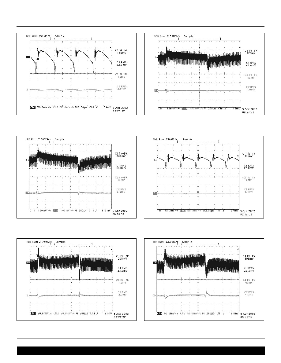
Notes:The measurements in Figures 8-16 were taken with a µRAM2C21 and standard scope probes with a 20MHz bandwidth scope setting. The criteria for transient current
capability was as follows: The transient load current step was incremented from 10A to the peak value indicated, then stepped back to 10A until the resulting output peak to
peak was around 40mV.

Vicor Corp. Tel: 800-735-6200, 978-470-2900 Fax: 978-475-6715
MicroRAM Data Sheet
Rev. 1.1
Page 6 of 8
Set your site on VICOR at www.vicorpower.com
PRELIMINARY
Figure 7--Headroom vs. load current at 28V output.
Figure 8--V375A28C600A and µRAM; Input and output ripple
@50% (10A) load CH1=Vi; CH2=Vo; Vi-Vo=332mV; RHR=178k
µRAM2xxx (
µRAM3xxx data not included in this rev.)
Figure 9--V375A28C600A and µRAM; Input and output
dynamic response no added C
TRAN
; 20% of 20A rating load
step of 4A (10A14A);R
HR
=178k (Configured as in Figs. 1 & 2)
Figure 10--V375A28C600A and µRAM; Input and output
dynamic response C
TRAN
=820µF Electrolytic; 32.5% of load step
of 6.5A (10A16.5A);R
HR
=178k (Configured as in Figs. 1 & 2)
I_Iload
2 A
4 A
6 A
8 A
1 0 A
1 2 A
1 4 A
1 6 A
1 8 A
2 0 A
1 A
V(VSOURCE) ≠V(VOut)
200mV
300mV
400mV
450mV
VOUT=28V
1 9 0 k
Rhr=150k
1 6 0 k
1 7 0 k
1 8 0 k
2 0 0 k
Vheadroom
Figure 5--Headroom vs. load current at 3V output.
Figure 6--Headroom vs. load current at 15V output.
I_Iload
2 A
4 A
6 A
8 A
1 0 A
1 2 A
1 4 A
1 6 A
1 8 A
2 0 A
1 A
V(VSOURCE) ≠V(VOut)
200mV
300mV
400mV
450mV
VOUT=3V
2 0 k
Rhr=16k
1 7 k
1 8 k
1 9 k
2 1 k
Vheadroom
I_Iload
2 A
4 A
6 A
8 A
1 0 A
1 2 A
1 4 A
1 6 A
1 8 A
2 0 A
1 A
V(VSOURCE) ≠V(VOut)
200mV
300mV
400mV
450mV
VOUT=15V
1 0 0 k
Rhr=80k
8 5 k
9 0 k
9 5 k
1 0 5 k
Vheadroom
Set your site on VICOR at www.vicorpower.com
PRELIMINARY
Vicor Corp. Tel: 800-735-6200, 978-470-2900 Fax: 978-475-6715
MicroRAM
Rev. 1.1
Page 7 of 8
Figure 12--V300B12C250A and µRAM; Input and output
dynamic response no added C
TRAN
; 17.5% of 20A rating load
step of 3.5A (10A13.5A);R
HR
=80k (Configured as in Figs. 1 & 2)
Figure 11--V375B12C250A and µRAM; Input and output ripple
@50% (10A) load CH1=Vi; CH2=Vo; Vi-Vo=305mV; R
HR
=80k
(Configured as in Figs. 1 & 2)
Figure 13--V300B12C250A and µRAM; Input and output
dynamic response C
TRAN
=820µF Electrolytic; 30% of load
step of 6A (10A16A);R
HR
=80k (Configured as in Figs. 1 & 2)
Figure 14--V48C5C100A and µRAM; Input and output ripple
@50% (10A) load CH1=Vi; CH2=Vo; Vi-Vo=327mV; R
HR
=31k
(Configured as in Figs. 1 & 2)
µRAM2xxx
Figure 15--V48C5C100A and µRAM; Input and output dynamic
response no added C
TRAN
; 22.5% of 20A rating load step of 4.5A
(10A14.5A);R
HR
=31k (Configured as in Figs. 1 & 2)
Figure 16--V48C5C100A and µRAM; Input and output dynamic
response C
TRAN
=820µF Electrolytic; 35% of load step of 7A
(10A17A);R
HR
=31k (Configured as in Figs. 1 & 2)
Vicor Corp. Tel: 800-735-6200, 978-470-2900 Fax: 978-475-6715
MicroRAM Data Sheet
P/N 25774
Rev.1.1
11/02/10M
Set your site on VICOR at www.vicorpower.com
PRELIMINARY
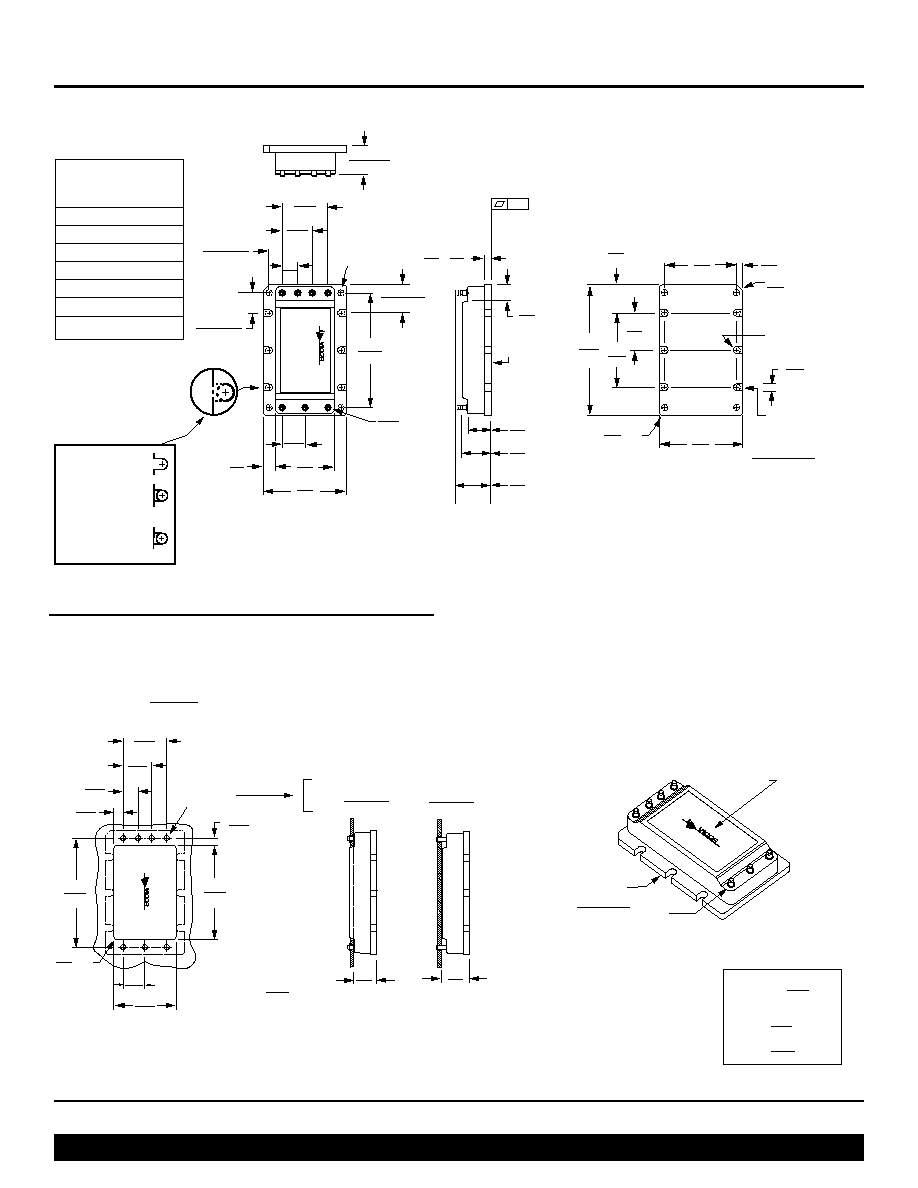
Mechanical Drawings
PCB MOUNTING SPECIFICATIONS
5
6
7
4
3
2
1
(REF)
0.080
2,03
DIA. (7X)
0.21
5,2
0.27
6,9
(2X)
1.04
26,4
1.45
36,8
.275
6,99
0.800
20,32
0.525
13,34
0.400
10,16
0.12*
3,1
0.20**
5,08
0.01
0.54
13,7
0.43
10,9
Pin Style 2&N
(Long Pin)
0.62
15,7
Pin Style 1&S
(Short Pin)
(7X)
(7X)
Slotted (Style 1)
or
Threaded (Style 2)
4-40 UNC-2B (6X)
or
Thru Hole (Style 3)
#30 Drill Thru (6X)
(0.1285)
(ALL MARKINGS
THIS SURF
A
CE)
ALUMINUM
BASEPLATE
12,7
±
0,5
0.50
±
0.02
* Style 1 baseplate only
** Style 2 & 3 baseplates
*** Reserved for Vicor accessories
Not for mounting
style 2 & 3
baseplates only
(4X)***
0.490
±
.015
12,45
±
0,38
(REF)
IN
OUT
uRAM
2.000
50,80
0.235
±
.015
5,97
±
0,38
(REF)
0.350
±
.015
8,89
±
0,38
(REF)
FULL R (6X)
0.10
2,5
CHAMFER
(REF.)
(6X)
0.65
16,5
0.49
12,4
1.30
33,0
2.28
57,9
1.45
36,8
0.13
3,3
0.06
1,5
R
(3X)
X 45∞
Use a
4-40 Screw (6x)
Torque to:
5 in-lbs
0.57 N-m
1.27
32,3
0.09
2,3
2
3
6
1
7
4
5
PLATED
THRU HOLE
DIA
±
0,08
*DENOTES TOL =
±
0.003
0.133
3,38
1.734**
44,04
.400*
10,16
1.140**
28,96
0.170*
4,32
0.800*
20,32
0.525*
13,34
0.275*
6,99
2.000*
50,80
0.06
1,5
R
(4X)
INBOARD
SOLDER
MOUNT
PIN STYLE 1&S
0.094
±
0.003
2,39
±
0,08
0.43
10,9
(7X)
**PCB WINDOW
PCB THICKNESS
0.062
±
0.010
1,57
±
0,25
0.53
13,5
ONBOARD
SOLDER
MOUNT
PIN STYLE 2&N
0.094
±
0.003
2,39
±
0,08
PINS STYLES
STYLE 1 & 2: TIN/LEAD
HOT SOLDER DIPPED
STYLE S & N: GOLD PLATED COPPER
ALUMINUM
BASEPLATE
ALL MARKINGS
THIS SURFACE
MODULE OUTLINE
Unless otherwise specified,
dimensions are in inches
mm
Decimals
Tol.
Angles
0.XX
±0.01
±0,25
±1∞
0.XXX
±0.005
±0,127
uRAM Pins
No.
Function
Label
1
+In
+
2
Control
SC
3
C ext.
CTRAN
4
≠In
≠
5
≠Out
≠
6
Reference
Vref
7
+Out
+