Set your site on VICOR at www.vicorpower.com
Vicor Corp. Tel: 800-735-6200, 978-470-2900 Fax: 978-475-6715
V24A24C400B DC-DC Converter
Rev. 3
Page 1 of 8
Parameter
Rating
Unit
Notes
+In to ≠In voltage
-0.5 to +36
Vdc
+In to ≠In voltage
50
Vdc
<100ms
PC to ≠In voltage
-0.5 to +7.0
Vdc
PR to ≠In voltage
-0.5 to +7.0
Vdc
+Out to ≠Out voltage
-0.5 to +31.7
Vdc
+Sense to ≠Out voltage
-0.5 to +31.7
Vdc
≠Sense to ≠Out voltage
1.0
Vdc
SC to ≠Out voltage
-0.5 to +1.5
Vdc
Isolation voltage (in to out)
2000
Vrms
Isolation voltage (in to base)
1550
Vrms
Isolation voltage (out to base)
500
Vrms
Storage temperature (C≠ Grade)
-40 to +125
∞C
Operating temperature (C≠ Grade)
-20 to +100
∞C
Baseplate
Pin soldering temperature
500 (260)
∞F (∞C)
<5 sec; wave solder
Pin soldering temperature
750 (390)
∞F (∞C)
<7 sec; hand solder
Mounting torque
5 (0.57)
in-lbs (N-m)
6 each, # 4-40 or M3
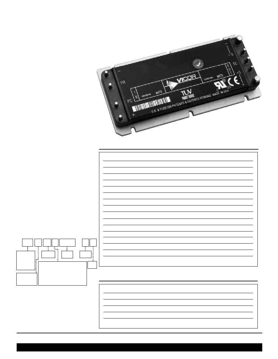
Shown actual size:
4.6 x 2.2 x 0.5 in
117 x 56 x 12,7 mm
4
5
Absolute Maximum Ratings
Parameter
Min
Typ
Max
Unit
Baseplate to sink; flat, greased surface
0.08
∞C/Watt
Baseplate to sink; thermal pad (P/N 20263)
0.07
∞C/Watt
Baseplate to ambient
4.9
∞C/Watt
Baseplate to ambient; 1000 LFM
1.1
∞C/Watt
Thermal capacity
165
Watt-sec/∞C
Thermal Resistance and Capacity
24Vin / 24Vout / 400Watts
DC-DC Converter Module
Model Number V24A24C400B*
Features
∑
DC input range: 18 - 36V
∑
Input surge withstand: 50V for 100ms
∑
DC output: 24V
∑
Programmable output: 10 to 110%
∑
Regulation: ±0.2% no load to full load
∑
Efficiency: 87%
∑
Maximum operating temperature:
100∞C at full load
∑
Power density: 79W/cubic inch
∑
Height above board: 0.43 in. (10,9 mm)
∑
Parallelable, with N+M fault tolerance
∑
Low noise ZCS/ZVS architecture
Typical Applications: telecommunications,
process control and distributed power
systems
Product Overview
This DC-DC converter module uses
2nd Generation power processing, control
and packaging technologies to provide the
performance, flexibility and cost effectiveness
expected of a mature power component.
For example, a plated-cavity core transformer
couples widely separated primary and
secondary windings, resulting in low in-to-
out parasitic capacitance and noise.
High frequency ZCS/ZVS switching,
advanced power semiconductor packaging
and thermal management provide high
power density with low temperature
gradients. Extensive use of silicon
integration results in 1/3 the part count
of a 1st Generation converter.
* Part Numbering
For pin styles see page 6. Slotted baseplate
(style 1) requires no designator. For
threaded baseplate add a "2" to the end of
the part number. For thru-hole, add a "3".
See page 7 for dimensions.
See part numbering chart on this
page for other product grades.
V 24 A 12 C 500 B
Input Voltage
24 = 24Vin
48 = 48Vin
300 = 300Vin
375 = 375Vin
A = Maxi
B = Mini
C = Micro
Output
Voltage
Product Grade Temperatures (∞C)
Grade
Storage
Operating
C = - 40 to +125 - 20 to +100
T = - 40 to +125 - 40 to +100
H = - 55 to +125 - 40 to +100
M = - 65 to +125 - 55 to +100
Pin
Style
Base-
plate
Output
Power
Vicor Corp. Tel: 800-735-6200, 978-470-2900 Fax: 978-475-6715
V24A24C400B DC-DC Converter
Rev. 3
Page 2 of 8
Set your site on VICOR at www.vicorpower.com
Parameter
Min
Typ
Max
Unit
Notes
Operating input voltage
18
24
36
Vdc
Input surge withstand
50
Vdc
<100ms
Output voltage setpoint
23.76
24
24.24
Vdc
Nominal input; full load; 25∞C
Output OVP setpoint
27.1
28.1
29.1
Vdc
25∞C; recycle input voltage to restart ( 1 minute off )
Output power
400
Watts
At 100∞C baseplate temperature
Efficiency
85.5
87
%
Nominal input; 75% of full load; 25∞C
Parameter
Min
Typ
Max
Unit
Notes
Line regulation
±0.02
±0.2
%
Low line to high line; full load
Load regulation
±0.06
±0.2
%
No load to full load; nominal input
Temperature regulation
±0.002
±0.005
% / ∞C
Over operating temperature range
Ripple and noise, p-p
80
100
mV
Nominal input, full load; 25∞C; 20MHz bandwidth
Current limit
17
19.2
21.7
Amps
Output voltage 95% of nominal
Short circuit current
2.25
19.2
21.7
Amps
Output voltage <250mV
Power sharing accuracy
±2
±5
%
10 to 100% of full load
Programming range
10
110
%
Of nominal output voltage. For trimming below
90% of nominal, a minimum load of 10% of
maximum rated power may be required.
Parameter
Min
Typ
Max
Unit
Notes
Undervoltage turn-on
17.5
17.9
Vdc
Undervoltage turn-off
14.77
15.3
Vdc
Overvoltage turn-off/on
36.3
37.8
39.6
Vdc
Dissipation, standby
9.3
14
Watts
No load
MODULE OPERATING SPECIFICATIONS
MODULE INPUT SPECIFICATIONS
MODULE OUTPUT SPECIFICATIONS
ELECTRICAL CHARACTERISTICS
Electrical characteristics apply over the full operating range of input voltage, output load (resistive) and baseplate temperature,
unless otherwise specified. All temperatures refer to the operating temperature at the center of the baseplate.
Baseplate
Slotted (Style 1)
Slotted baseplate (style 1) requires no designator.
For threaded baseplate add a "2" to the end of the
part number. For thru-hole add a "3".
Pin style
Short (Style 1)
For long pin configuration add "L" to the end of the
part number. See page 7 for pin dimensions.
MODULE MECHANICAL SPECIFICATIONS
Note: For important information relative to applications where the converter modules are subject to continuous dynamic loading,
contact Vicor applications engineering at 800-927-9474.
Set your site on VICOR at www.vicorpower.com
Vicor Corp. Tel: 800-735-6200, 978-470-2900 Fax: 978-475-6715
V24A24C400B DC-DC Converter
Rev. 3
Page 3 of 8
Parameter
Min
Typ
Max
Unit
Notes
PRIMARY SIDE
(PC = Primary Control; PR = Parallel)
PC bias voltage
5.50
5.75
6.10
Vdc
PC current = 1.0 mA
current limit
1.5
2.1
3.0
mA
PC voltage = 5.5V
PC module disable
2.3
2.3
2.6
Vdc
Must be able to sink
4 mA. See Fig. 1
PC module enable delay
4
7
ms
PC module alarm
0.5
Vavg
UV, OV, OT, module fault. See Figs. 2 and 4
PR emitter amplitude
5.7
5.9
6.1
Volts
PR load >30 ohms, < 30 pF
PR emitter current
150
mA
PR receiver impedance
375
500
625
ohms
25∞C
PR receiver threshold
2.4
2.5
2.6
Volts
Minimum pulse width: 20ns
PR drive capability
12
modules
Without PR buffer amplifier
SECONDARY SIDE
(SC = Secondary Control)
SC bandgap voltage
1.21
1.23
1.25
Vdc
Referenced to ≠Sense
SC resistance
990
1000
1010
ohms
SC capacitance
0.033
µF
SC module alarm
0
Vdc
With open trim; referenced to ≠Sense. See Fig. 6
Parameter
Min
Typ
Max
Unit
Notes
Remote sense (total drop)
0.5
Vdc
0.25V per leg (senses must be closed)
Isolation voltage (in to out)
2000
Vrms
Complies with reinforced insulation requirements
Isolation voltage (in to base)
1550
Vrms
Complies with basic insulation requirements
Isolation voltage (out to base)
500
Vrms
Complies with operational insulation requirements
Isolation resistance (in to out)
10
megohms
Weight
7.3 (210)
8 (227)
ounces (grams)
Temperature limiting
100
115
∞C See Figs. 2 and 4
Agency approvals
cULus, TÐV, CE
UL60950, EN60950, CSA60950, IEC 60950.
With a fuse in series with the +Input
MODULE CONTROL SPECIFICATIONS
MODULE GENERAL SPECIFICATIONS
ELECTRICAL CHARACTERISTICS, continued
Note: The cover is electrically conductive and may be electrically connected to the baseplate.
Vicor Corp. Tel: 800-735-6200, 978-470-2900 Fax: 978-475-6715
V24A24C400B DC-DC Converter
Rev. 3
Page 4 of 8
Set your site on VICOR at www.vicorpower.com
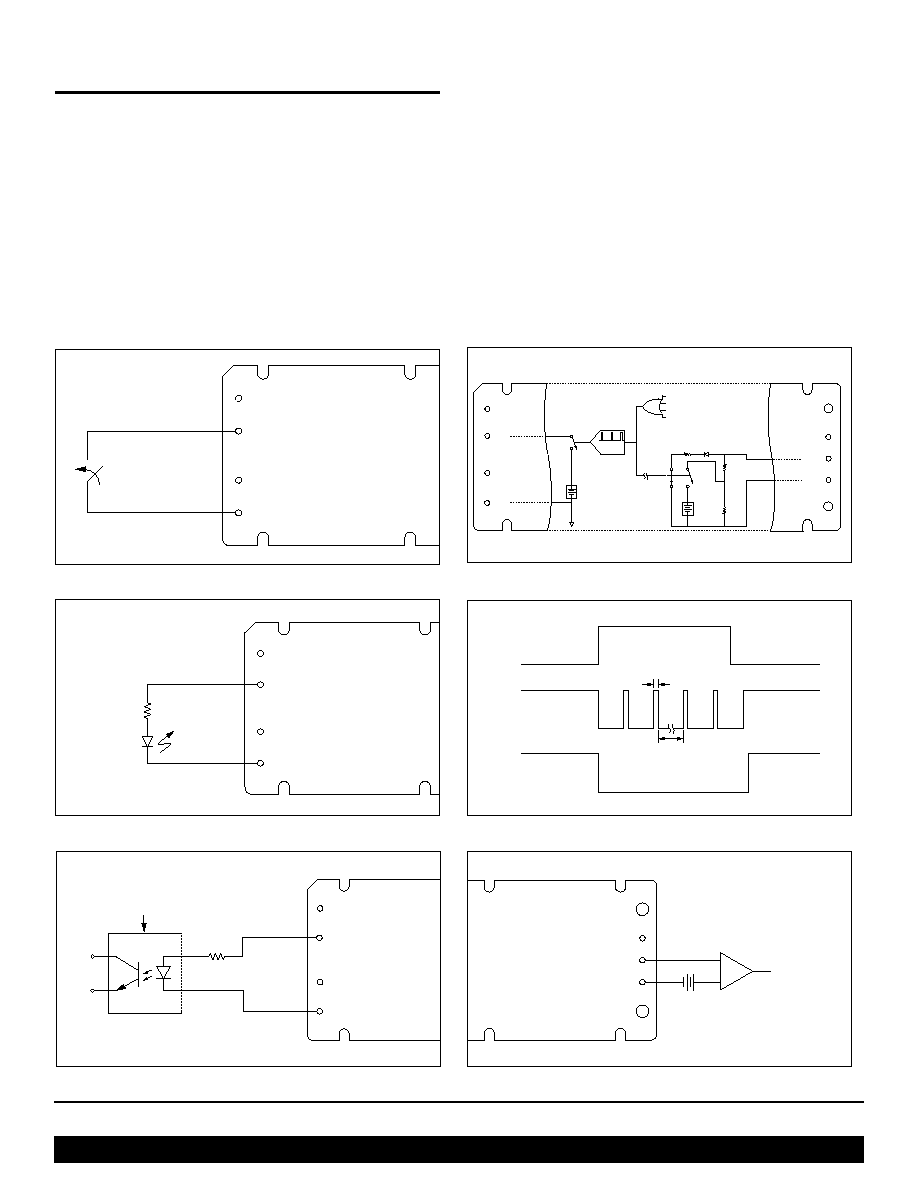
CONTROL FUNCTIONS - PC PIN
Module Enable/Disable
The module may be disabled by pulling PC below 2.3V with
respect to the ≠Input. This may be done with an open collector
transistor, relay, or optocoupler. Multiple converters may be
disabled with a single transistor or relay either directly or via
"OR'ing" diodes. See Figure 1.
Module Alarm
The module contains "watchdog" circuitry which monitors
input voltage, operating temperature and internal operating
parameters. In the event that any of these parameters are
outside of their allowable operating range, the module will shut
down and PC will go low. PC will periodically go high and the
module will check to see if the fault (as an example,
overtemperature) has cleared. If the fault has not been cleared,
PC will go low again and the cycle will restart. The SC pin will
go low in the event of a fault and return to its normal state after
the fault has been cleared. See Figures 2 and 4.
+In
PC
PR
≠In
Disable
Disable = PC <2.3V
Figure 1--Module enable/disable.
Figure 3--LED on-state indicator.
+In
PC
PR
≠In
4k
"Module
Enabled"
+In
PC
PR
≠In
Optocoupler
4k
Alarm
1.00V
+Out
+S
SC
≠S
≠Out
+Out
+S
SC
≠S
≠Out
+In
PC
PR
≠In
Input Undervoltage
2-20ms typ.
f (VIN)
Auto
Restart
5.7Vdc
(0-3mA)
50
SW2
SW3
1.23
Vdc
6K
1K
SW1
SW1, 2, & 3
shown in
"Fault" position
Input Overvoltage
Overtemperature
Module Faults
Figure 2--PC/SC module alarm logic.
Figure 5--Isolated on-state indicator.
2-20ms typ.
Fault
SC
PC
1.23V
5.7V
40
µ
s typ.
Figure 4--PC/SC module alarm timing.
Figure 6--Secondary side on-state indicator.
Primary Auxiliary Supply
At 5.7V, PC can source up to 1.5mA. In the example shown in
Figure 3, PC powers a module enabled LED.
Set your site on VICOR at www.vicorpower.com
Vicor Corp. Tel: 800-735-6200, 978-470-2900 Fax: 978-475-6715
V24A24C400B DC-DC Converter
Rev. 3
Page 5 of 8
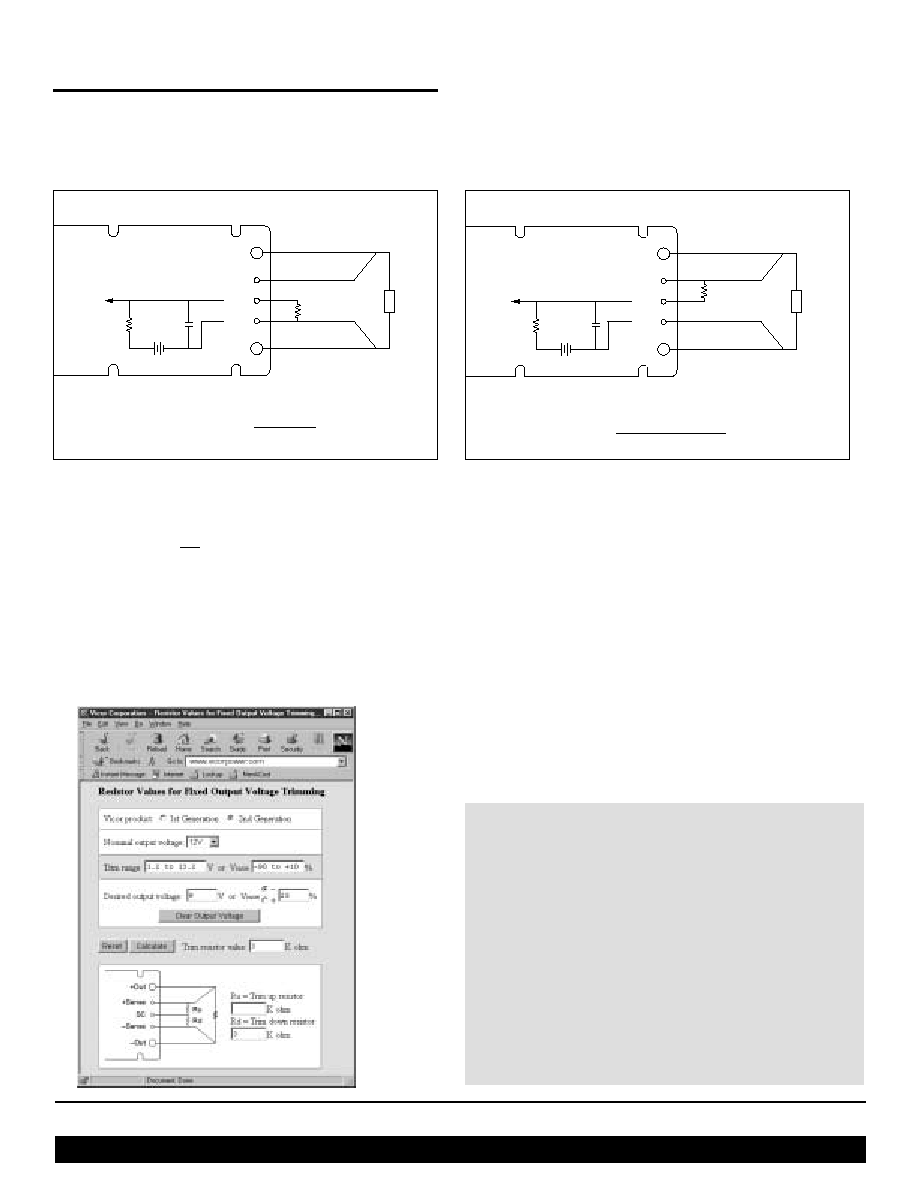
Output Voltage Programming
The output voltage of the converter can be adjusted or
programmed via fixed resistors, potentiometers or voltage
DACs. See Figures 7 and 8.
CONTROL FUNCTIONS - SC PIN
Figure 8--Output voltage trim up circuit.
Figure 7--Output voltage trim down circuit.
R
D
(ohms) =
1,000 Vout
Vnom - Vout
+Out
+S
SC
≠S
≠Out
R
U
Trim Up
Load
Error
Amp
1k
1.23V
0.033
µ
F
Load
+Out
+S
SC
≠S
≠Out
R
D
Trim Down
Error
Amp
1k
1.23V
0.033
µ
F
Trim Down
1. This converter is not a constant power device ≠ it has a
constant current limit. Hence, available output power is
reduced by the same percentage that output voltage is
trimmed down. Do not exceed maximum rated output current.
2. The trim down resistor must be connected to the ≠Sense pin.
Trim Up
1. The converter is rated for a maximum delivered power. To ensure
that maximum rated power is not exceeded, reduce maximum
output current by the same percentage increase in output voltage.
2. The trim up resistor must be connected to the +Sense pin.
3. Do not trim the converter above maximum trim range
(typically +10%) or the output over voltage
protection circuitry may be activated.
Trim resistor values calculated automatically:
On-line calculators for trim resistor values are available
on the vicor website at: vicorpower.com/tools.html.
Resistor values can be calculated for fixed trim up, fixed
trim down and for variable trim up or down cases for both
1st and 2nd Generation DC-DC converters.
In addition to trimming information, the web site and the
Applications Manual also include design tips, applications
circuits, EMC suggestions, thermal design guidelines and
PDF data sheets for all available Vicor products.
R
U
(ohms) =
1,000 (Vout-1.23) Vnom
≠1,000
1.23 (Vout-Vnom)