 | –≠–ª–µ–∫—Ç—Ä–æ–Ω–Ω—ã–π –∫–æ–º–ø–æ–Ω–µ–Ω—Ç: 196DLC | –°–∫–∞—á–∞—Ç—å:  PDF PDF  ZIP ZIP |
196 DLC
Vishay BCcomponents
Document Number: 28362
For technical questions contact: aluminumcaps1@vishay.com
www.vishay.com
Revision: 17-Oct-03
193
Double Layer Capacitors
FEATURES
∑ Polarized capacitor with high charge density,
alternative product to rechargeable backup batteries
∑ Dielectric: electric double layer
∑ Radial leads, cylindrical case,
insulated with a blue vinyl sleeve
∑ Available in both vertical and low-profile versions
∑ Unlimited charge and discharge cycle numbers
∑ No charge-discharge control circuitry
and no series resistor necessary
∑ Maintenance-free, no periodic replacement
or service necessary
∑ Ecologically beneficial (no Cd, no Li).
APPLICATIONS
∑ Energy storage, for backup of semiconductor memories
(CMOS) in all fields of electronics
∑ Telecommunication, audio-video, EDP
∑ General industrial, clock and timer systems.
MARKING
The capacitors are marked with the following information:
∑ Rated capacitance (in F).
∑ Rated voltage (in V).
∑ Date code, in accordance with IEC 60062.
∑ Name of manufacturer.
∑ Negative terminal identification.
∑ Upper category temperature (at 85 ∞C types only).
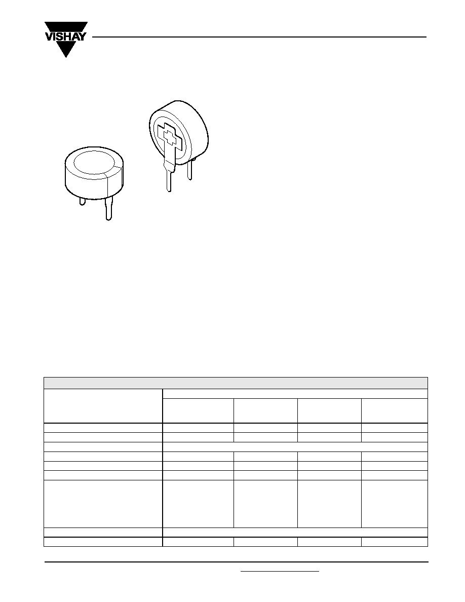
Form A
Form B
Fig.1 Component outline.
QUICK REFERENCE DATA
DESCRIPTION
VALUE
STANDARD
FORM A
HIGH VOLTAGE
FORM A
HIGH
TEMPERATURE
FORM A
VERTICAL,
MINIATURIZED
FORM B
Nominal case sizes (
D ◊ L in mm)
13 x 7 and 21 x 7.5
13 x 9 and 21 x 9
13 x 9 and 21 x 9
11.5 x 13 (vertical)
Rated capacitance range, C
R
0.047 to 1.0 F
0.047 to 0.68 F
0.047 to 0.68 F
0.047 to 0.33 F
Tolerance on C
R
at 20
∞C
-20 to +80%
Rated voltage, U
R
5.5 V
6.3 V
5.5 V
5.5 V
Maximum surge voltage, U
S
6.3 V
7.0 V
6.3 V
6.3 V
Category temperature range
-25 to +70 ∞C
-25 to +70 ∞C
-25 to +85 ∞C
-25 to +70 ∞C
Useful life at U
R
:
at 85
∞C
-
-
1000 hours
-
at 70
∞C
1 000 hours
1 000 hours
2800 hours
1 000 hours
at 40
∞C
8 000 hours
8 000 hours
23 000 hours
8 000 hours
at 25
∞C
23000 hours
23 000 hours
64 000 hours
23000 hours
Shelf life at 0 V
1 000 hours at upper category temperature
Climatic category IEC 60 068
25/070/21
25/070/21
25/085/21
25/070/21
www.vishay.com
For technical questions contact: aluminumcaps1@vishay.com
Document Number: 28362
194
Revision: 17-Oct-03
196 DLC
Vishay BCcomponents
Double Layer Capacitors
SELECTION CHART FOR C
R
, U
R
AND FORM AT UPPER CATEGORY TEMPERATURE (UCT)
C
R
(F)
FORM
U
R
= 5.5 V
U
R
= 6.3 V
UCT = 85
∞C
UCT = 70
∞C
UCT = 70
∞C
0.047
A
13
◊ 9
13
◊ 7
13
◊ 9
B
-
11.5
◊ 13
-
0.1
A
13
◊ 9
13
◊ 7
13
◊ 9
B
-
11.5
◊ 13
-
0.22
A
-
13
◊ 7
-
B
-
11.5
◊ 13
-
0.33
A
-
13
◊ 7
-
B
-
11.5
◊ 13
-
0.47
A
21
◊ 9
21
◊ 7.5
21
◊ 9
B
-
-
-
0.68
A
21
◊ 9
-
21
◊ 9
B
-
-
-
1.0
A
-
21
◊ 7.5
-
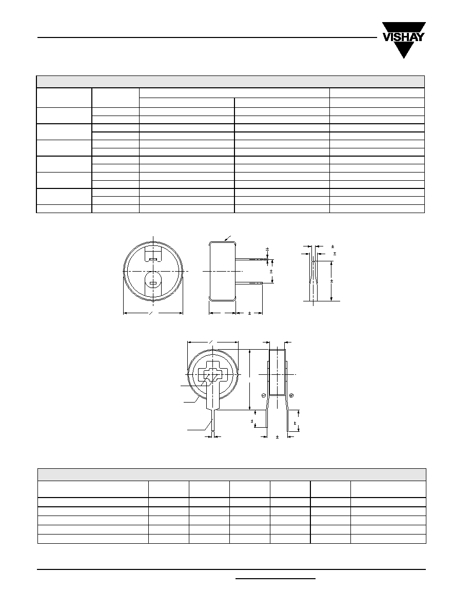
DIMENSIONS in millimeters AND AVAILABLE FORMS
Fig.2 Form A: Low profile.
O D
L
6 1
vinyl sleeve
5 0.3
0.5 0.1
0.8 0.1
1.2 0.1
6 1
D
(0.8)
L
4.0
0.3
5.0
0.3
5.0 0.5
laser weld
vinyl sleeve
solder plating
(4.5)
O
Fig.3 Form B: Vertical.
Table 1
Note
1.
Detailed tape dimensions see section `PACKAGING'.
DIMENSIONS in millimeters, MASS AND PACKAGING QUANTITIES
NOMINAL CASE SIZE
D ◊ L (mm)
CASE
CODE
FORM
D
max
L
max
MASS
(g)
PACKAGING
QUANTITIES
11.5
◊ 13
1
B
11.8
13.5
1.5
2 000
13
◊ 7
2
A
13.5
7.5
2.8
1 000
13
◊ 9
3
A
13.5
9.5
3.4
1 000
21
◊ 7.5
4
A
21.5
8.0
7.1
500
21
◊ 9
5
A
21.5
9.5
8.8
500
Document Number: 28362
For technical questions contact: aluminumcaps1@vishay.com
www.vishay.com
Revision: 17-Oct-03
195
196 DLC
Double Layer Capacitors
Vishay BCcomponents
Note
Unless otherwise specified, all electrical values in Table 2 apply at
T
amb
= 20
∞C, P = 86 to 106 kPa and RH = 45 to 75%.
ORDERING EXAMPLE
Double layer capacitor 196 series
1.0 F/5.5 V
Nominal case size:
21 ◊ 7.5 mm; Form A
Catalog number: 2222 196 12105.
ELECTRICAL DATA
SYMBOL
DESCRIPTION
C
R
rated capacitance, tolerance
-20/+80%,
measured by constant current discharge method
UCT
upper category temperature
I
L
max. leakage current after 30 minutes at U
R
R
I
max. internal resistance at 1 kHz
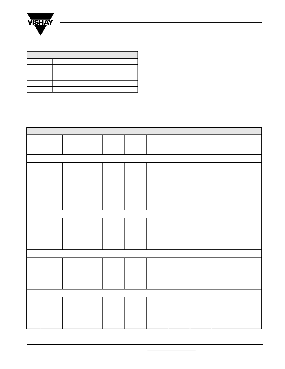
Table 2
ELECTRICAL DATA AND ORDERING INFORMATION
U
R
(V)
C
R
(F)
NOMINAL
CASE SIZE
D ◊ L
(mm)
CASE
CODE
FORM
UCT
(
∞C)
I
L
30 min.
(µA)
R
I
1 kHz(
)
CATALOG NUMBER
Standard series
5.5
0.047
13
◊ 7
2
A
70
69
120
2222 196 12473
0.1
13
◊ 7
2
A
70
100
75
2222 196 12104
0.22
13
◊ 7
2
A
70
135
75
2222 196 12224
0.33
13
◊ 7
2
A
70
182
75
2222 196 12334
0.47
21
◊ 7.5
4
A
70
216
30
2222 196 12474
1.0
21
◊ 7.5
4
A
70
315
30
2222 196 12105
High temperature series
5.5
0.047
13
◊ 9
3
A
85
69
300
2222 196 22473
0.1
13
◊ 9
3
A
85
100
200
2222 196 22104
0.47
21
◊ 9
5
A
85
216
50
2222 196 22474
0.68
21
◊ 9
5
A
85
260
50
2222 196 22684
Vertical, miniaturized series
5.5
0.047
11.5
◊ 13
1
B
70
69
120
2222 196 32473
0.1
11.5
◊ 13
1
B
70
100
75
2222 196 32104
0.22
11.5
◊ 13
1
B
70
135
75
2222 196 32224
0.33
11.5
◊ 13
1
B
70
182
75
2222 196 32334
High voltage series
6.3
0.047
13
◊ 9
3
A
70
69
300
2222 196 13473
0.1
13
◊ 9
3
A
70
100
200
2222 196 13104
0.47
21
◊ 9
5
A
70
216
50
2222 196 13474
0.68
21
◊ 9
5
A
70
260
50
2222 196 13684
www.vishay.com
For technical questions contact: aluminumcaps1@vishay.com
Document Number: 28362
196
Revision: 17-Oct-03
196 DLC
Vishay BCcomponents
Double Layer Capacitors
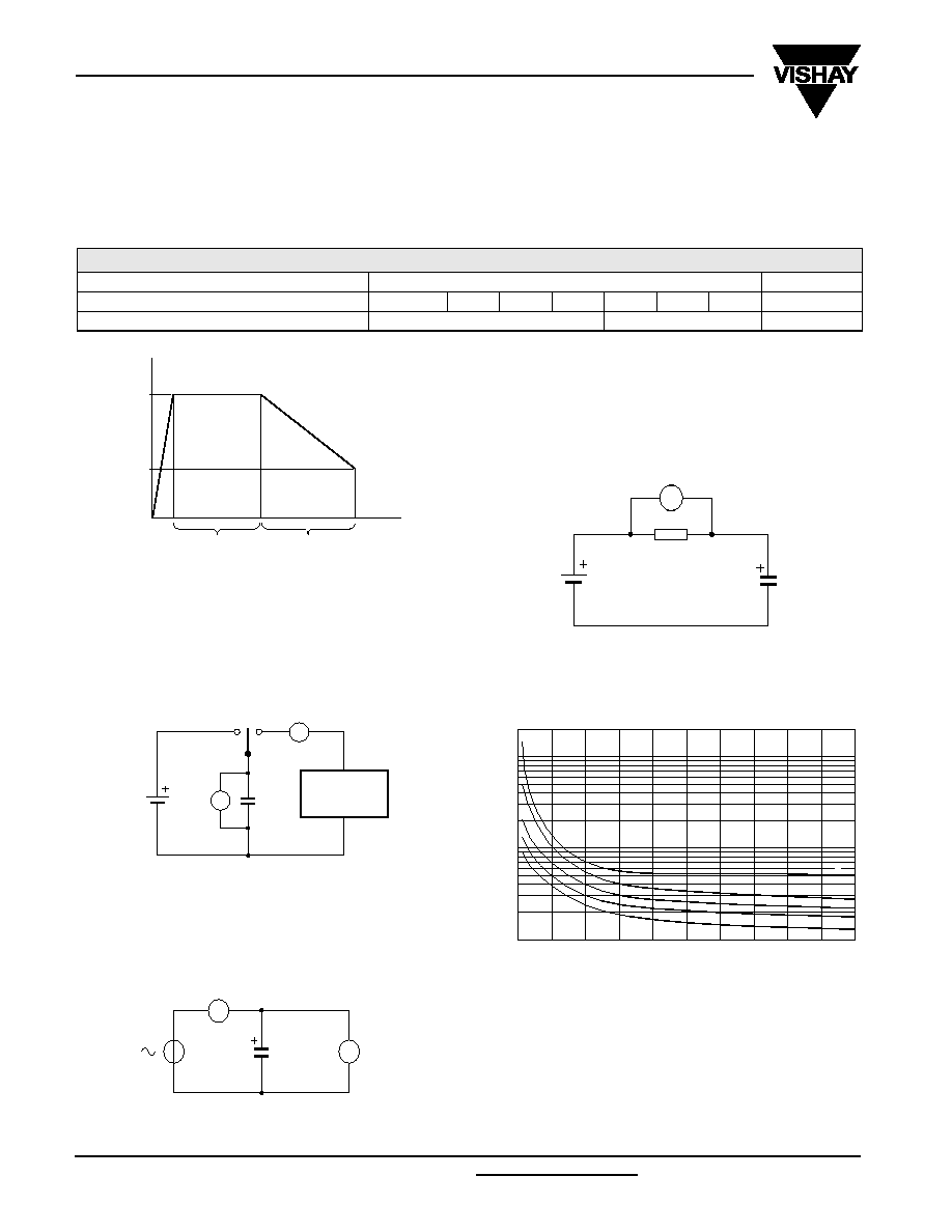
MEASURING OF CHARACTERISTICS
CAPACITANCE (C)
Capacitance shall be measured by constant current discharge method.
DISCHARGE CURRENT AS A FUNCTION OF RATED CAPACITANCE
PARAMETER
VALUE
UNIT
Rated capacitance, C
R
0.047
0.1
0.22
0.33
0.47
0.68
1.0
F
Discharge current, I
D
0.1
1.0
mA
Capacitance value C
R
is given by discharge current I
D
, time
T and rated voltage U
R
, according to the following equation:
INTERNAL RESISTANCE (R
I
) AT 1 KHz
LEAKAGE CURRENT (I
L
)
Leakage current shall be measured after 30 minutes
application of rated voltage U
R
:
Fig.4
Voltage diagram for capacitance measurement.
30 min
T (s)
time
0
2.0
U
U
(V)
R
C F
( )
I
D
mA
(
) 10
3
≠
T s
( )
◊
◊
U
R
V
( ) 2
≠
--------------------------------------------------------
=
Fig.5 Test circuit for capacitance measurement.
A
V
CONSTANT
CURRENT
DISCHARGER
C
R
I
( )
V
C
V
( )
10
3
≠
----------------
=
Fig.6 Test circuit for R
I
measurement.
V
A
1 mA
C
1 kHz
I
L
µA
(
)
V V
( )
10
4
≠
-------------
=
Fig.7 Test circuit for leakage current.
V
Rs 100
C
Fig.8 Typical leakage current as a function of time.
Curve 1: 1.0 F, 5.5 V.
Curve 2: 0.47 F, 5.5 V.
Curve 3: 0.22 F, 5.5 V.
Curve 4: 0.1 F, 5.5 V.
Curve 5: 0.047 F, 5.5 V.
R
s
= 100
.
50
1
10
20
30
40
1
10
2
10
(
µA)
I
L
time (hours)
2
3
4
5
1
Document Number: 28362
For technical questions contact: aluminumcaps1@vishay.com
www.vishay.com
Revision: 17-Oct-03
197
196 DLC
Double Layer Capacitors
Vishay BCcomponents
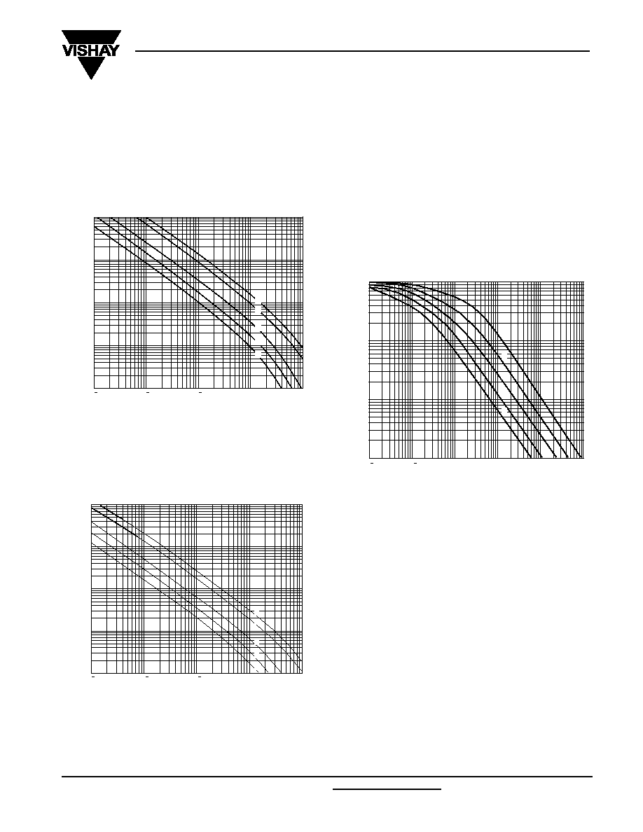
DISCHARGE CHARACTERISTICS
Backup time of 196 DLC series capacitors depends on
minimum memory holding voltage and discharge current
(corresponding with the current consumption of the load).
For minimum backup times of standard and vertical
miniaturized series see Figs 9 and 10 (charging time
24 hours).
Figure
11
shows the backup time when a 196 DLC capacitor
is discharged by a constant resistance
(charging time
24 hours).
The horizontal axis shows the initial value of discharge
current if 5 V is connected to the capacitor via a fixed series
resistor.
EXAMPLE: 1 µA CORRESPONDS TO 5 M
AND 0.1 µA
CORRESPONDS TO 50 M
The vertical axis shows that period of time during which the
voltage drops from 5 to 2 V.
Fig.9 Typical backup time as a function of discharge current.
Curve 1: 1.0 F, 5.5 V.
Curve 2: 0.47 F, 5.5 V.
Curve 3: 0.22 F, 5.5 V.
Curve 4: 0.1 F, 5.5 V.
Curve 5: 0.047 F, 5.5 V.
Voltage drop from 5.0 to 3.5 V.
10
MGA695
1
10
5
10
4
10
3
10
2
10
back up
time
(s)
discharge current (mA)
10
3
10
2
10
1
5
4
3
2
1
Fig.10 Typical backup time as a function of discharge current.
Curve 1: 1.0 F, 5.5 V.
Curve 2: 0.47 F, 5.5 V.
Curve 3: 0.22 F, 5.5 V.
Curve 4: 0.1 F, 5.5 V.
Curve 5: 0.047 F, 5.5 V.
Voltage drop from 5.0 to 2.0 V.
10
MGA696
1
10
6
10
5
10
4
10
3
10
2
back up
time
(s)
discharge current (mA)
10
3
10
2
10
1
5
4
3
2
1
10
2
10
3
10
1
10
1
10
2
MLB203
10
3
1
10
2
10
1
2
3
4
5
backup
time
(h)
initial value of discharge current (
µA)
Curve 1: 1.0 F, 5.5 V.
Curve 2: 0.47 F, 5.5 V.
Curve 3: 0.22 F, 5.5 V.
Curve 4: 0.1 F, 5.5 V.
Curve 5: 0.047 F, 5.5 V.
Voltage drop from 5.0 to 2.0 V by means of a fixed resistor..
Fig.11 Typical backup time as a function of initial
discharge current.
www.vishay.com
For technical questions contact: aluminumcaps1@vishay.com
Document Number: 28362
198
Revision: 17-Oct-03
196 DLC
Vishay BCcomponents
Double Layer Capacitors
Table 3
TEST PROCEDURES AND REQUIREMENTS for standard and vertical miniaturized series (5.5 V; 70 ∞C)
NAME OF TEST
IEC 60 384-4/
EN130 300
subclause
PROCEDURE
(quick reference)
REQUIREMENTS
Robustness of
terminations
4.4
tensile strength; application of loading force
for 10 seconds:
no breaks
20 N (standard series)
5 N (vertical miniaturized series)
Resistance to
soldering heat
4.5
solder bath; 260
∞C; 5 seconds
C/C: ±10%
R
I
and I
L
spec. limit
Solderability
4.6
solder bath; 235
∞C; 2 seconds
75% tinning
Vibration
4.8
10 to 55 Hz; 1.5 mm; 3 directions;
2 hours per direction
C/C: ±10%
R
I
and I
L
spec. limit
Damp heat, steady
state
4.12
500 hours at 55
∞C; RH 90 to 95%;
no voltage applied
C/C: ±30%
R
I
4 ◊ spec. limit
I
L
2 ◊ spec. limit
Endurance
4.13
T
amb
= 70
∞C; 5.5 V applied;
1000 hours
C/C: ±30%
R
I
4 ◊ spec. limit
I
L
2 ◊ spec. limit
Storage at upper
category temperature
4.17
T
amb
= 70
∞C;
no voltage applied;
1000 hours
C/C: ±30%
R
I
4 ◊ spec. limit
I
L
2 ◊ spec. limit
Self discharge
-
24 hours storage at room temperature after
application of 5 V for 1 hour
remaining voltage:
4 V
Characteristics at high
and low temperature
4.19
step 1: reference measurement
at +20
∞C of C, R
I
and I
L
step 2: measurement at
-25 ∞C
step 3: measurement at +20
∞C
step 4: measurement at +70
∞C
step 5: measurement at +20
∞C
C/C: ±30% of +20 ∞C value
R
I
5 ◊ the +20 ∞C value
I
L
4 ◊ the +20 ∞C value