PTC Thermistors, Overload Protection
For Telecommunication
2322 66. 9....
Vishay BCcomponents
Document Number: 29070
For technical questions contact: nlr.europe@vishay.com
www.vishay.com
Revision: 10-Oct-03
163
FEATURES
∑
Wide resistance range in telecom area 4... to 70
∑
Fast protection against power contact faults
∑
Withstand high overload currents of up to 10 A
∑
High voltage withstanding capabilities for the larger sized
thermistors
∑
Good tracking over a wide temperature range for all
matched or binned types
∑
UL1434 approved types available (XGPU2)
∑
Excellent stability over extended time
∑
All telecom PTCs are coated with a high temperature
silicon lacquer (UL94V0) to protect them from any harsh
environments and to improve their lifetime.
APPLICATIONS
∑
Main Distribution Frame (MDF)
∑
Central Office Switching (C.O.)
∑
Subscriber Terminal Equipment (T.E.)
∑
Set-top box (S.B.).
MARKING
Clear marking on a grey coated body.
BC and R25 value.
DESCRIPTION
Advanced developments in telephony equipment in recent
years have radically altered the protection requirements for
both exchange and subscriber equipment. The Vishay
BCcomponents range of Positive Temperature Coefficient
(PTC) thermistors includes devices specially designed to
provide overcurrent protection.
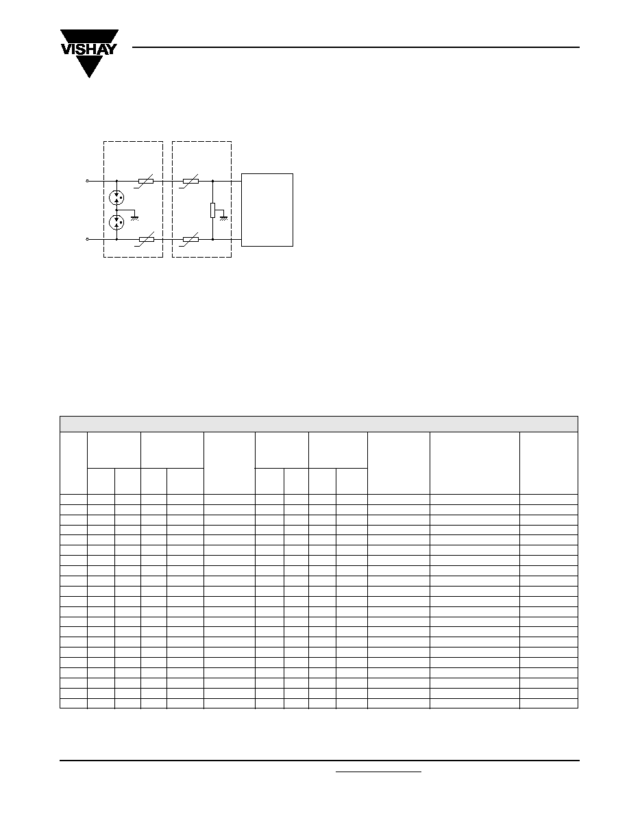
CCB913
SUBSCRIBER
LOOP
INTERFACE
CIRCUIT
(SLIC)
OR
TRANSFORMER
voltage
clamp
PTC
PTC
MDF
SECONDARY
PROTECTION
PRIMARY
PROTECTION
(OPTIONAL)
subscriber
lines
+
PTC
+
+
+
Typical telephone line showing where PTC thermistors
can be used for overcurrent protection.
ELECTRICAL DATA AND ORDERING INFORMATION
Notes
1. MDF: Main Distribution Frame; C.O.: Central Office Switching; T.E.: Subscriber Terminal Equipment; S.B.: Set-top Box.
2. UL 1434 approved types.
V
MAX.
(V)
NON-TRIP
CURRENT
RESISTANCE
MATCHED
PAIRS
TRIP
CURRENT
MAX.
TRIP TIME
at 25
∞
∞
∞
∞
C
APPLICATION
AREA
(1)
COMPATIBILITY
CATALOG
NUMBER
2322 ... .....
I
nt
(mA)
at T
(
∞
∞
∞
∞
C)
R
25
(
)
TOL
(%)
I
t
(mA)
at T
(
∞
∞
∞
∞
C)
t
t
(s)
at I
t
(mA)
220
70
70
25
±
20
1
200
25
2.5
1000
C.O.
K20/21
661 93048
230
100
70
10
±
20
1
250
25
3
1000
MDF; ISDN
K20/21
661 93147
245
60
70
70
+10/
-
15
no
180
25
60
220
C.O.
-
661 93025
245
75
70
33
±
20
±
5%
150
10
1.2
1000
C.O.
-
661 93037
245
70
70
25
±
15
no
200
25
20
400
C.O.
K20/21; FTCSE I31-24
661 93175
245
65
85
25
±
20
2%
200
25
3.40
650
C.O.
K20/21
661 93142
245
140
55
16
±
20
no
270
25
8
1000
T.E.
K20/21; FTCSE I31-21
662 93081
245
140
55
10
±
20
no
270
25
8
1000
T.E.
K20/21; FTCSE I31-21
662 93074
250
100
40
20
+10/
-
20
1
220
25
1
1 000
MDF
-
661 93118
250
70
70
25
±
20
1
175
25
1.3
1 000
MDF; C.O.
K20/21
661 93148
250
100
70
10
±
20
no
450
0
0.30
8 000
T.E.
K20/21
663 93025
285
135
95
8
±
25
0.5
400
25
6
1000
MDF; ISDN
K20/21
661 93078
300
100
70
16
±
25
no
250
25
2.0
1000
MDF; T.E.
K20/21
661 93121
350
100
70
10
±
20
no
270
25
4.0
1000
T.E.; S.B.
K20/21
661 93124
350
100
70
10
±
20
1
270
25
4.0
1000
C.O.
K20/21
661 93146
600
50
70
50
±
20
1
140
25
1
1000
C.O.
K20/21
661 93135
600
70
70
35
±
20
3
600
0
3
1000
C.O.
K20/21
661 93056
600
70
70
25
±
20
2%
170
25
4
700
C.O.
K20/21
661 93139
600
70
70
25
±
20
2%
170
25
8
700
C.O.
K20/21
662 93129
600
175
25
10
±
20
0.5
400
25
7
1000
C.O.
UL1459/GR1089
662 93114
(2)
600
175
25
10
±
20
no
400
25
7
1000
T.E.; S.B.
UL1459/GR1089
662 93131
(2)

2322 66. 9....
Vishay BCcomponents
PTC Thermistors, Overload Protection
For Telecommunication
www.vishay.com
For technical questions contact: nlr.europe@vishay.com
Document Number: 29070
164
Revision: 10-Oct-03
DIMENSIONS
in millimeters
COMPONENT OUTLINE
For dimensions see Specific Physical
Dimentions and Packaging table.
Lead pitch F = 5 mm +0.6/-0.1.
Lead thickness d = 0.6 mm ±10%.
CCB914
T
D
T
D
d
F
L
1
H
2
H
3
OVERCURRENT PROTECTION OF
TELECOMMUNICATION LINES
The PTC thermistor must protect the telephone line circuit
against overcurrent which may be caused by the following
examples:
∑
Surges due to lightning strikes on or near to the line plant.
∑
Short-term induction of alternating voltages from adjacent
power lines or railway systems, usually caused when these
lines or systems develop faults.
∑
Direct contact between telephone lines and power lines.
To provide good protection under such conditions a PTC
thermistor is connected in series with each line, usually as
secondary protection; see Typical Telephone Line drawing
on page 1. However, even with primary line protection
(usually a gas discharge tube), the PTC thermistor must fulfil
severe requirements.
Surge pulses of up to 2 kV can occur and in order to
withstand short-term power induction the PTC thermistor
must withstand high voltages. If the line has primary
protection a 220 V to 300 V PTC thermistor is adequate.
Without primary protection, however, a 600 V PTC device is
necessary. Vishay BCcomponents manufacturers a range of
PTC thermistors (see
Electrical Data and Ordering
Information Table ) covering both requirements.
In the case of direct contact between the telephone line and
a power line, the PTC thermistor must withstand very high
inrush power at normal mains voltage. Under such
conditions, overload currents of up to 10 A on a 230 V mains
could occur for up to several hours. To handle this power, the
resistance/temperature characteristic of the thermistor must
have a very steep slope and the ceramic must be extremely
homogeneous.
In case of overcurrent due to short-term induction of
alternating voltages, currents of several AMPs with voltages
as high as 650 V
RMS
can be present for several seconds
For standard high voltage applications, resistance values
from 25 to 50
are available. However, ISDN networks
which carry high-frequency sound and vision, need lower line
impedance.
Telecommunication designers are therefore demanding high
voltage thermistors with much lower R
25
values, which
places even greater demands on the manufacture of PTC
thermistors. For these applications PTC thermistors which
have a R
25
value of 10
with voltages in the
300 to 600 V
RMS
range are available.
In a typical telephone line application, two PTC thermistors
are used, one each for the tip and ring (or A and B) wire
together with their series resistors. For good line balance it is
important that the thermistor and resistor pairs are matched.
On request, Vishay BCcomponents can supply matched or
binned PTC thermistors with R
25
values matched to as close
as 0.5
.
SPECIFIC PHYSICAL DIMENSIONS AND PACKAGING
in millimeters
D
MAX.
T
MAX.
H
2
L
1
H
3
MAX.
PACKAGING
(1)(2)
CATALOG
NUMBER
2322 ... .....
7.0
4.0
3.5
±
0.5
-
11.0
taped H0 = 16 mm
661 91066
8.5
5.0
1.5 to 3.0
-
11.5
taped H0 = 16 mm
661 93048
7.0
4.0
2.0
±
0.5
-
9.8
taped H0 = 18 mm
661 93147
6.7
4.0
1.5 to 3.0
-
10.0
taped H0 = 18 mm
661 93025
7.0
5.0
1.5 to 3
-
10.0
taped H0 = 16 mm
661 93037
8.3
4.0
1.5 to 3.0
-
11.0
taped H0 = 18 mm
661 93175
(3)
6.8
4.3
1.5 to 3.0
-
10.1
taped H0 = 16 mm
661 93142
11
4.5
4.0
±
1.0
-
15.5
taped H0 = 16 mm
662 93081
11
4.5
4.0
±
1.0
-
15.5
taped H0 = 16 mm
662 93074
(3)
6.7
1.8
-
-
-
disc on tray
661 93118
7.0
4.0
2.0
±
0.5
-
9.8
taped H0 = 18 mm
661 93148
13.6
6.0
4.0
±
1.0
20
±
4.0
18.6
bulk
663 93025
(3)
8.3
5.0
1.5
±
0.5
20
±
3.0
10.3
bulk
661 93078

2322 66. 9....
PTC Thermistors, Overload Protection
For Telecommunication
Vishay BCcomponents
Document Number: 29070
For technical questions contact: nlr.europe@vishay.com
www.vishay.com
Revision: 10-Oct-03
165
Notes
1. Taped in accordance with
"IEC 60286-2"
; standard packaging: 1500 units/reel.
2. Naked disc ceramic for substrate mounting, available on request.
3. Insulated version is also available.
7.0
4.0
2.5
±
0.5
-
10.0
taped H0 = 16 mm
661 93121
8.5
4.0
2.5
±
0.5
4.1
±
0.5
11.5
bulk
661 93124
8.5
4.0
2.5
±
0.5
-
11.5
taped H0 = 16 mm
661 93146
8.5
4.0
2.5
±
0.5
4.1
±
0.5
11.5
bulk
661 93135
8.0
5.0
2.5
±
0.5
-
11.0
taped H0 = 16 mm
661 93056
8.5
4.0
2.0
±
0.5
-
11.0
taped H0 = 16 mm
661 93139
10.5
5.0
2.0 ±0.5
-
12.6
taped H0 = 16 mm
662 93129
13
5.5
4.0 ±1.0
20 min.
18.0
bulk
662 93114
13
5.5
4.0 ±1.0
20 min.
18.0
bulk
662 93131
D
MAX.
T
MAX.
H
2
L
1
H
3
MAX.
PACKAGING
(1)(2)
CATALOG
NUMBER
2322 ... .....
PACKAGING
All tape and reel specifications are in accordance with "IEC 60286-3". Basic dimensions are given in the drawing below, the
Dimensions of the Reel drawing, and tape and other Devices and Reel Dimensions tables.
TAPE SPECIFICATIONS
P0
D
P
d
P1
F
D0
L
W0
W1
W2
W
H 0
H
T
1
H 2
H 3
p
p
MBE473
15
5
o
o
0
0.2
h
h
t
T
Thermistors with D 12 mm on tape for 2322 66. 9....
For dimensions, see Tape
and other Devices table.
TAPE AND OTHER DEVICE DIMENSIONS in millimeters
SYMBOL
PARAMETER
DIMENSIONS TOLERANCE
REMARKS
D
body diameter
see Specific Physical
Dimensions table
±0.5
T
total maximum thickness
see Specific Physical Dimensions table
d
lead diameter
0.6
±10%
P
pitch between thermistors:
< 12 mm
12.7
±1
12 mm
25.4
±2
P
0
feed hole pitch
12.7
±0.3
cumulative pitch error ±1 mm/20 pitches
P
1
feed hole centre to lead centre
3.81
±0.7
guaranteed between component and tape
h
component alignment
0
±1.3

2322 66. 9....
Vishay BCcomponents
PTC Thermistors, Overload Protection
For Telecommunication
www.vishay.com
For technical questions contact: nlr.europe@vishay.com
Document Number: 29070
166
Revision: 10-Oct-03
F
lead to lead distance
5
+0.6 to -0.1
guaranteed between component and tape
h
component alignment
0
±2
W
tape width
18
+1 to -0.5
W
0
hold down tape width
12.3
-
W
1
hole position
9
±0.5
W
2
hold down tape position
3.0
-
H
1
component height
see Specific Physical Dimensions table
H
2
component body to seating plane
4
±1
H
3
component top to seating plane
see Specific Physical Dimensions table
H
0
lead-wire clinch height
16
±0.5
D
0
feed hole diameter
4
±0.2
t
total tape thickness
0.9
-
with cardboard tape 0.5 ±0.1 mm
L
length of snipped lead
11
-
SYMBOL
PARAMETER
DIMENSIONS TOLERANCE
REMARKS
CHARACTERISTICS CONCERNING TAPED THERMISTORS
REEL SPECIFICATIONS in millimeters
REEL DIMENSIONS in millimeters
PARAMETER
VALUE
Minimum pull out force of the component
5 N
Minimum pull off force of adhesive tape
6 N
Minimum tearing force tape
15 N
Maximum pull off force tape-reel
5 N
Storage conditions
Storage temperature range
-25 to +40 ∞C
Maximum relative humidity
80%
DIAMETER
W
1
W
2
MAX.
<12
42 ±1
56
12
46 ±1
60
Dimensions of the reel for 2322 66. 6...1/2/3
For W
1
and W
2
, see Reel Dimensions table
CCB614
22.5
30 +
1
-0
77
85.6
92
356
max.
18
3
W
1
W
2