 | –≠–ª–µ–∫—Ç—Ä–æ–Ω–Ω—ã–π –∫–æ–º–ø–æ–Ω–µ–Ω—Ç: 280105-02 | –°–∫–∞—á–∞—Ç—å:  PDF PDF  ZIP ZIP |

www.vishay.com
41
APD-240G064
Vishay Dale
Document Number: 37046
Revision 21-Dec-00
Plasma Panel Display Modules
240 x 64 Graphics Display with ASCII Input Controller,
DC/DC Converter and Drive Circuitry
The APD-240G064 is a dot matrix graphic display with an
array of 240 x 64 pixels available. The module is composed of a
highly reliable DC plasma display, ASCII input graphics control-
ler, DC converter and drive circuitry which are assembled to form
a rugged, slim profile display sub-system.
Interface to the APD-240G064 is through a parallel or serial inter-
face. The interface allows for efficient handshaking and flow of
bi-directional data. Vishay Dale's patented open construction
display technology assures a stable, flicker free screen.
FEATURES
∑ 240 x 64 pixel array for bright and vivid graphics
∑ Parallel interface or RS-232 serial interface
∑ Powerful software commands make display integration
simple and efficient
∑ + 5 to + 24VDC display voltage
ELECTROSTATIC CAUTION
Vishay Dale display panels use electrostatic sensitive
components. These assemblies should be unpacked and handled in an
ESD controlled area only. When shipping use packing materials designed for protection of electrostatic sensitive components.
Vishay Dale believes that the information described in this publication is accurate and reliable, and much care has been taken in its
preparation. However, no responsibility, financial or otherwise, is accepted for any consequences arising out of the use of this
information.
This information is subject to change without notice.
OPTICAL SPECIFICATIONS
Pixel Size: .019" [.483mm]
Pixel Array: 240 x 64
Luminance: 50 foot lamberts typical
Color: Neon orange.
Refresh Cycle: 65Hz
Viewing Angle: 150
∞ cone
Contrast Ratio: 30:1
ENVIRONMENTAL SPECIFICATIONS
Operating Temperature: 0
∞C to - 70∞C
Storage Temperature: - 20
∞C to - 85∞C
Operating Humidity: 95% RH non-condensing
Mechanical Shock: 30G
Vibration: 0.018" [.457mm] displacement amplitude from
10-50Hz, 2G acceleration from 50 to 2000Hz logarithmic
sweep rate
Mean Time Between Failure: 50,000 hours
STANDARD ELECTRICAL SPECIFICATIONS
DESCRIPTION
Panel Supply Voltage
Panel Supply Current
SYMBOL
VDC
IDC*
MIN.
5
--
TYP.
12.0
1.25
MAX.
24
2.50**
UNITS
V
A
DIMENSIONS in inches
Mounting Holes
.172 Dia. 4 Places
.200
4.330 3.780
.275
1.610
7.409
1.267
1.814
10.230
See Character Detail 'A'
.0285
.019 Sq. Typ.
.031
.325 Max.
1.3
Max.
Detail A
Matrix
Note: *at 12V
**at start-up

Document Number: 37046
Revision 21-Dec-00
www.vishay.com
42
APD-240G064
Vishay Dale
PARALLEL INTERFACE
J2, PARALLEL DATA CONNECTOR.
Mates with 3M Tyco AMP 746285-6, 26 pin, IDC connector.
Note: PAR should be jumper selected on jumper block W1 for
proper parallel interface operation.
*Note: The maximum VDC draw denotes a power up condition
when the DC converter starts. Typical duration is 15-30 mS.
*Unit may be powered from + 5V to + 24V. Contact factory for
current draw at voltages other than + 12V and pin connection J2.
+ 12V
± 0.6V
2.5A Max.*, 1.25 A Typ
.
VDC
POWER SUPPLY: (Recommended)
CONNECTOR
J1
PIN
1
2
3
4
SIGNAL
+ 12 V
GROUND
GROUND
Reserved
Mates to Tyco AMP *1-480424-0 housing (1 rqr.)
*350689-1 socket pins (4 rqr.)
POWER SUPPLY CONNECTION
Note: Input load is one 74 HCT type input with 4.7k to V
cc
. Outputs
are 74 HC type.
Once data write is complete, BUSY signal is output. BUSY
signal = "1" during data disposition and while the
communication buffer is full.
DATA WRITE: When WR changes from "0" to "1" while
US = "0" and RD = "1", data is latched.
DATA READ: When RD = "0" while US = "0". WR = "1", and
DP = "1", data may be read by the host.
POWER UP CONDITION
Immediately upon power up the following is set:
The module is in the text mode.
The screen will have a message printed as follows:
RAM OK
ROM OK
mm-dd-yy
This message indicates the hardware test has passed
successfully. The "mm-dd-yy" indicates the date the firm-
ware was released.
INPUT/OUTPUT TIMING DIAGRAM, J2
LOGIC LEVEL: L = 0.0 V minimum to 0.8 V maximum.
H = 2.2 V minimum to 5.0 V maximum..
X = Don't care.
DP
X
H
X
RD
H
L
X
WR
_|ØØ
H
X
US
L
L
H
FUNCTION
Write character or control code.
Read data from display while low.
Input/Output inhibited.
BU
L
X
X
PARALLEL INTERFACE
PIN
1, 3, 5, 7, 9, 11, 13, 15
17
21
6, 8, 12, 14, 16, 18, 20, 22
23
19
25
4
24
2, 26
10
DESCRIPTION
Data written to and read from the display unit through an 8 bit
bi-directional data bus.
Write data on low to high transmit.
Read data while low.
Not connected.
Reset display to power-up condition when low, operate while high.
Read and Write commands only influence display while US is low.
Blank display while BL is low but maintain cursor and data.
Display at full brightness when high or half brightness when low.
When BUSY is high, no further data or commands should be given.
Common to both power supply input and host data interface
.
Data is ready to be read when the DATA PRESENT signal is high.
FUNCTION
D0-D7 (Data Bus)
(input/output)
WRITE (WR)
(input)
READ (RD)
(input)
N/C
RESET
(input)
US (Unit Select)
(input)
BLANK (BL)
(input)
BRIGHT/DIM (input)
(BUSY (BU)
(output)
GROUND
DATA PRESENT
(DP) (output)
Power up RESET cycle on display module takes approxi-
mately
250 mS to complete. It is suggested the user wait for that
time period to elapse before entering data.
www.vishay.com
43
APD-240G064
Vishay Dale
Document Number: 37046
Revision 21-Dec-00
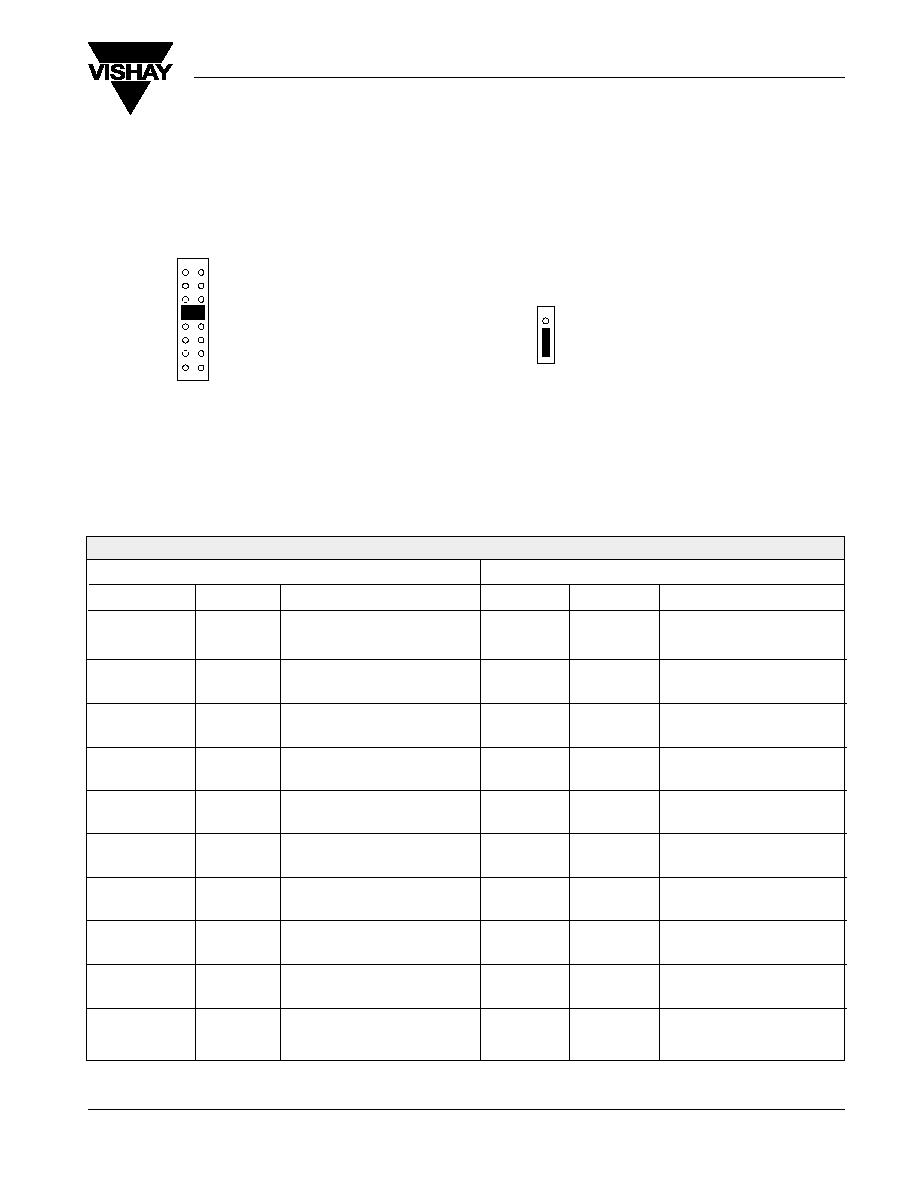
INTERFACING
W1 JUMPER
Shunt 1 pair of pins only on jumper W1 to select serial
interface baud rate, parallel interface operation, or self-test
functions. Shunt both OPT 1 and STEST to run demo.
W2 JUMPER
The W2 jumper selects the serial handshake busy line from
the host computer to the display for control of data flow from
the display. On Jumper W2, select "CTS" for host RTS to
display CTS handshaking, or "DSR" for host DTR to display
DSR handshaking. Selection does not affect parallel
interface operation.
1.2
2.4
4.8
9.6
19.2
OPT 1
PAR
S TEST
SELECTS
1200
Baud
2400
Baud
4800
Baud
9600
Baud (Factory setting)
19200
Baud
Self-Test demo
Parallel Interface Operation
Graphics Self-Test demo
SELECTS
Host DTR to display DSR handshaking
Host RTS to display CTS handshaking (factory
setting)
DSR
CTS
SERIAL INTERFACE PIN CONNECTIONS
DISPLAY CONNECTOR J3
DESCRIPTION
--
--
RxD
RTS
TxD
CTS
DTR
--
GND
--
db-25
--
--
3
4
2
5
20
--
7
--
db-9
--
--
2
7
3
8
4
--
5
--
10-PIN
1
2
3
4
5
6
7
8
9
10
db-9
1
6
2
7
3
8
4
9
5
--
DESCRIPTION
n/c (reserved)
n/c (reserved)
TxD (output)
CTS (input)
RxD (input)
RTS (output)
DSR (input)
n/c (reserved)
GND
n/c (reserved)
HOST CONNECTION
SERIAL INTERFACE
J3, SERIAL INTERFACE CONNECTOR.
Serial interface, mates with Tyco AMP 10-pin IDC type 746285 -1 or equivalent. Female db-9 connector option available.
The baud rate is jumper selected at jumper block W1 for 1200, 2400, 4800, 9600 or 19.2K baud.

Document Number: 37046
Revision 21-Dec-00
www.vishay.com
44
APD-240G064
Vishay Dale
COMMAND SET, TEXT MODE
(SOFTWARE INSTRUCTIONS)
The ASCII control code characters from 00h to 1Fh are reserved by the controller for the command interpreter. A brief listing
of the available commands and their description follows.
Note: *Indicates power up default.
HEX CODE
00-07
08
09
0A
0B
0C
0D
0E
0F
10
11
12
13
14
15
16
17
18
19
1A
1B
1C
1D
1E
1F
TEXT FUNCTIONS
NO FUNCTION.
BACK SPACE CURSOR: Moves the cursor 1 column
to the left in the current row. If the cursor is at the 1st column it will move to
the end of the previous line.
HORIZONTAL TAB: Moves the cursor 1 column to the right. Will wrap
around at the end of the screen. If mode is set to SCROLL, the screen will
scroll up one line at the last character position of the last row, if not in
SCROLL mode, the cursor will wrap to the HOME position.
LINE FEED: Moves cursor down one row while remaining in same column
position. If mode is set to SCROLL, and the cursor is at bottom row of screen,
the screen will move (scroll) up 1 row and bottom row will be cleared (filled
with spaces), when line feed is invoked. If not in SCROLL mode the cursor
will wrap to the first row.
VERTICAL TAB: Moves cursor up one row while remaining in the same
column position. The cursor will wrap to the bottom row after the top row.
CLEAR SCREEN: Fill the screen with blank characters, cursor moves to
HOME position.
CARRIAGE RETURN: Moves cursor to the first column of the present row.
HOME CURSOR: Moves cursor to the 1st character position of the 1st row,
the HOME position.
NO OPERATION.
NO OPERATION.
POSITION CURSOR: Moves cursor to a specified column, row address
depending upon next 2 bytes sent. The format is column, row.
SELECT CURSOR: Following byte selects cursor style
*
01 = Blinking Underbar
02 = Non-Blinking Underbar
03 = Blinking Block
04 = Cursor not Visible
NO OPERATION.
SELECT CHARACTER FONT: Following byte selects one of 4 character
generator fonts:
*
00 = ASCII, standard and inverse
01 = International
02 = International and Katakana
03 = International and Cyrillic
Set 8th data bit to logic "1". This is a useful command for programmers who
want to mix characters from both top and bottom of character set without
calculating offsets. (For example, using reverse video with the default font.)
NO OPERATION.
NO OPERATION.
NO OPERATION.
Set 8th data bit to logic "0". This disables the
previous command (15h).
RESERVED, do not use.
See ESCAPE control codes.
SET TO SCROLL MODE: Sets the display mode so that whenever the cursor
reaches the last position in the last column or a line feed occurs while cursor
is on last row, the screen will scroll up one row. The top row of data will be
lost and the bottom row of the display will be spaces.
SET TO AUTO WRAP MODE: In this mode, the cursor will automatically
wrap around to the next row. When the last character position on the screen
is reached, the cursor will return to HOME position.
BLANK DISPLAY: The display is blanked, but display memory is maintained
and new data can be entered.
UNBLANK DISPLAY: The display is restored/turned to active state.
NUMBER OF BYTES
1
1
1
1
1
1
1
1
3
2
2
1
1*
1
1*
1
1*

www.vishay.com
45
APD-240G064
Vishay Dale
Document Number: 37046
Revision 21-Dec-00
COMMAND SET, GRAPHIC MODE (SOFTWARE INSTRUCTIONS)
CURSOR LOCATION - All cursor locations are based upon Pixel location - NOT - character column and row locations. The
upper left hand corner is 000,000 (X, Y) while the lower right hand corner is 239, 063 (X, Y). The cursor auto-increments
based upon the character font size by the width of the font. The cursor is not visible in graphic mode.
WRITE LOGIC - Within most commands, the WRITE LOGIC byte must be included:
0 = SET PIXELS (turn-on foreground pixels)
1 = XOR PIXELS (invert foreground pixels)
2 = RESET PIXELS (turn-off foreground pixels)
3 = OVERWRITE (turn-on foreground and turn-off
background pixels, image load
and graphic text commands only)
FONT SIZE
The FONT SIZE must be written before text is written. There are three standard fonts included in the graphics mode:
1 = FONT 1, a 4 x 5 character in a 5 x 6 block
2 = FONT 2, a 5 x 7 character in a 6 x 8 block
3 = FONT 3, a 10 x 14 character in a 12 x 16 block
Refer to character set tables for supported characters and fonts.
Note: The LOGIC byte and FONT byte are sent in ASCII format.
DATA FORMAT
All addresses must be sent in ASCII format. Column and row positions begin at the upper left hand corner at address
000,000 (X, Y).
A pixel address consists of a column address followed by row address. Addresses are sent to the panel as a three character
ASCII sequence for column (x) followed by a three character ASCII sequence for row (y). An example is the upper left hand
pixel is 000,000 while the lower right hand corner is 239, 063.
Note: Spaces are shown in the graphic sequences only for clarity and must not occur in the actual commands transmitted to the panel.
GRAPHIC FUNCTIONS
GRAPHIC FUNCTIONS
CLEAR SCREEN: This command will clear the graphic screen to all pixels off (logic 0).
ESC C
TEXT WRITE: Logic byte (l), font byte (f), x, y starting address, ASCII text. Wrap around will occur.
ESC B l f xxx yyy aaaa..aaaa ESC \
SET PIXEL COMMAND: Logic byte (l), x, y pixel address, end of data delimiter.
ESC D l xxx yyy ESC \
(Single pixel)
ESC D l xxx yyy xxx yyy .......ESC \
(Continous)
SET GRAPHICS MODE:
ESC G
DRAW ELLIPSE: Logic byte, major axis intercept offset, minor axis intercept offset (axis's intercept offset is measured in
pixels from the center point), x, y center point, from angle theta (t), in degrees, to phi (p). A complete rotation would be from
001 to 360.
ESC H l mmm www xxx yyy ttt ppp
WRITE GRAPHIC IMAGE: Logic byte 1, y1 (upper left hand corner), 2, y2 (width and height), data.
ESC I l xxx yyy xxx yyy ddd ....
X1 start coordinate and X2 width must both be multiples of 8. The number of data bytes transmitted must be equal to (X2
width / 8)* Y2 height. The first data byte transmitted will map into the 8 pixels on the top line in the upper left hand corner of
the image with the least significant bit at the left and the most significant bit at the right. Successive bytes will write to the
next byte to the right. When all bytes are written for this line, the next byte will map into the left most byte of the next line
down.
Graphical representation of each data byte:
lsb x x x x x x msb
HEX
CODE
1B, 42
1B, 43
1B, 44
1B, 46
SET TEXT MODE:
ESC F
1B, 47
1B, 48
1B, 49