
For technical questions in the Americas, contact foilsupport1@vishay.com
For technical questions in Asia/Japan/Europe/Africa/Israel, contact foilsupport2@vishay.com
Document Number: 63044
Revision 18-Aug-04
www.vishay.com
92
2R, 3R, 4R
Vishay Foil Resistors
THROUGH HOLE
SALES
∑ ISRAEL: foilsales.israel@vishay.com ∑ FRANCE/SWITZERLAND/SOUTHERN EUROPE: foilsales.eusouth@vishay.com ∑ AMERICAS: foilsales.usa@vishay.com
∑ ASIA/JAPAN: foilsales.asia@vishay.com ∑ UK/HOLLAND/SCANDANAVIA: foilsales.eunorth@vishay.com ∑ GERMANY/CZECH REPUBLIC/AUSTRIA: foilsales.eucentral@vishay.com
FEATURES
∑ Resistance range each resistor: 1 to 150K
∑ TCR Tracking: to Ī 0.5ppm/įC
∑ Nominal TCR each resistor: See Figures 1 and 2 in data
sheet "7 Technical Reasons to Specify Bulk Metalģ Foil
Resistor Networks."
∑ Nominal tolerance ratio matching between resistors:
from Ī 0.005 to Ī 1%
∑ Absolute tolerance each resistor: Ī 1.0%, Ī 0.5%, Ī
0.25%, Ī 0.1%, Ī 0.05%, Ī 0.02%, Ī 0.01%, Ī 0.005%
∑ Power rating: 0.25 watts per resistor
Bulk Metal
ģ
Foil Technology
Molded Resistor Networks
Unitized Resistor Networks are comprised of Vishay S102C
elements combined and molded into single units. This method
of making networks yields some important advantages that
should be considered where space is not a limitation and
maximizing performance is important. To begin with, the leads
that emerge from the package go directly to the resistance
element (or an internal PC board), so the possibility of thermal
EMFs is very low. Next, the value range of the elements is large
(1 ohms to 150Kohms in a single foil element) and they can be
combined for even higher values. Finally, these elements
possess all the good features of discrete Bulk Metal
ģ
Foil
resistors, plus the ability to be further sorted for TCR track and
absolute match before encapsulation. These networks make
excellent voltage dividers, bridges, and attenuators where
performance and stability are important.
APPLICATIONS
∑ Differential amplifiers
∑ Gain defining resistors in digital voltmeters
∑ Ratio arms in bridge circuits
∑ Fuel metering systems
∑ Heads up displays
∑ Fire control systems
∑ Spacecraft instrumentation
∑ Naval weapons systems
∑ Binary Coded Decimal Ladder Networks
∑ Binary Ladders (A-D, D-A conversion, current and
voltage summing)
∑ Ratio and Ratio-matching Networks
∑ Bridge Networks
∑ Synchro Input and Summing Networks
∑ Resolver Networks
∑ Linear and Linear-summing Networks
∑ Decoder Networks
∑ Quadrature Bridge Networks
∑ Resistive Summing Networks
Resistance Temp Characteristic (TCR) Ī 2ppm/įC nominal
TCR Tracking To Reference Element
0.1ppm/įC to 4ppm/įC
(4)
Max Ambient Temp at Rated Wattage
+ 125įC
Max Ambient Temp at Zero Power
+ 175įC
Thermal Shock
R
(2)
0.002%
Ratio
(3)
0.002%
Low Temperature Operation R
0.005%
Ratio
0.002%
Short Time Overload
R
0.002%
Ratio
0.002%
Terminal Strength
R
0.001%
Ratio
0.001%
Resistance to Soldering Heat
R
0.002%
Ratio
0.001%
Moisture Resistance
R
0.003%
Ratio
0.003%
Shock
R
0.001%
Ratio
0.001%
Vibration, High Frequency
R
0.001%
Ratio
0.001%
Life
0.3 W @ +125įC
R
0.01%
Ratio
0.01%
0.02 W @ +60įC
R
0.003%
Ratio
0.001%
0.05 W @ +25įC
R
0.002%
Ratio
0.001%
High Temperature Exposure R
0.01%
Ratio
0.01%
Low Temperature Storage
R
0.002%
Ratio
0.002%
Insulation Resistance
> 500,000M
Dielectric Withstanding Voltage
No Change
Voltage Coefficient
(5)
R
< 0.1ppm/V
(5)
Ratio
< 0.1ppm/V
(5)
Noise
N/A
≠ 40dB (non-measurable)
Inductance
N/A
0.08ĶH
Capacitance
N/A
0.5pf
Rise Time
N/A
1ns @ 1K
Thermal EMF lead to lead
N/A
0.04ĶV/įC
Thermal EMF air circulation N/A
0.02ĶV/įC
Thermal EMF power
N/A
0.1ĶV for 20mW
Shelf Life
R
(6)
25ppm/year
Ratio
(6)
10ppm/year
(1) Typical is a designer's reference that represents 85% of
production. Most of the R's shown are maximums. To ensure
that all typical values are maximums a "burn-in" is required.
(2) R: absolute resistance change.
(3) Ratio: change in ratio between resistors within the
network package from before to after the specified test.
(4) Depending on construction and ratio value.
(5) Measured < 0.1ppm/V and within the measurement capability of
the equipment. Voltage coefficient is "essentially zero".
(6) 2 ppm when in hermetically sealed package.
TABLE 1 - TYPICAL
(1)
PERFORMANCE CHARACTERISTICS
Product may not
be to scale
For technical questions in the Americas, contact foilsupport1@vishay.com
For technical questions in Asia/Japan/Europe/Africa/Israel, contact foilsupport2@vishay.com
www.vishay.com
93
2R, 3R, 4R
Vishay Foil Resistors
Document Number: 63044
Revision 18-Aug-04
THROUGH HOLE
SALES
∑ ISRAEL: foilsales.israel@vishay.com ∑ FRANCE/SWITZERLAND/SOUTHERN EUROPE: foilsales.eusouth@vishay.com ∑ AMERICAS: foilsales.usa@vishay.com
∑ ASIA/JAPAN: foilsales.asia@vishay.com ∑ UK/HOLLAND/SCANDANAVIA: foilsales.eunorth@vishay.com ∑ GERMANY/CZECH REPUBLIC/AUSTRIA: foilsales.eucentral@vishay.com
2
3
5
R2
R3
1
R1
4
2
3
4
R2
R3
1
R1
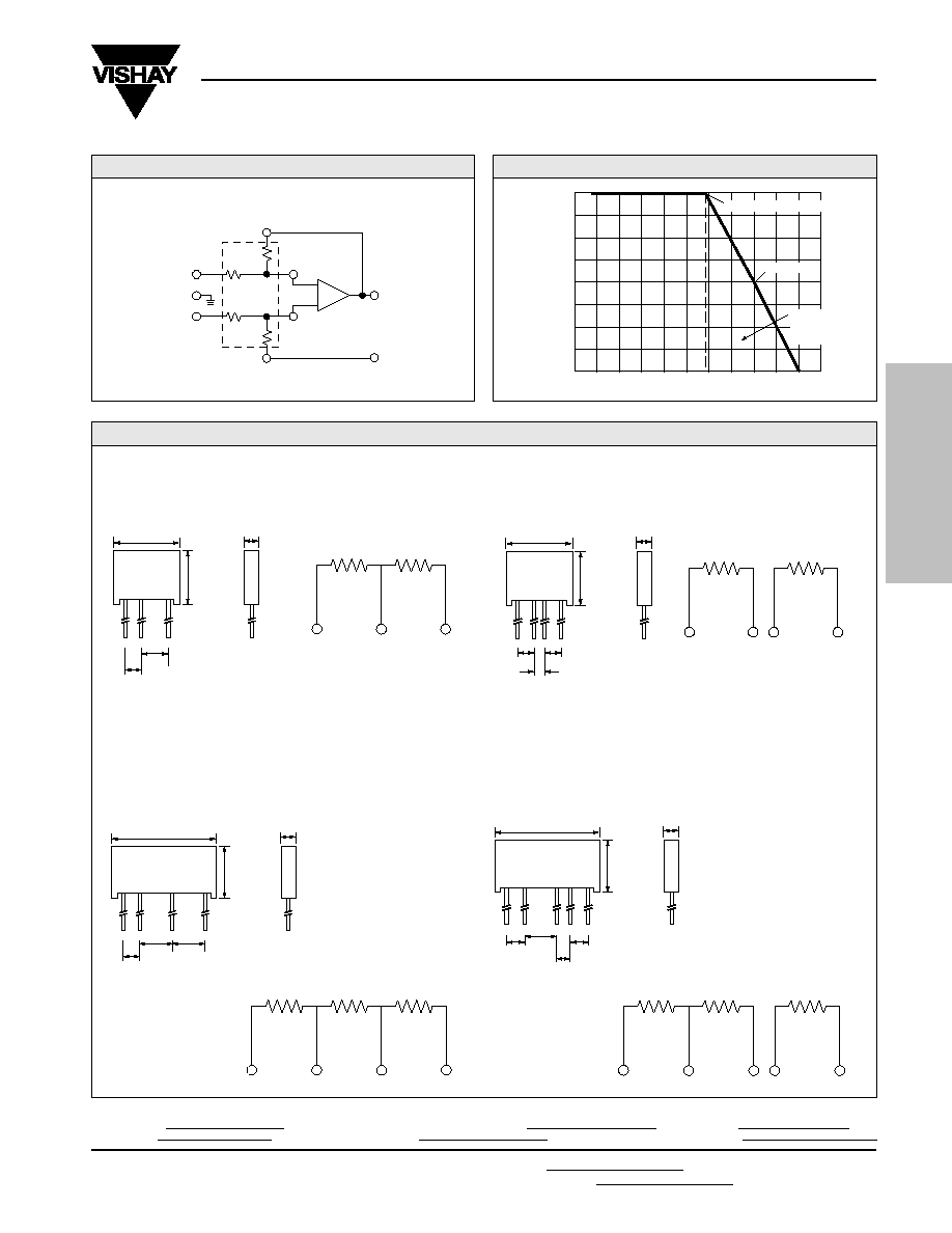
MODEL 300192
MODEL 300193
2
3
R2
1
R1
1
2
4
R1
R2
3
FIGURE 3 - MOLDED 2R, 3R, 4R RESISTOR NETWORK DIMENSIONS AND CIRCUIT DESIGN in inches (millimeters)
MODEL 300190
MODEL 300191
Bulk Metal
ģ
Foil Technology
Voltage Dividers, Bridge Circuits, Attenuators
1
0.160 Max
(4.06)
2
3
0.413
(10.49)
Max
0.150
(3.81)
0.250
(6.35)
Tol.: Ī0.010" (0.254 mm)
Lead Length 0.750" (19.05 mm) Min
0.575 (14.605) Max
0.160 Max
(4.06)
0.413
(10.49)
Max
1
2
4
0.150
(3.81)
3
0.150
(3.81)
0.100
(2.54)
Tol.: Ī0.010" (0.254 mm)
Lead Length 0.750" (19.05 mm) Min
0.575 (14.605) Max
Tol.: Ī0.010" (0.254 mm)
Lead Length 0.750" (19.05 mm) Min
0.820 (20.828) Max
1
0.160 Max
(4.06)
2
4
0.413
(10.490)
Max
0.150
(3.81)
3
0.250
(6.35)
0.250
(6.35)
0.160 Max
(4.06)
0.413
(10.490)
Max
1
2
5
0.150
(3.81)
3
0.150
(3.81)
0.250
(6.35)
4
0.100
(2.54)
Tol.: Ī0.010" (0.254 mm)
Lead Length 0.750" (19.05 mm) Min
0.820 (20.828) Max
R1
R4
R2
R3
A
E1
E2
E3
APPLICATION EXAMPLE
FIGURE 1- VISHAY MODEL 300198 NETWORK
200%
175%
150%
125%
100%
75%
50%
25%
0
≠75
≠50
≠25
0
+25
+50
+75
+100 +125 +150 +175 +200
Ambient Temperature (įC)
Percent of Rated Power @ +125
į
C
≠55įC
+70įC
Double Rated Power
Rated Power
Safe operation
for <150 ppm
R after 2,000
hours load-life.
FIGURE 2 - POWER DERATIMG CURVE
For technical questions in the Americas, contact foilsupport1@vishay.com
For technical questions in Asia/Japan/Europe/Africa/Israel, contact foilsupport2@vishay.com
Document Number: 63044
Revision 18-Aug-04
www.vishay.com
94
2R, 3R, 4R
Vishay Foil Resistors
THROUGH HOLE
SALES
∑ ISRAEL: foilsales.israel@vishay.com ∑ FRANCE/SWITZERLAND/SOUTHERN EUROPE: foilsales.eusouth@vishay.com ∑ AMERICAS: foilsales.usa@vishay.com
∑ ASIA/JAPAN: foilsales.asia@vishay.com ∑ UK/HOLLAND/SCANDANAVIA: foilsales.eunorth@vishay.com ∑ GERMANY/CZECH REPUBLIC/AUSTRIA: foilsales.eucentral@vishay.com
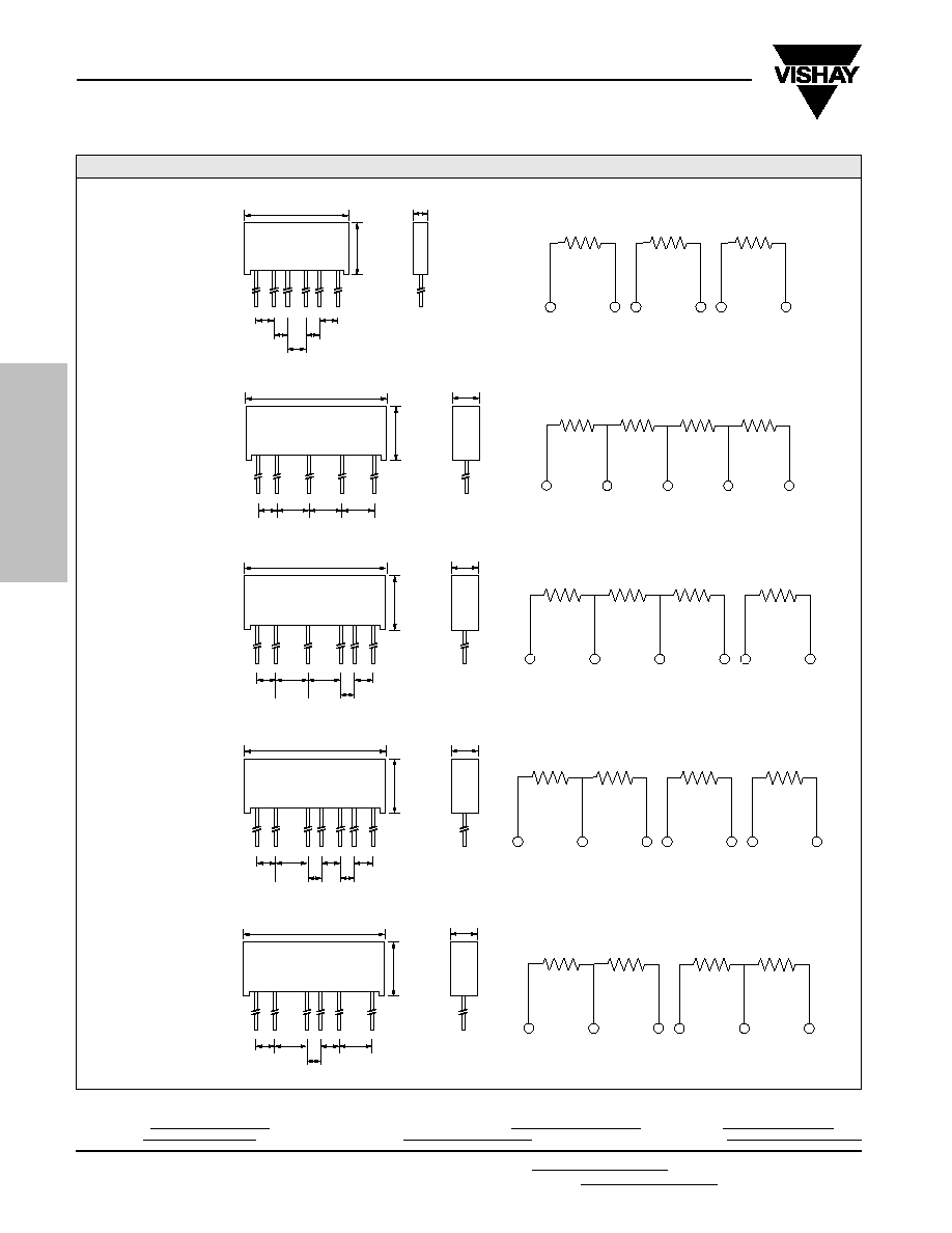
FIGURE 4 - MOLDED 2R, 3R, 4R RESISTOR NETWORK DIMENSIONS AND CIRCUIT DESIGN in inches (millimeters)
2
3
R2
R3
1
R1
5
6
R4
4
2
3
5
R2
R3
1
R1
6
7
R4
4
2
3
R2
R3
1
R1
5
6
R4
4
2
3
4
R2
R3
1
R1
5
R4
MODEL 300194
1
2
4
R1
R2
3
6
R3
5
MODEL 300198
MODEL 300196
MODEL 300197
MODEL 300195
Bulk Metal
ģ
Foil Technology
Voltage Dividers, Bridge Circuits, Attenuators
0.150
(3.81)
0.150
(3.81)
0.100
(2.54)
0.820 (20.828) Max
0.160 Max
(4.06)
Tol.: Ī0.010" (0.254 mm)
Lead Length 0.750" (19.05 mm) Min
0.413
(10.490)
Max
1
2
6
0.150
(3.81)
4
5
3
0.100
(2.54)
Tol.: Ī0.010" (0.254 mm)
Lead Length 0.750" (19.05 mm) Min
0.250
(6.35)
0.250
(6.35)
0.413
(10.490)
max
1.20 (30.48) Max
0.245 (6.223)
3
0.250
(6.35)
5
4
1
2
0.150
(3.81)
0.413
(10.490)
max
0.245 (6.223)
3
0.250
(6.35)
5
0.150
(3.81)
6
0.100
(2.54)
4
0.250
(6.35)
1
2
0.150
(3.81)
Tol.: Ī0.010" (0.254 mm)
Lead Length 0.750" (19.05 mm) Min
1.20 (30.48) Max
0.413
(10.490)
max
0.245 (6.223)
3
0.250
(6.35)
6
0.150
(3.81)
7
0.100
(2.54)
5
0.100
(2.54)
0.150
(3.81)
1
2
0.150
(3.81)
4
Tol.: Ī0.010" (0.254 mm)
Lead Length 0.750" (19.05 mm) Min
1.20 (30.48) Max
0.250
(6.35)
0.150
(3.81)
0.413
(10.490)
max
0.245 (6.223)
3
0.250
(6.35)
6
5
0.100
(2.54)
1
2
0.150
(3.81)
4
Tol.: Ī0.010" (0.254 mm)
Lead Length 0.750" (19.05 mm) Min
1.20 (30.48) Max

For technical questions in the Americas, contact foilsupport1@vishay.com
For technical questions in Asia/Japan/Europe/Africa/Israel, contact foilsupport2@vishay.com
www.vishay.com
95
2R, 3R, 4R
Vishay Foil Resistors
Document Number: 63044
Revision 18-Aug-04
THROUGH HOLE
SALES
∑ ISRAEL: foilsales.israel@vishay.com ∑ FRANCE/SWITZERLAND/SOUTHERN EUROPE: foilsales.eusouth@vishay.com ∑ AMERICAS: foilsales.usa@vishay.com
∑ ASIA/JAPAN: foilsales.asia@vishay.com ∑ UK/HOLLAND/SCANDANAVIA: foilsales.eunorth@vishay.com ∑ GERMANY/CZECH REPUBLIC/AUSTRIA: foilsales.eucentral@vishay.com
FIGURE 5 - MOLDED 2R, 3R, 4R RESISTOR NETWORK DIMENSIONS AND CIRCUIT DESIGN in inches (millimeters)
MODEL 300212
2
3
R1
4
1
R2
R3
R4
5
1
2
4
R1
R2
3
6
R3
5
8
R4
7
MODEL 300199
MODEL 300211
2
3
R1
4
1
R2
R3
R4
5
MODEL 300210
ORDERING INFORMATION - MOLDED 2R, 3R AND 4R RESISTOR NETWORKS
Networks are built to your requirements. Send your schematic and electrical requirements to the Applications Engineering
Department. (See data sheet "Network Worksheet.") A unique part number will be assigned which defines all aspects of your
network.
1
2
3
4
R1
R2
R3
Bulk Metal
ģ
Foil Technology
Voltage Dividers, Bridge Circuits, Attenuators
0.150
(3.81)
0.100
(2.54)
0.150
(3.81)
0.100
(2.54)
0.150
(3.81)
0.413
(10.490)
max
0.245 (6.223)
3
6
8
5
1
2
0.150
(3.81)
4
0.100
(2.54)
7
Tol.: Ī0.010" (0.254 mm)
Lead Length 0.750" (19.05 mm) Min
1.20 (30.48) Max
0.250
(6.35)
0.160 Max
(4.06)
0.413
(10.490)
Max
1
4
0.250
(6.35)
0.150
(3.81)
3
2
Tol.: Ī0.010" (0.254 mm)
Lead Length 0.750" (19.05 mm) Min
0.820 (20.828) Max
0.413
(10.490)
max
0.245 (6.223)
3
0.250
(6.35)
5
0.150
(3.81)
6
0.100
(2.54)
4
0.250
(6.35)
1
2
0.150
(3.81)
Tol.: Ī0.010" (0.254 mm)
Lead Length 0.750" (19.05 mm) Min
1.20 (30.48) Max
Tol.: Ī0.010" (0.254 mm)
Lead Length 0.750" (19.05 mm) Min
0.250
(6.35)
0.250
(6.35)
0.413
(10.490)
max
1.20 (30.48) Max
0.245 (6.223)
3
0.250
(6.35)
5
4
1
2
0.150
(3.81)