 | –≠–ª–µ–∫—Ç—Ä–æ–Ω–Ω—ã–π –∫–æ–º–ø–æ–Ω–µ–Ω—Ç: 305C20 | –°–∫–∞—á–∞—Ç—å:  PDF PDF  ZIP ZIP |
www.vishay.com
3
305C Series
Vishay Cera-Mite
ceramite.support@vishay.com
Document Number: 23086
Revision 14-May-02
∑ ECONOMICAL SOLID STATE TORQUE ASSIST FOR HEAT PUMPS, ROOM AIR, COMMERCIAL
AND RESIDENTIAL AIR CONDITIONING AND REFRIGERATION SYSTEMS
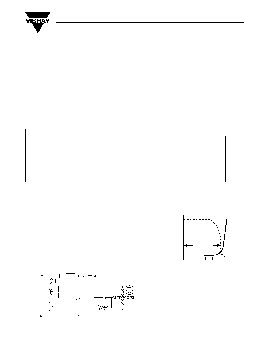
RELATIVE COMPARISON OF VARIOUS MOTOR STARTING METHODS
Table 1
Fig T-2
TYPICAL PTCR CHARACTERISTICS
AS A MOTOR START DEVICE
Fig T-3
MECHANICAL ELECTRICAL FINANCIAL
PANEL SENSITIVE TO ACCELERATION ACCELERATION RESET INVENTORY
STARTING EASE OF SPACE MOUNTING TORQUE (SWITCH) TIME EMI/RFI MIX PURCHASED
METHOD WIRING REQUIRED DIRECTION PRODUCED TIME REQUIRED GENERATED TECHNOLOGY REQUIRED RELIABILITY COST
PTCR Starter Simple Lowest No Lowest Fixed 3 - 5 No Solid State
Lowest Highest Lowest
2 Wire Minutes
Start Cap with Moderate Medium Yes Medium Fixed 2 - 5 No Solid State
Medium Medium Medium
PTCR Acting as 2 or 3 Minutes
A Current Relay Wire
Start Cap used Difficult Highest Yes Highest Variable None Yes Electro
Highest Lowest Highest
With Potential or 4 or 5 Based on Mechanical
Current Relay Wire Motor Speed
Positive Temperature Coefficient Resistors have been
used for many years in millions of HVAC applications to
provide starting torque assistance to Permanent Split
Capacitor (PSC) single phase compressor motors.
Sizes
are available to cover the full range of 120/240 volt
PSC compressor motors.
Safety Agency Recognition
Vishay Cera-Mite motor start PTCRs are recognized by
Underwriter Laboratories file E97640 in accordance with
Standard for Thermistor Type Devices UL 1434; and Canadian
Standards C22.2 No. 0-1991.
Three methods have historically been employed to generate
starting torque for PSC motors. All are well-proven technolo-
gies and may be compared relative to one another based
upon categories shown below.
The importance of each category is dependent upon the
motor application and industry sector.
In general, if the PTCR starter produces sufficient starting
torque, it is considered the simplest and most economical
choice.
SIMPLIFIED PTCR STARTING DIAGRAM
Start Sequence. When starting the
compressor, contactor (M) closes;
the PTCR, which is at low resistance,
provides starting current to the motor's
auxiliary winding. After time delay (t),
the current passing through the PTCR
causes it to heat and "switch" to a very
high resistance. At this point the motor is
up to speed and the run capacitor (CR)
determines the current in the auxiliary
winding. The PTCR remains hot
and at high resistance as long
as voltage remains on the circuit.
When contactor (M) opens, shutting
off voltage to the compressor,
the PTCR cools to its initial low
resistance and is again ready to provide
torque assist on the next startup.
Restart. It is important to provide
time between motor starts to allow
the PTCR to cool to near its initial
temperature. This time is usually
3 to 5 minutes and is determined by
the thermostat (THERM) or separate
time-delay relay (TR). Attempts to
restart in less time may be successful
depending on compressor equaliza-
tion, line voltage, temperature, and
other conditions. If the motor were to
stall in a locked-rotor state, overload
device (PD or TS) would open the
line and a further time delay would
occur until the motor overload is
reset. Motor start PTCRs are applied
to compressors having means to
equalize pressure during shutdown.
PTCR Motor Start Packages
PSC Single Phase Motor Start Assist
20.0
PD
C
R
MAIN
PTCR
PSC
MOTOR
AUX.
TS
Internal
Motor
Winding
Overtemp.
Switch
Protective
Device
Optional OFF
Time Delay
Relay
TR
M
Protective
Device
L
2
M
M
AC Line
120 or 240
VOLTS AC
T
HERM
TR
L
1
Low Voltage Control Transformers Not Shown
M
PTCR Temperature ∞C
RESISTANCE
CURRENT
Switch Time (t)
PTCR
Current
(Amperes)
20.0
0.02
50
100
150
1,000
10,000
10
100
PTCR Resistance (ohms)
www.vishay.com
4
305C Series
Vishay Cera-Mite
ceramite.support@vishay.com
Document Number: 23086
Revision 14-May-02
The use of a PTCR start assist insures sufficient acceleration
torque to overcome not only breakaway friction, but also
parasitic asynchronous torques associated with the 5th and
7th motor harmonics or lamination slot harmonics.
ACCELERATION TIME CONSIDERATIONS
The time to accelerate a rotating machine is:
RPM x WK
2
(lb ft
2
)
Accelerating Time (Seconds) =
Avg. Torque (lb ft) x 308
(Avg. Torque = Curve B - Curve A)
1. If (Curve B - Curve A) is zero or less, the motor may stall.
2. In calculating torque available from Curve B, allowance
should be made for cusps in the torque curve due
to harmonics. The time needed to accelerate from rest
to 1/2 speed is critical, as the average torque available
in this region is limited. Select a PTCR with sufficient
switching time (t) to accelerate the compressor.
3. Scroll and rotary compressors may have less breakaway
torque than shown.
4. A compressor with no equalization may require over
100% starting torqe and time as long as several seconds.
PTCR starters not recommended.
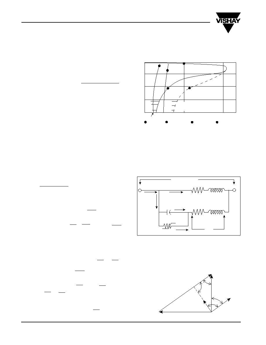
Fig T-4
Fig T-6
Simplified Voltage Diagram of the PSC Motor at Operating
Speed
*I
A
(auxiliary current) leads I
M
(main current)
by 80∞ to 90∞ when C (run capacitor) is
chosen for balanced operation at 3/4 to
full load. Line Power Factor = sine 2
Fig T-5
PTCR Motor Start Packages
HP x 746
I
L
(run) =
I
L
(start)
6 x
I
L
run
V
M
x pf x eff
For running conditions:
I
L
If
V
aux
= V
M,
then
I
M
and
I
aux
=
2
I
L
V
M
V
M
If
V
aux
V
M
,
then
I
aux =
x and Z
aux =
2
V
aux
I
aux
For the greatest starting torque, PTCR should be chosen to make:
V
M
x
I
M
= V
aux
x
I
aux
. In many cases the auxiliary Volt-
Amperes are limited to about 50% of the main winding
Volt-Amperes to get 50% - 70% rated torque.
Then at start, with PTCR in series: Z'
aux
= R
PTCR
+ Z
aux
V
M
I
R
start
through PTCR =
Z'
aux
V
M
1
I
C start
through Run Cap = ; Xc = ohms
Xc 2
f C
I
aux start
=
I
R start
+
I
C start
If Z
aux
is low impedance, less than 10% of R
PTCR
then it can be ignored and
I
PTCR
at start = V
M
R
PTCR
This closely approximates the condition for motors over 1/2 HP.
START AND ACCELERATION TORQUES
SINGLE PHASE PSC HIGH EFFICIENCY COMPRESSORS
CONSIDERATIONS FOR CURRENT IN PTCR
APPROXIMATE EQUIVALENT CIRCUIT PSC MOTOR AT ZERO SPEED
100
75
50
25
0
5th
7th
Slot
Percent Rated Speed
100
200
A
2
A
1
B
1
B
2
Line Voltage V
M
I
aux
I
M
I
c
R
M *
X
M *
L
2
C
PTCR
X
aux
R
aux
*R and X are total of stator and rotor
V
aux
L
1
I
L
I
R
CURVE B2
Motor speed
versus torque
with run cap
and PTCR
CURVE B1
Motor speed
versus torque
with run cap
only
CURVE A2
Torque req'd to
accelerate
compressor at
partial differential
pressure
CURVE A1
Torque req'd
to accelerate
unloaded
compressor
Cold Breakaway Torque
Percent Rated Torque
Full Load
Operating Point
Possible Region of
Harmonic Torques
max.
Torque
V
A
I
A
I
M
V
M
Applied
Voltage
V
PTCR
=
V
C
=
I
A
C
www.vishay.com
5
305C Series
Vishay Cera-Mite
ceramite.support@vishay.com
Document Number: 23086
Revision 14-May-02
START CAPACITOR PTCR VALUE
50 microfarads 50 ohms
75 microfarads 37.5 ohms
100 microfarads 25 ohms
125 microfarads 20 ohms
200 microfarads 12.5 ohms
250 microfarads 10 ohms
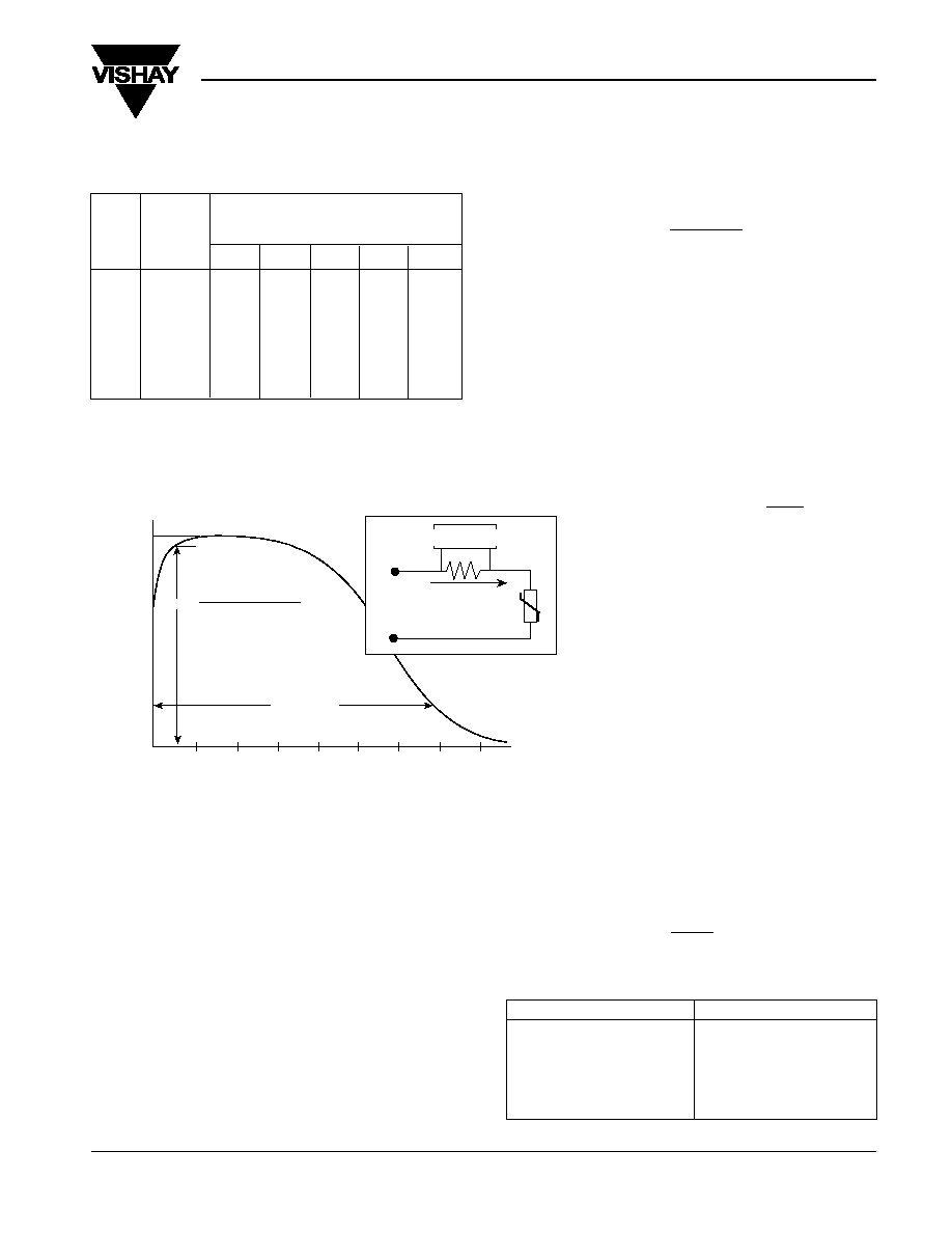
EFFECT OF PTC RESISTANCE ON STARTING TORQUE OF PSC MOTORS
A. Rated torque is the torque at full speed rated load.
It is calculated as:
HP x 5250
Torque (lb - ft) =
RPM
The range shown includes both normal slip and high
efficiency low slip motors. Starting torque varies as:
(Line
Voltage)2 .
B. Figure T- 4 shows effect of using PTCR to increase
starting torque. For reciprocating compressors, it is
advised to choose a resistance value that gives at least
50% rated torque at locked rotor. Scroll and rotary
compressors may require less torque.
Fig T-7
Table 2
Table 3
LOCKED ROTOR STARTING TORQUE WITH RUN CAP
TORQUE WITH RUN AND PTCR (% RATED TORQUE) (SEE B)
MOTOR HP CAP ONLY RESISTANCE (Rdyn)
(TABLE 4) % RATED TORQUE
(NOTE 7) (SEE A) 50 ohm 25 ohm 20 ohm 12.5 ohm 10 ohm
0.5 25% to 35% 70 - 100% 80 - 100% NA NA NA
1 25% to 35% 50 - 70% 70 - 100% NA NA NA
2 20% to 30% 40 - 60% 60 - 90% 70 - 100% 70 - 100% 80 - 100%
3.5 20% to 30% NA 40 - 60% 50 - 85% 60 - 90% 70 - 100%
5 15% to 25% NA NA 40 - 60% 50 - 75% 60 - 90%
6.5 15% to 25% NA NA NA 40 - 70% 50 - 80%
1
X
c
=
2
fC
PTCR Motor Start Packages
TYPICAL PTCR CURRENT VS. TIME SHOWING DEFINITION OF RDYN AND SWITCH TIME (T)
0
0.1
0.2
0.3
0.4
0.5
0.6
0.7
0.8
Applied Voltage (E
RMS
)
I
PTCR
at .05 Sec
R
DYN
=
Peak
Current
20% Peak
Current
I
PTCR
Amperes
(RMS)
(Normalized)
Time to Switch (Seconds)
Motor
Contactor
Closes
PTCR Switchout
Switch Time (t)
OSCILLOSCOPE
SHUNT
I
PTCR
E
RMS
PTCR
R
DYN
Time (t)
KM (130∞C - T
0
)
V
2
PTCR
M = PTCR mass
T
0
= PTCR temp at time 0
K = 0.75 J/g/ ∞C
START CAPACITOR REPLACEMENT
Capacitor Starting Comparison
Some PSC motors have historically been started with a
capacitor and relay. To deliver the same starting current as
a start capacitor, a PTCR resistance is available for approxi-
mately equal ohms. Table 3 can be used for conversion.
Even though the start current may be the same, the start
torques may differ depending on the motor design. The PTCR
has a fixed time built in. The start capacitor will
stay in the circuit until a relay switches it out. The
longer time provided by the capacitor and relay may
be needed on applications where equalization is
not present or adequate reset time is not available.
STARTING CURRENT APPROXIMATION
BASED ON

www.vishay.com
6
305C Series
Vishay Cera-Mite
ceramite.support@vishay.com
Document Number: 23086
Revision 14-May-02
VISHAY
CERA-MITE RESISTANCE (OHMS) SWITCH TIME CURRENT MAX. VOLTAGE AVG. POWER COMPRESSOR
PART CASE R
DYN
R
0
(T) SECONDS
RATING RATING DISSIPATION RANGE
NUMBER STYLE ± 20%
± 30% @ 230V AMPERES VOLTS, RMS WATTS BTU (000) HP
305C20* C 25 35 0.25 10 410 3.5
10 - 28 0.75 - 2.0
305C21 C 35 50 0.35 8 410 3.5
8 - 18 0.5 - 1.5
305C22* C 50 75 0.50 6 410 3.5
5 - 12 0
..25 - 1.0
305C19* B 20 30 0.50 18 500 7
20 - 50 1.5 - 4.0
305C12* B 25 40 0.60 15 500 7
18 - 42 1.5 - 3.5
305C2 B 50 85 1.00 12 500 7
10 - 25 1.0 - 2.5
305C9* A 10 15 0.50 36 500 9
28 - 68 3.0 - 7.0
305C11 A 12.5 20 0.60 30 500 9
28 - 62 3.0 - 6.0
305C1* A 25 42.5 1.00 24 500 9
14 - 36 1.5 - 3.5
Note 1 Note 2 Note 3 Note 4 Note 5 Note 6 Note 7
PTCR Motor Start Packages
PTCR SELECTION
∑ Choosing the best PTCR for an application is a simple
matter. See Table 4 and Table 2. Vishay Cera-Mite PTCRs
are available in three case sizes (A, B, and C).
∑ Table 4 indicates the correct case size for the application.
Table 2 shows how to choose the correct resistance
value.
∑ Using a device too small or resistance too high
will give inadequate starting performance. An oversize
device will not harm the motor, but may not be optimum with
regards to acceleration dynamics, or power dissipation.
∑ The PTCR is generally self protecting when applied within
the voltage and current ratings.
Table 4
PTCR MOTOR START SELECTION CHART
Note 1
Part number is stamped on the device
for UL recognition. The customer
part number will also include 1 or
3 character alpha-numeric suffix to
designate mounting bracket, customer
marking, wire jumper, or other acces-
sory furnished. The suffix is not marked
on the part. Certified outline drawing
and complete part number will be
furnished on request for specific
applications. (Example: 305C19K01.)
Mounting brackets and other acces-
sories are shipped in separate boxes
to simplify installation in end use
equipment.
Note 2
R
DYN
is nominal resistance equal to E/I
when 230 volts, 60 Hz is applied (See
Fig T-7). This resistance determines
current and starting torque at the
moment of application of voltage to
the motor and can be measured with
an oscilloscope.
For receiving inspection or routine
trouble shooting, the D.C. resistance
(Ro) as measured with an ohmmeter
is approximately 50% greater. For
example: 305C20 measured with an
ohm meter would be 35 ohms ± 30%
tolerance.
Note 3
Resistance values are duplicated in
several case sizes (ie: 305C20, C12,
and C1) to provide longer switch time
(t) and higher current ratings (See
Fig T-7). Larger parts may be needed
for more difficult starting conditions
(voltage or temperature) or may be
used for accelerating fans against
back pressure.
Note 4
Maximum current in the PTCR is
determined by
Max Line Voltage
Min R
DYN
Motor auxiliary winding impedance
is usually small compared to PTCR
resistance, and does not materially
affect PTCR current.
Current in PTCR is a percentage of
the full motor inrush (locked rotor)
current; usually 30% to 50% (See
Fig T-5).
Note 5
In application, the maximum voltage is
the voltage that appears across the
run capacitor at rated speed, high line,
light load. This is not the applied line
voltage (See Fig T-6).
THESE DEVICES ARE INTENDED
FOR APPLICATION ON 240 VOLT
LINES OR SYSTEMS WITH MAXI-
MUM LINE VOLTAGE UP TO 264
VOLTS. The 305C20, 21 and 22 are
also used on 120 volt systems where
the motor is designed to use same
run capacitor and PTCR as equivalent
230 volt compressor.
Note 6
This is the power used to keep the
PTCR switched off under full load
running conditions at typical ambient
temperature.
Note 7
BTU and horsepower ranges are
for reference only. PTCR may be
applied outside those ranges as long
as maximum voltage and maximum
current are not exceeded. Scroll
and rotary compressors may require
less starting assistance allowing use
of smaller devices.
* Preferred Values
www.vishay.com
7
305C Series
Vishay Cera-Mite
ceramite.support@vishay.com
Document Number: 23086
Revision 14-May-02
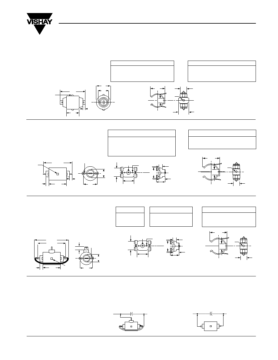
CASE STYLE C
Case Style C is a 2-terminal single pellet
device with current carrying capacity
up to 10 amperes. It is furnished with a
round mounting bracket.
Round Bracket -- Spring Steel Phosphate &
Oil Finish. Accepts #6 Sheet Metal Screw
Round Bracket -- Spring Steel Phos-
phate & Oil Finish. Accepts #6 Sheet
Metal Screw
Fig T-8
U-Bracket -- Spring Steel Zinc Dichromate
Finish. Accepts #8 Sheet Metal Screw
OPERATING TEMPERATURE
Under normal operation, the ceramic
pellet inside the case reaches a tem-
perature of 150∞C. The plastic case
material has been recognized by UL for
operation up to this temperature. The
actual temperature on the outside of the
case will be approximately 100∞C while
the motor is running. An appropriate
mounting location and 105∞C, 600 volt
wiring are recommended.
Fig T-10
PTCR Motor Start Packages
DIMENSIONS FOR PTCR MOTOR START DEVICES - IN INCHES
∑ PACKAGED MOTOR START PTCRs ARE OFFERED IN THREE DIFFERENT CASE SIZES TO
ACCOMMODATE THE RANGE OF PSC COMPRESSOR MOTORS SERVED.
MOUNTING BRACKET
36-520M -- Round
CASE C
305C20 -- Black
305C21 -- Black
305C22 -- Black
1.780
max
.810
.880
.200
max
Weld
Projection (2)
.050 HT. TYP.
.175 WD. TYP.
.920
.980
.609
.641
.329
.358
.579
.609
.135
.140 DIA.
.298
.328
.975
1.025
CASE STYLE B
Case Style B is a 2-terminal single
pellet unit with current carrying capacity
up to 18 amperes. Depending upon
the model, either a U-shaped or round
bracket is furnished.
MOUNTING BRACKET
7-36-5C -- U-Shaped
36-520H -- Round
CASE B
305C2 -- Black
305C12
-- Black or Blue
305C19
-- Blue
Fig T-9
2.37 max
.20
TYP.
.25 max.
2 places
Weld
Projection (3)
.050 HT. TYP.
.175 WD. TYP.
1.50
max
.650
max
.15 OD x .055 HT
4 places
1.344
1.406
1.430
1.530
.990
1.010
.213
.223
.110 Nail Pierce
.120 REF.
.550
.580
1.490
1.510
1.05
1.44
max
DIA.
1.475
1.525
.579
.609
.135
.140 DIA.
.298
.328
CASE STYLE A
Case Style A is a 3-terminal device that
incorporates two pellets in parallel, resulting in
lower resistance values and current carrying
capacity up to 36 amperes. A jumper wire to
complete the parallel connection with the two
internal pellets is required.
WIRE JUMPER
50-1278 -- 9.75" Long
105∞C Wire
MOUNTING BRACKET
7-36-4C -- U-Shaped
36-520H -- Round
CASE A
305C1 -- Blue
305C9 -- Tan
305C11 -- Tan
1.590
1.690
.990
1.010
.185
.190
.110 Nail Pierce
.120 REF.
.550
.580
1.490
1.510
1.05
1.44
max
DIA.
U-Bracket -- Spring Steel Zinc Dichromate Finish.
Accepts #8 Sheet Metal Screw
Round Bracket
-- Spring Steel Phosphate & Oil Finish.
Accepts #6 Sheet Metal Screw
Fig T-11
Motor Run
Cap
A Style
3-Terminal Case
Fig T-12
Motor Run
Cap
B & C Style
2-Terminal Case
CONNECTION DIAGRAMS
PTCR Motor Start units are connected directly across the PSC motor's "run"
capacitor. Case style A is a 3-terminal device and uses an external jumper wire to
connect the two internal pellets in parallel. A special "piggyback" terminal on the
jumper wire provides for two connections on one side of the A-style case.
1.50
max
.650
max
2.75 max
(To End of Q.C.)
5.25 max
1.716
1.781
.25 max
3 Places
Weld
Projection (2)
.050 HT. TYP.
.175 WD. TYP.
.20 TYP.
.15 OD X .055 HT
4 Places
1.475
1.525
.579
.609
.135
.140 DIA.
.298
.328