KBP005M thru KBP10M, 3N246 thru 3N252
Document Number 88531
03-Dec-04
Vishay Semiconductors
www.vishay.com
1
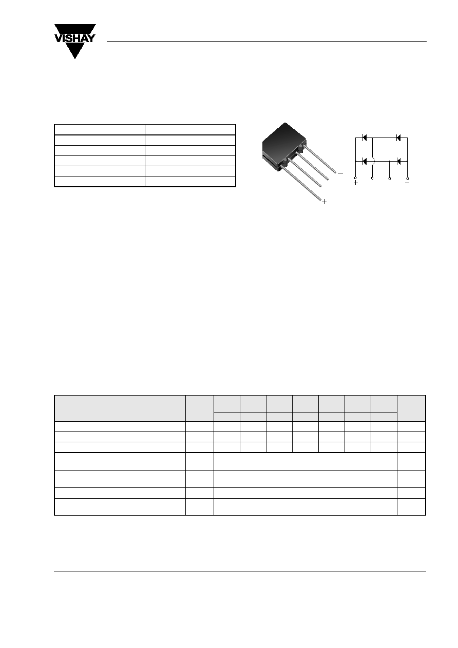
Case Style KBPM
~
~
~
~
Glass Passivated Single-Phase Bridge Rectifier
Major Ratings and Characteristics
I
F(AV)
1.5 A
V
RRM
50 V to 1000 V
I
FSM
50 A
I
R
5 µA
V
F
1.0 V
T
j
max.
150 ∞C
Features
∑ UL Recognition file number E54214
∑ Ideal for printed circuit board
∑ High surge current capability
∑ High case dielectric strength
∑ Meets MSL level 1, per J-STD-020C
Typical Applications
General purpose use in ac-to-dc bridge full wave rec-
tification for Switching Power Supply, Home Appli-
ances, Office Equipment, and Telecommunication
applications
Mechanical Data
Case: KBPM
Epoxy meets UL-94V-0 Flammability rating
Terminals: Silver plated (E4 Suffix) leads, solderable
per J-STD-002B and MIL-STD-750, Method 2026
Polarity: As marked on body
Maximum Ratings
Ratings at 25 ∞C ambient temperature unless otherwise specified.
Parameter
Symbol
KBP
005M
KBP
01M
KBP
02M
KBP
04M
KBP
06M
KBP
08M
KBP
10M
Unit
3N246
3N247
3N248
3N249
3N250
3N251
3N252
* Maximum repetitive peak reverse voltage
V
RRM
50 100 200 400 600 800 1000 V
* Maximum RMS voltage
V
RMS
35 70 140 280 420 560 700 V
* Maximum DC blocking voltage
V
DC
50 100 200 400 600 800 1000 V
Max. average forward output rectified current
at T
A
= 40 ∞C
I
F(AV)
1.5
A
* Peak forward surge current single half sine-
wave superimposed on rated load
I
FSM
50
30
A
Rating for fusing (t < 8.3 ms)
I
2
t
10
A
2
sec
* Operating junction and storage temperature
range
T
J
, T
STG
- 55 to + 150
∞C

www.vishay.com
2
Document Number 88531
03-Dec-04
KBP005M thru KBP10M, 3N246 thru 3N252
Vishay Semiconductors
Electrical Characteristics
Ratings at 25 ∞C ambient temperature unless otherwise specified.
Thermal Characteristics
Ratings at 25 ∞C ambient temperature unless otherwise specified.
Notes:
(1) Thermal resistance from junction to ambient and from junction to lead mounted on P.C.B. with, 0.47 x 0.47" (12 x12 mm) copper pads.
* JEDEC registered values
Ratings and Characteristics Curves
(T
A
= 25
∞C unless otherwise noted)
Parameter
Test condition
Symbol
KBP
005M
KBP
01M
KBP
02M
KBP
04M
KBP
06M
KBP
08M
KBP
10M
Unit
3N246
3N247
3N248
3N249
3N250
3N251
3N252
* Maximum instantaneous
forward voltage drop per leg
at 1.0 A
at 1.57 A
V
F
1.0
1.3
V
* Maximum DC reverse
current at rated DC blocking
voltage per leg
T
A
= 25 ∞C
T
A
= 125 ∞C
I
R
5.0
500
µA
Typical junction capacitance
per leg
at 4.0 V, 1 MHz
C
J
15
pF
Parameter
Symbol
KBP
005M
KBP
01M
KBP
02M
KBP
04M
KBP
06M
KBP
08M
KBP
10M
Unit
3N246
3N247
3N248
3N249
3N250
3N251
3N252
Typical thermal resistance per leg
(1)
R
JA
R
JL
40
13
∞C/W
Figure 1. Derating Curve Output Rectified Current
0
Bridge
Output
Full
W
ave
Rectified
Current,
A
verage
Amperes
Ambient Temperature ( ∞C)
20
40
60
80
100
120
140 150
0.2
0.4
0.6
0.8
1.0
1.2
1.4
1.6
60H
Z
Resistive or
Inductive Load
P.C.B. Mounted with
0.47 x 0.47" (12 x 12 mm)
Copper pads
Capacitive Load
Ipk/I
AV
= 5.0
Ipk/I
AV
= 10
Ipk/I
AV
= 20
(per leg)
Figure 2. Maximum Non-Repetitive Peak Forward Surge Current
Per Leg
0
1
10
100
Number of Cycles at 60 H
Z
10
20
30
40
50
60
Peak
Forward
Surge
Current
(A)
Single Half Sine-Wave
(JEDEC Method)
T
A
= 25 ∞C
T
J
= 150 ∞C
1.0 Cycle
KBP005M thru KBP10M, 3N246 thru 3N252
Document Number 88531
03-Dec-04
Vishay Semiconductors
www.vishay.com
3
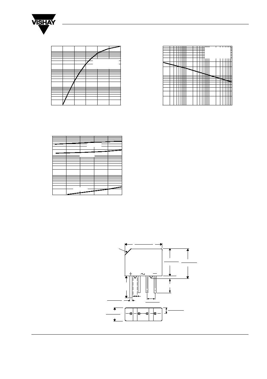
Package outline dimensions in inches (millimeters)
Figure 3. Typical Forward Characteristics Per Leg
Figure 4. Typical Reverse Leakage Characteristics Per Leg
0.4
0.6
0.8
1.0
1.2
1.4
1.6
Instantaneous Forward Voltage (V)
0.01
0.1
1
10
20
Instantaneous
Forward
Current
(A)
T
J
= 25 ∞C
Pulse Width = 300
µs
1% Duty Cycle
0
0.01
0.1
1
10
Instantaneous
Reverse
Current
(
µ
A)
60
80
100
20
40
Percent of Rated Peak Reverse Voltage (%)
T
J
= 25 ∞C
T
J
= 100 ∞C
T
J
= 125 ∞C
Figure 5. Typical Junction Capacitance Per Leg
1
0.1
10
100
Reverse Voltage (V)
1
10
100
Junction
Capacitance
(pF)
T
J
= 25 ∞C
f = 1.0 MH
Z
Vsig = 50mVp-p
0.125 x 45o
(3.2)
0.600 (15.24)
0.560 (14.22)
0.034 (0.86)
0.028 (0.76)
0.105 (2.67)
0.085 (2.16)
0.160 (4.1)
0.140 (3.6)
0.060
(1.52)
Polarity shown on front side of case: positive lead by beveled corner
0.460 (11.68)
0.50 (12.7) Min.
0.420 (10.67)
0.500 (12.70)
0.460 (11.68)
60
(15.2)
MIN.
DIA.
0.200 (5.08)
0.180 (4.57)
Case Style KBPM