
Document Number: 31015
Revision 05-Oct-05
www.vishay.com
16
CCF55, CCF60
Vishay Dale
For Technical Questions, contact ff3dresistors@vishay.com
Metal Film Resistors, Industrial,
±
1% Tolerance
FEATURES
∑ Power Ratings: 1/4, 1/2, 3/4 and 1 watt at + 70∞C
∑ ± 100ppm/∞C temperature coefficient
∑ Superior electrical performance
∑ Flame retardant epoxy conformal coating
∑ Standard 5 band color code marking for ease of
identification after mounting
∑ Tape and reel packaging for automatic insertion
(52.4mm inside tape spacing per EIA-296-E)
∑ Lead (Pb)-Free version is RoHS Compliant
GLOBAL
HISTORICAL
POWER RATING
LIMITING ELEMENT
TEMPERATURE
TOLERANCE
RESISTANCE
E-SERIES
MODEL
MODEL
P
70∞C
VOLTAGE MAX.
COEFFICIENT
RANGE
W
V
ppm/
∞
C
%
CCF55
CCF-55
0.25 / 0.5
250
± 100
± 1
10R - 3.01M
96
CCF60
CCF-60
0.50 / 0.75 / 1.0
500
± 100
± 1
10R - 1M
96
STANDARD ELECTRICAL SPECIFICATIONS
PARAMETER
UNIT
CCF55
CCF60
Rated Dissipation at 70∞C
W
0.25 / 0.5
0.5 / 0.75 / 1.0
Maximum Working Voltage
V
250
500
Insulation Voltage (1min)
V
eff
500
500
Dielectric Strength
VAC
450
450
Insulation Resistance
10
11
10
11
Operating Temperature Range
∞C
-65 / +165
-65 / +165
Terminal Strength (pull test)
lb
2
2
Weight
g
0.35 max
0.75 max
TECHNICAL SPECIFICATIONS
GLOBAL MODEL
RESISTANCE VALUE
TOLERANCE TEMPERATURE
PACKAGING
SPECIAL
CODE
COEFFICIENT
CCF55
R = Decimal
F =
± 1%
K = 100ppm
E36 = Lead (Pb)-Free, T/R (5000 pcs)
Blank = Standard
CCF60
K = Thousand
R36 = Tin/Lead, T/R (5000 pcs)
(Dash Number)
M = Million
(up to 3 digits)
10R0 = 10
From 1-999
680K = 680K
as applicable
1M00 = 1.0M
GLOBAL PART NUMBER INFORMATION
New Global Part Numbering: CCF55301RFKR36 (preferred part numbering format)
C
C
F
5
5
3
0
1
R
F
K
R
3
6
Historical Part Number example: CCF-553010F (will continue to be accepted)
CCF-55
3010
F
R36
HISTORICAL MODEL
RESISTANCE VALUE
TOLERANCE CODE
PACKAGING
Available
Pb-free
RoHS*
COMPLIANT
e3
* Pb containing terminations are not RoHs compliant, exemptions may apply
www.vishay.com
17
CCF55, CCF60
Vishay Dale
Document Number: 31015
Revision 05-Oct-05
For Technical Questions, contact ff3dresistors@vishay.com
* Test Methods per MIL-STD-202G/IEC 60115/DIN EN 140000 (as applicable).
GLOBAL
MODEL
CCF55
(Sn/Pb)
CCF55
(Sn)
PERFORMANCE
POWER RATING @ + 70
∞
C
CCF55
1/4 watt
1/2 watt
CCF60
1/2 watt
3/4 watt and 1 watt
TEST*
MAXIMUM
R
MAXIMUM
R
Thermal Shock
± 0.5%
-
Short Time Overload
± 0.5%
-
Low Temperature Operation
± 0.5%
-
Moisture Resistance
± 1.5%
-
Resistance to Soldering Heat
± 0.5%
-
Shock / Bump
± 0.5%
-
Vibration
± 0.5%
-
Life
± 0.5%
± 1.0%
Terminal Strength
± 0.2%
-
Dielectric Withstanding Voltage
± 0.5%
-
A
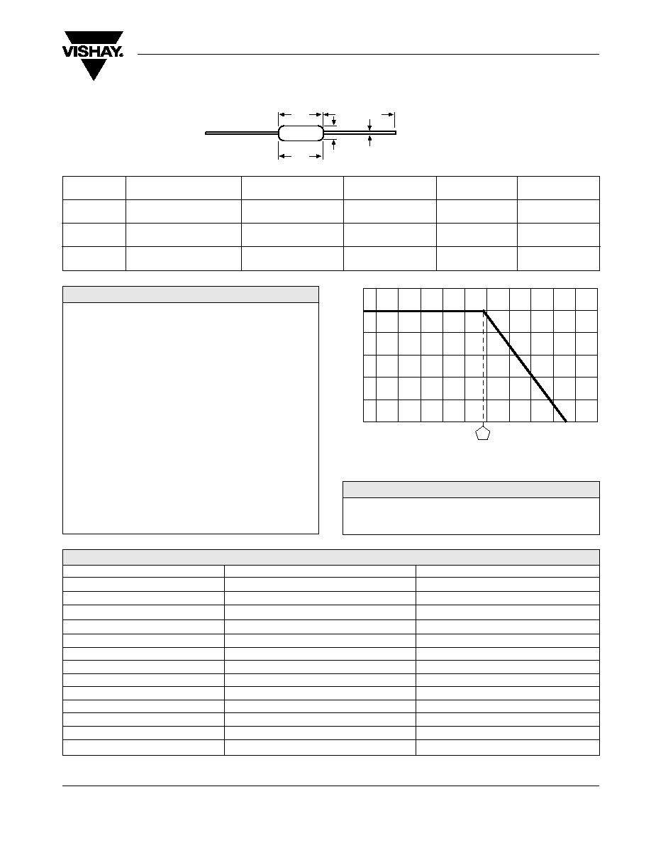
0.245 ± 0.020
[6.22 ± 0.51]
0.245 ± 0.020
[6.22 ± 0.51]
B
0.090 ± 0.008
[2.29 ± 0.20]
0.090 ± 0.008
[2.29 ± 0.20]
C
(Max.)
0.265
[6.73]
0.265
[6.73]
D
0.025 ± 0.002
[0.64 ± 0.05]
0.023 ± 0.002
[0.60 ± 0.05]
E
1.100 ± 0.040
[27.94 ± 1.02]
1.100 ± 0.040
[27.94 ± 1.02]
DIMENSIONS
in inches [millimeters]
Metal Film Resistors, Industrial, ± 1% Tolerance
D
B
A
E
C
Max.
Vishay Dale Models CCF55 and CCF60 are available in the
standard 96 resistance values per decade. Values are obtained
from the following decade table by multiplying by powers of 10.
As an example: 30.1 can represent 30.1 ohm, 301 ohm, 3.01
kohm, 30.1 kohm or 301 kohm.
10.0
10.2
10.5
10.7
11.0
11.3
11.5
11.8
12.1
12.4
12.7
13.0
13.3
13.7
14.0
14.3
14.7
15.0
15.4
15.8
16.2
16.5
16.9
17.4
17.8
18.2
18.7
19.1
19.6
20.0
20.5
21.0
21.5
22.1
22.6
23.2
23.7
24.3
24.9
25.5
26.1
26.7
27.4
28.0
28.7
29.4
30.1
30.9
31.6
32.4
33.2
34.0
34.8
35.7
36.5
37.4
38.3
39.2
40.2
41.2
42.2
43.2
44.2
45.3
46.4
47.5
48.7
49.9
51.1
52.3
53.6
54.9
56.2
57.6
59.0
60.4
61.9
63.4
64.9
66.5
68.1
69.8
71.5
73.2
75.0
76.8
78.7
80.6
82.5
84.5
86.6
88.7
90.9
93.1
95.3
97.6
-- Color band
MARKING
-65 -50 -25
0
25
50 70 75 100 125 150 165 175 200
AMBIENT TEMPERATURE IN ∞C
DERATING
RA
TED POWER IN %
RESISTANCE VALUES
0
20
40
60
80
100
120
0.344 ± 0.031
[8.74 ± 0.79]
0.139 ± 0.009
[3.53 ± 0.23]
0.400
[10.16]
0.025 ± 0.002
[0.64 ± 0.05]
1.000 ± 0.040
[25.40 ± 1.02]
CCF60