
Thick Film, Rectangular Chip Resistors
D...-CRCW
Vishay
www.vishay.com
For technical questions in Europe, contact: ff1aresistors@vishay.com
Document Number: 20008
78
For technical questions in Americas/Asia, contact: ff2bresistors@vishay.com
Revision: 04-Oct-06
FEATURES
∑ Metal glaze on high quality ceramic
∑ Protective overglaze
∑ Lead bearing (90 % Sn/10 % Pb) solder contacts
∑ Excellent stability (|
R/R
|
± 0.5 % for 1000 h at 70 ∞C) in
different environmental conditions
∑ High volume product suitable for commercial and special
applications
STANDARD ELECTRICAL SPECIFICATIONS
MODEL
SIZE
POWER RATING
P
70 ∞C
W
LIMITING
ELEMENT
VOLTAGE
MAX V
TEMPERATURE
COEFFICIENT
ppm/K
TOLERANCE
%
RESISTANCE
RANGE
E-SERIES
INCH
METRIC
CECC 40401-802/EIA-575
D10
CRCW0402
0402
1005
0.063
50
± 200
1)
± 100
± 200
± 1
± 1
± 5
1R0 - 9R76
10R - 10M
1R0 - 10M
24 + 96
24 + 96
24
Zero-Ohm-Resistor:
R
max
= 20 m
,
I
max
= 1 A
D11
CRCW0603
0603
1608
0.10
75
± 200
1)
± 100
± 200
± 1
± 1
± 5
1R0 - 9R76
10R - 10M
1R0 - 10M
24 + 96
24 + 96
24
Zero-Ohm-Resistor:
R
max
= 20 m
,
I
max
= 1.5 A
D12
CRCW0805
0805
2012
0.125
150
± 200
1)
± 100
± 200
± 1
± 1
± 5
1R0 - 9R76
10R - 10M
1R0 - 10M
24 + 96
24 + 96
24
Zero-Ohm-Resistor:
R
max
= 20 m
,
I
max
= 2 A
D25
CRCW1206
1206
3216
0.25
200
± 200
1)
± 100
± 200
± 1
± 1
± 5
1R0 - 9R76
10R - 10M
1R0 - 10M
24 + 96
24 + 96
24
Zero-Ohm-Resistor:
R
max
= 20 m
,
I
max
= 2.5 A
CRCW1210
1210
3225
0.33
200
± 200
1)
± 100
± 200
± 1
± 1
± 5
1R0 - 9R76
10R - 1M0
1R0 - 10M
24 + 96
24 + 96
24
Zero-Ohm-Resistor:
R
max
= 20 m
,
I
max
= 2.5 A
CRCW1218
1218
3246
1.0
200
± 200
1)
± 100
± 200
± 1
± 1
± 5
1R0 - 9R76
10R - 2M2
1R0 - 2M2
24 + 96
24 + 96
24
Zero-Ohm-Resistor:
R
max
= 20 m
,
I
max
= 4 A
CRCW2010
2010
5025
0.5
400
± 200
1)
± 100
± 200
± 1
± 1
± 5
1R0 - 9R76
10R - 10M
1R0 - 10M
24 + 96
24 + 96
24
Zero-Ohm-Resistor:
R
max
= 20 m
,
I
max
= 3 A
CRCW2512
2512
6332
1.0
500
± 200
1)
± 100
± 200
± 1
± 1
± 5
1R0 - 9R76
10R - 10M
1R0 - 10M
24 + 96
24 + 96
24
Zero-Ohm-Resistor:
R
max
= 20 m
,
I
max
= 4 A
1)
100 ppm/K on request
∑ Ask about further value ranges
∑ For low values see Thick Film rectangular low value resistors
∑ For high values see Thick Film rectangular high values
∑ Marking and packaging: see appropriate catalog or web pages
∑ For precision Thick Film CRCW see Thick Film rectangular
Precision Resistors
∑ Power rating depends on the max. temperature at the solder point,
the component placement density and the substrate material
∑ AgPd or Pd terminations for conductive adhesive attachment on
request
1)
Measuring conditions in acc. to CECC 4040
2)
Rated voltage:
3)
Depending on solder pad dimensions
TECHNICAL SPECIFICATIONS
PARAMETER
UNIT
D10
CRCW0402
D11
CRCW0603
D12
CRCW0805
D25
CRCW1206
CRCW1210 CRCW1218 CRCW2010 CRCW2512
Rated Dissipation at 70 ∞C
(CECC 40401 | EIA 575)
W
0.063
0.10
0.125
0.25
0.33
1.0
0.5
1.0
Limiting Element Voltage
2)
V
50
75
150
200
200
200
400
500
Insulation Voltage (1 min)
V
peak
> 75
> 100
> 200
> 300
> 300
> 300
> 300
> 300
Thermal Resistance
K/W
870
1)
550
1)
440
1)
220
1)
140
3)
65
3)
88
3)
65
3)
Insulation Resistance
Category Temperature
∞C
Failure Rate
h
-1
0.3 ◊ 10
-9
Weight/1000 pcs
g
0.65
2
5.5
10
16
29.5
25.5
40.5
P
x
R

D...-CRCW
Thick Film, Rectangular Chip Resistors
Vishay
Document Number: 20008
For technical questions in Europe, contact: ff1aresistors@vishay.com
www.vishay.com
Revision: 04-Oct-06
For technical questions in Americas/Asia, contact: ff2bresistors@vishay.com
79
DIMENSIONS
SIZE
DIMENSIONS [in millimeters]
INCH METRIC
L
W
H
T1
T2
0402
1005
1.0 ± 0.05 0.5 ± 0.05 0.35 ± 0.05 0.25 ± 0.05
0.2 ± 0.1
0603
1608
1.55
+ 0.10
-
0.05
0.85 ± 0.1 0.45 ± 0.05
0.3 ± 0.2
0.3 ± 0.2
0805
2012
2.0
+ 0.20
-
0.10
1.25 ± 0.15 0.45 ± 0.05
0.3
+ 0.20
-
0.10
0.3 ± 0.2
1206
3216
3.2
+ 0.10
-
0.20
1.6 ± 0.15 0.55 ± 0.05
0.45 ± 0.2
0.4 ± 0.2
1210
3225
3.2 ± 0.2
2.5 ± 0.2
0.55 ± 0.05
0.45 ± 0.2
0.4 ± 0.2
1218
3246
3.2
+ 0.10
-
0.20
4.6 ± 0.15 0.55 ± 0.05
0.45 ± 0.2
0.4 ± 0.2
2010
5025
5.0 ± 0.15 2.5 ± 0.15
0.6 ± 0.1
0.6 ± 0.2
0.6 ± 0.2
2512
6332
6.3 ± 0.2
3.15 ± 0.15
0.6 ± 0.1
0.6 ± 0.2
0.6 ± 0.2
SIZE
SOLDER PAD DIMENSIONS [in millimeters]
REFLOW SOLDERING WAVE SOLDERING
INCH
METRIC
a
b
l
a
b
l
0402
1005
0.4
0.6
0.5
0603
1608
0.5
0.9
1.0
0.9
0.9
1.0
0805
2012
0.7
1.3
1.2
0.9
1.3
1.3
1206
3216
0.9
1.7
2.0
1.1
1.7
2.3
1210
3225
0.9
2.5
2.0
1.1
2.5
2.2
1218
3246
1.05
4.9
1.9
1.25
4.8
1.9
2010
5025
1.0
2.5
3.9
1.2
2.5
3.9
2512
6332
1.0
3.2
5.2
1.2
3.2
5.2
C
R
C W
0
8
5
0
5 6 2 R F K T A
PA RT NUMBER AND PRODUCT DESCRIPTION
1)
MODEL/SIZE
VALUE TOLERANCE
T.C.R.
PACKAGING
2)
SPECIAL
D100402
3 digit value
1 digit multiplier
F = ± 1 %
B = ± 100 ppm/K
up to 2 digits
D110603
A = ± 200 ppm/K
D120805
D251206
P ART NUMBER: D1208050B5620FP0
PRODUCT DESCRIPTION: D12 100 562R 1 % P5
D12
100 562R
1 %
P5
MODEL
RESIST ANCE V ALUE TOLERANCE
PACKAGING
2)
± 200 ppm/K
49K9 = 49.9 k
D10
± 100 ppm/K
D11
D12
D25
5R1 = 5.1
0R0 = Jumper
TCR
SPECIAL CHARACTER
0 = neutral
MULTIPLIER
7 = *10
-3
8 = *10
-2
9 = *10
-1
0 = *10
0
1 = *10
1
0000 = Jumper
2 = *10
2
3 = *10
3
4 = *10
4
5 = *10
5
6 = *10
6
MODEL/SIZE
VALUE TOLERANCE
PACKAGING
2)
SPECIAL
R = Decimal
F = ± 1 %
J = ± 5 %
Z = Zero Ohm Jumper
up to 2 digits
TR = Customer Trimmable
K = Thousand
TA = RT1
TB = RT5
TC = RT6
TD = RT7
TF = R02
TG = R67
TH = R82
TK = RT9
BA = B27
M = Million
P ART NUMBER: CRCW0805562RFKTA
P RODUCT DESCRIPTION: CRCW 0805 5620 F 100 RT1
CRCW
5620 F 100
RT1
MODEL
RESISTANCE VALUE TOLERANCE
PACKAGING
2)
CRCW
±
100 ppm/K
685 = 6.8 M
224 = 220 k
±
200 ppm/K
0000 = Jumper
K = ± 100 ppm/K
N = ± 200 ppm/K
S = Jumper or Special
T.C.R.
RT1
RT5
RT6
RT7
R02
R67
R82
RT9
B27
± 1 %
± 5 %
0 = Jumper
CRCW0402
CRCW0603
CRCW0805
CRCW1206
CRCW1210
CRCW2010
CRCW2512
CRCW2512
J = ± 5 %
M0
PZ
B5
BN
P0
P5
PN
MZ
MU
M0
PZ
B5
BN
0805
0402
0603
0805
1206
SIZE
F = ± 1 %
J = ± 5 %
Z = Zero Ohm Jumper
1201
1218
2010
2512
± 1 % = 3 sig.digits, plus multiplier
± 5 % = 2 sig.digits, plus multiplier
D25
D25
T.C.R.
P0
P5
PN
MZ
MU
D 1 2 0 8 0
0
5 B
5
6
2
0
F
P
0
Note
1.
Preferred way for ordering products is by use of the PART NUMBER.
2.
Please refer to table PACKAGING, page 80.
www.vishay.com
For technical questions in Europe, contact: ff1aresistors@vishay.com
Document Number: 20008
80
For technical questions in Americas/Asia, contact: ff2bresistors@vishay.com
Revision: 04-Oct-06
D...-CRCW
Vishay
Thick Film, Rectangular Chip Resistors
1)
On request
2)
European/N.American packaging codes: na = NOT AVAILABLE
∑ Further information about packaging: see appropriate catalog or web page.
PACKAGING
MODEL
REEL
BULK
TAPE WIDTH
DIAMETER
PIECES/REEL
PITCH
PACKAGING CODE
BULK FEEDING MAGAZINE
PAPER
1)
BLISTER
2)
PIECES
1)
CODE
2)
D10
CRCW0402
8 mm
180 mm/7"
10 000
2 mm
P0/TD
50 000
MZ/BA
330 mm/13"
50 000
2 mm
PZ/TE
D11
CRCW0603
8 mm
180 mm/7"
5000
4 mm
P5/TA
B5/na
25 000
MU/BA
255 mm/10"
10 000
4 mm
P0/TB
330 mm/13"
20 000
4 mm
PN/TC
BN/na
D12
CRCW0805
8 mm
180 mm/7"
5000
4 mm
P5/TA
B5/na
10 000
MO/BA
255 mm/10"
10 000
4 mm
P0/TB
330 mm/13"
20 000
4 mm
PN/TC
BN/na
D25
CRCW1206
8 mm
180 mm/7"
5000
4 mm
P5/TA
B5/na
255 mm/10"
10 000
4 mm
P0/TB
330 mm/13"
20 000
4 mm
PN/TC
BN/na
CRCW1210
8 mm
180 mm/7"
5000
4 mm
P5/TA
B5/RG1
330 mm/13"
20 000
4 mm
PN/TC
BN/na
CRCW1218
12 mm
180 mm/7"
4000
4 mm
TK
CRCW2010
12 mm
180 mm/7"
4000
4 mm
TF
CRCW2512
12 mm
180 mm/7"
2000
8 mm
B2/TG
4000
4 mm
TH
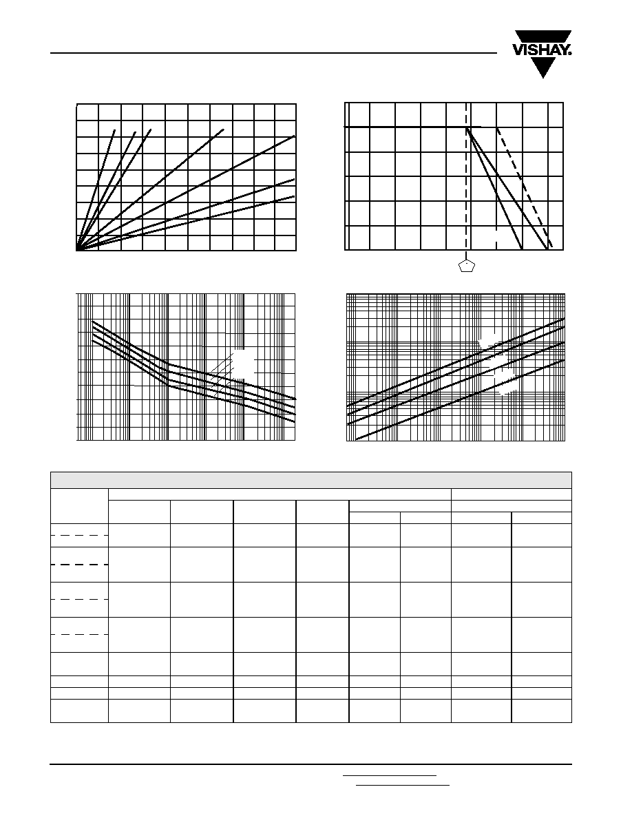
0402
0603 0805
1206
1210
2010
2512
90
80
70
60
50
40
30
20
10
0
0
0.1
0.2
0.3
0.4
0.5
Power in Watts
T
e
mperature Rise in
∞
C
Temperature Rise
1218
Derating
* There are differences in board layout and measurements between CECC and EIA.
- 55
- 25
0
25
50
75
100
125
150 175
120
100
80
60
40
20
0
Ambient Temperature in
∞C
70
Rated Power in
%
EIA*
CECC*
100
1K
10K
100K
1M
10M
Non-Linearity
110
100
90
80
70
60
50
40
30
20
10
Resistance Value in
Non-Linearity A
3
in dB
1206
0805
0603
0402
100
1K
10K
100K
1M
10M
100
10
1
0.1
Current Noise
Resistance Value in
Current Noise in µ
V
/V
0402
0603
0805
1206

D...-CRCW
Thick Film, Rectangular Chip Resistors
Vishay
Document Number: 20008
For technical questions in Europe, contact: ff1aresistors@vishay.com
www.vishay.com
Revision: 04-Oct-06
For technical questions in Americas/Asia, contact: ff2bresistors@vishay.com
81
140
120
100
80
60
40
20
0
20 40 60 80 100 120 140 160 180
Load in W
0.01
0.1
1
20 40 60 80 100 120 140 160
180
Film temperature
s in ∞ C
0.01
0.1
1
10 1 0.1 0.01
Resistance change
R/R %
R/R (t) = f [R/R (t = 1000 h)]
Parameter : time
0.5 0.4 0.3 0.2 0.1 0
140
120
100
80
60
40
20
0
Film temperature
s in ∞ C
Stability nomogram typical values (for handling see general explanations)
Resistance chan
g
e
[
R
/
R
] in
%
after 1000 h
Temperature rise in
¸
∞C
¸
= 20
∞ C
40
∞ C
60
∞ C
80
∞ C
100 ∞
C
12
0 ∞
C
140
∞
C
t =
100
000
h
10
000
h
500
0 h
20
00
h
10
00
h
R/R [t = 1000 h] = f [s]
Parameter: resistance value
D25 -
CRCW
1206
¸
= f [P]
Parameter : size
D12 - CRCW
08
05
D1
1 - CRCW0603
D
1
0
-
CR
CW
0
4
02
¸ = f [s]
Parameter:
u
1
M
10
K
10
M
0.25 W
0.125 W
0.0625 W
120
100
80
60
40
20
1
2 3 5 7 10
2 3 5 7 100 2 3 5 7
60
80
100
120
140
surface temperature
s [∞C]
number of mounted resistors [pcs]
Power rating as a function of packaging density (guideline)
u
= 120
∞
C
u
= 100
∞ C
u
=
80 ∞
C
u
= 60
∞
C
u
= 40
∞
C
u
= 20
∞
C
¸
=
[
∞C
]
www.vishay.com
For technical questions in Europe, contact: ff1aresistors@vishay.com
Document Number: 20008
82
For technical questions in Americas/Asia, contact: ff2bresistors@vishay.com
Revision: 04-Oct-06
D...-CRCW
Vishay
Thick Film, Rectangular Chip Resistors
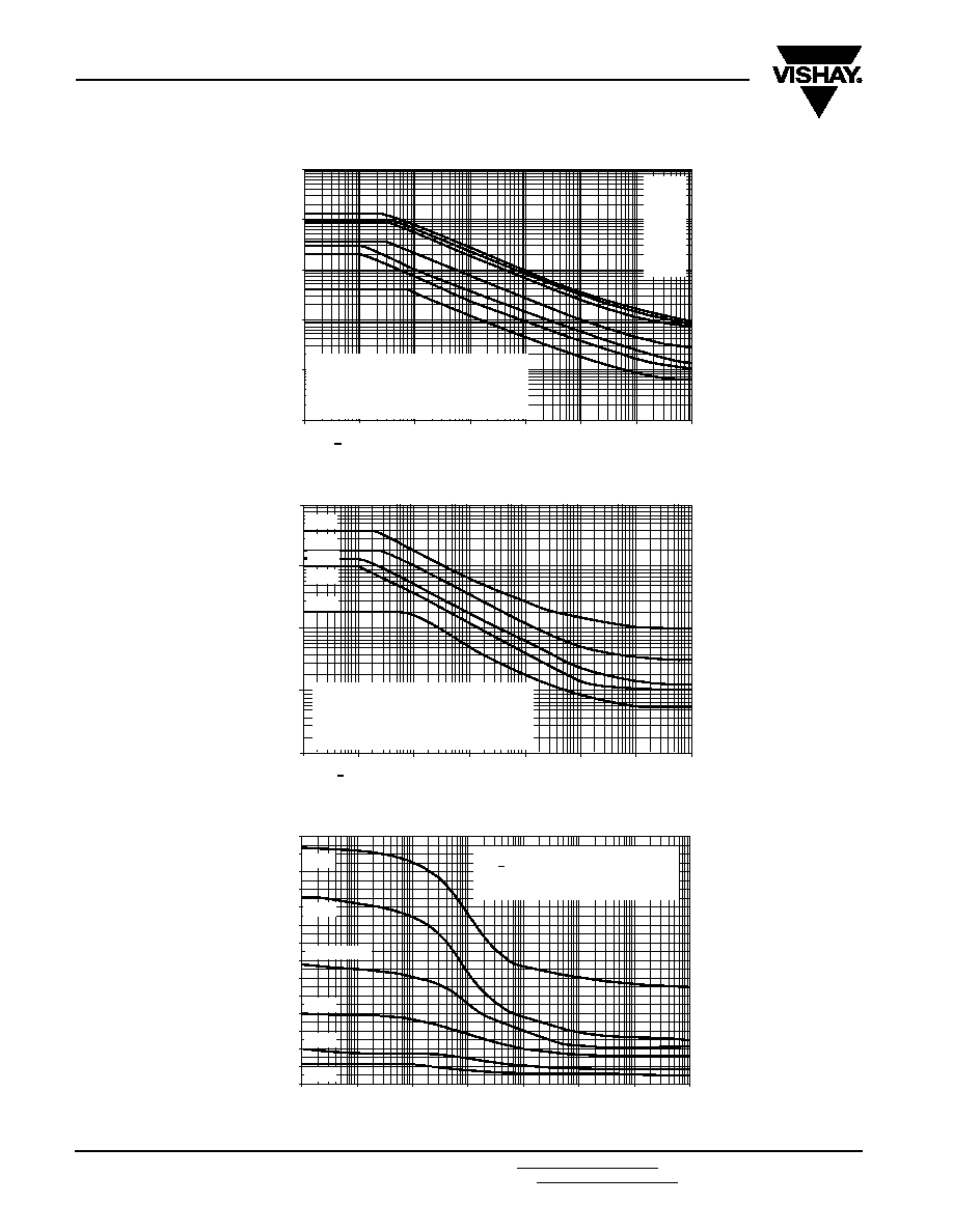
1000
100
10
1
0.1
0.01
10
-6
10
-5
10
-4
10
-3
10
-2
10
-1
1
10
2512
1218
2010
1206
0805
0603
0402
Secondary Conditions:
a) P
P (peak pulse, single pulse)
b)
u
< 70
∞
c) ˚ see diagram (max. pulse voltage)
Square Pulse in t
j
s
Pulse Rating P
0
Power Ratin
g
P
in W
atts
100
10
1
0.10
0.01
10
-6
10
-5
10
-4
10
-3
10
-2
10
-1
1
10
Secondary Conditions:
a) P
P (permissible constant power
at + 70
∞ C)
b)
u
< 70
∞
c) ˚ see diagram (max. pulse voltage)
Square Pulse in t
j
s
Pulse Rating P
P
70
Power Ratin
g
P
in W
atts
1218
1218
1206
0805
0603
0402
0
1200
800
500
100
10
-6
10
-5
10
-4
10
-3
10
-2
10
-1
1
10
Square Pulse in t
j
s
Maximum Pulse Voltage
Pulse V
olta
g
e
˚
max
in V
2512
1206/1218
2010
0805
Secondary Conditions:
a) P see diagrams (Pulse Rating)
b)
u
< 70
∞
0603
0402
1400
1300
1100
1000
900
700
600
400
300
200
D...-CRCW
Thick Film, Rectangular Chip Resistors
Vishay
Document Number: 20008
For technical questions in Europe, contact: ff1aresistors@vishay.com
www.vishay.com
Revision: 04-Oct-06
For technical questions in Americas/Asia, contact: ff2bresistors@vishay.com
83
1)
Limits for change of resistance at test acc. to CECC
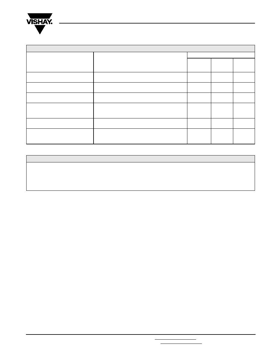
PERFORMANCE
TEST
CONDITIONS OF TEST
REQUIREMENTS IN %
1)
0402
0603
0805
1206
1210
1218
2010
2512
Endurance Test at 70 ∞C
IEC 60115-1 4.25.1; EIA-575
1000 hours at 70 ∞C, 1.5 hours "ON", 0.5 hours "OFF"
± 1.0
± 0.5
± 1.0
Endurance at UCT
IEC 60115-1 4.25.3
1000 hours at 125 ∞C without load
± 1.0
± 0.5
± 1.0
Overload Test
IEC 60115-1 4.13; EIA-575
Short time overload, 2.5 x rated voltage or 2 x limiting
element voltage.
± 0.25
± 0.25
± 0.5
Thermal Shock
IEC 60115-1 4.19; IEC 60068-2-14;
EIA-575
Rapid change between upper and lower category
temperature
± 0.25
± 0.25
± 0.5
Damp Heat Steady State
IEC 60115-1 4.24; IEC 60068-2-3
56 days at 40 ∞C and 93 % relative humidity
± 1.0
± 0.5
± 1.0
Resistance to Soldering Heat
IEC 60115-1 4.18; IEC 60068-2-20;
EIA-575
10 seconds at 260 ∞C solder bath temperature
± 0.25
± 0.25
± 0.5
APPLICABLE SPECIFICATIONS
∑
CECC40000/40400/40401-004,-006,-007,-802
∑ EN140400/IEC 60115-1
∑ EIA-575

Legal Disclaimer Notice
Vishay
Document Number: 91000
www.vishay.com
Revision: 08-Apr-05
1
Notice
Specifications of the products displayed herein are subject to change without notice. Vishay Intertechnology, Inc.,
or anyone on its behalf, assumes no responsibility or liability for any errors or inaccuracies.
Information contained herein is intended to provide a product description only. No license, express or implied, by
estoppel or otherwise, to any intellectual property rights is granted by this document. Except as provided in Vishay's
terms and conditions of sale for such products, Vishay assumes no liability whatsoever, and disclaims any express
or implied warranty, relating to sale and/or use of Vishay products including liability or warranties relating to fitness
for a particular purpose, merchantability, or infringement of any patent, copyright, or other intellectual property right.
The products shown herein are not designed for use in medical, life-saving, or life-sustaining applications.
Customers using or selling these products for use in such applications do so at their own risk and agree to fully
indemnify Vishay for any damages resulting from such improper use or sale.