ESS, ESW, ESN, EGS, EGW, EGN
Vishay Dale
www.vishay.com
126
Document Number 30203
Revision 23-Sep-02
For technical questions, contact ww2bresistors@vishay.com
Wirewound Resistors, Military/Established Reliability
MIL-PRF-39007 Qualified, Type RWR, R Level
FEATURES
∑ High temperature silicone coated
∑ Complete welded construction
∑
Qualified to MIL-PRF-39007
∑
Available in non-inductive styles (types ESN and EGN) with
Aryton-Perry winding for lowest reactive components
∑ "S" level failure rate available
ORDERING INFORMATION
M
FAILURE
RATE
RWR74
MILITARY
TYPE
S
TERMINAL WIRE
AND WINDING
49R9
RESISTANCE
F
TOLERANCE
STANDARD ELECTRICAL SPECIFICATIONS
MIL-PRF-39007
POWER RATING
WEIGHT
P
25
∞
C
(Typical)
MODEL
TYPE
W
±
0.1%
±
0.5 &
±
1%
g
EGS-1-80
RWR81S
1
0.499 - 1k
0.1 - 1k
0.21
EGW-1
RWR81W
1
0.499 - 1k
0.1 - 1k
0.21
EGN-1-80
RWR81N
1
0.499 - 499
0.1 - 499
0.21
EGN-1-10
RWR81Z
1
0.499 - 499
0.1 - 499
0.21
EGS-2
RWR82S
1.5
0.499 - 1.3k
0.1 - 1.3k
0.23
EGW-2
RWR82W
1.5
0.499 - 1.3k
0.1 - 1.3k
0.23
EGN-2
RWR82N
1.5
0.499 - 649
0.1 - 649
0.23
EGN-2-10
RWR82Z
1.5
0.499 - 649
0.1 - 649
0.23
EGS-3-80
RWR80S
2
0.499 - 3.16k
0.1 - 3.16k
0.34
EGW-3
RWR80W
2
0.499 - 3.16k
0.1 - 3.16k
0.34
EGN-3-80
RWR80N
2
0.499 - 1.58k
0.1 - 1.58k
0.34
EGN-3-10
RWR80Z
2
0.499 - 1.58k
0.1 - 1.58k
0.34
ESS-2A
RWR71S
2
0.499 - 12.1k
0.1 - 12.1k
0.90
ESW-2A
RWR71W
2
0.499 - 12.1k
0.1 - 12.1k
0.90
ESN-2A
RWR71N
2
0.499 - 6.04k
0.1 - 6.04k
0.90
ESN-2A-10
RWR71Z
2
0.499- 6.04k
0.1 - 6.04k
0.90
ESS-2B
RWR89S
3
0.499 - 4.12k
0.1 - 4.12k
0.70
ESW-2B
RWR89W
3
0.499 - 4.12k
0.1 - 4.12k
0.70
ESN-2B
RWR89N
3
0.499 - 2.05k
0.1 - 2.05k
0.70
ESN-2B-10
RWR89Z
3
0.499 - 2.05k
0.1 - 2.05k
0.70
ESS-5
RWR74S
5
0.499 - 12.1k
0.1 - 12.1k
4.2
ESW-5
RWR74W
5
0.499 - 12.1k
0.1 - 12.1k
4.2
ESN-5
RWR74N
5
0.499 - 6.04k
0.1 - 6.04k
4.2
ESN-5-10
RWR74Z
5
0.499 - 6.04k
0.1 - 6.04k
4.2
EGS-10-80
RWR84S
7
0.499 - 12.4k
0.1 - 12.4k
3.6
EGW-10
RWR84W
7
0.499 - 12.4k
0.1 - 12.4k
3.6
EGN-10-80
RWR84N
7
0.499- 6.19k
0.1 - 6.19k
3.6
EGN-10-10
RWR84Z
7
0.499- 6.19k
0.1 - 6.19k
3.6
ESS-10
RWR78S
10
0.499 - 39.2k
0.1 - 39.2k
9.0
ESW-10
RWR78W
10
0.499 - 39.2k
0.1 - 39.2k
9.0
ESN-10
RWR78N
10
0.499- 19.6k
0.1 - 19.6k
9.0
ESN-10-10
RWR78Z
10
0.499- 19.6k
0.1 - 19.6k
9.0
MILITARY RANGE
www.vishay.com
127
ESS, ESW, ESN, EGS, EGW, EGN
Vishay Dale
Document Number 30203
Revision 23-Sep-02
For technical questions, contact ww2bresistors@vishay.com
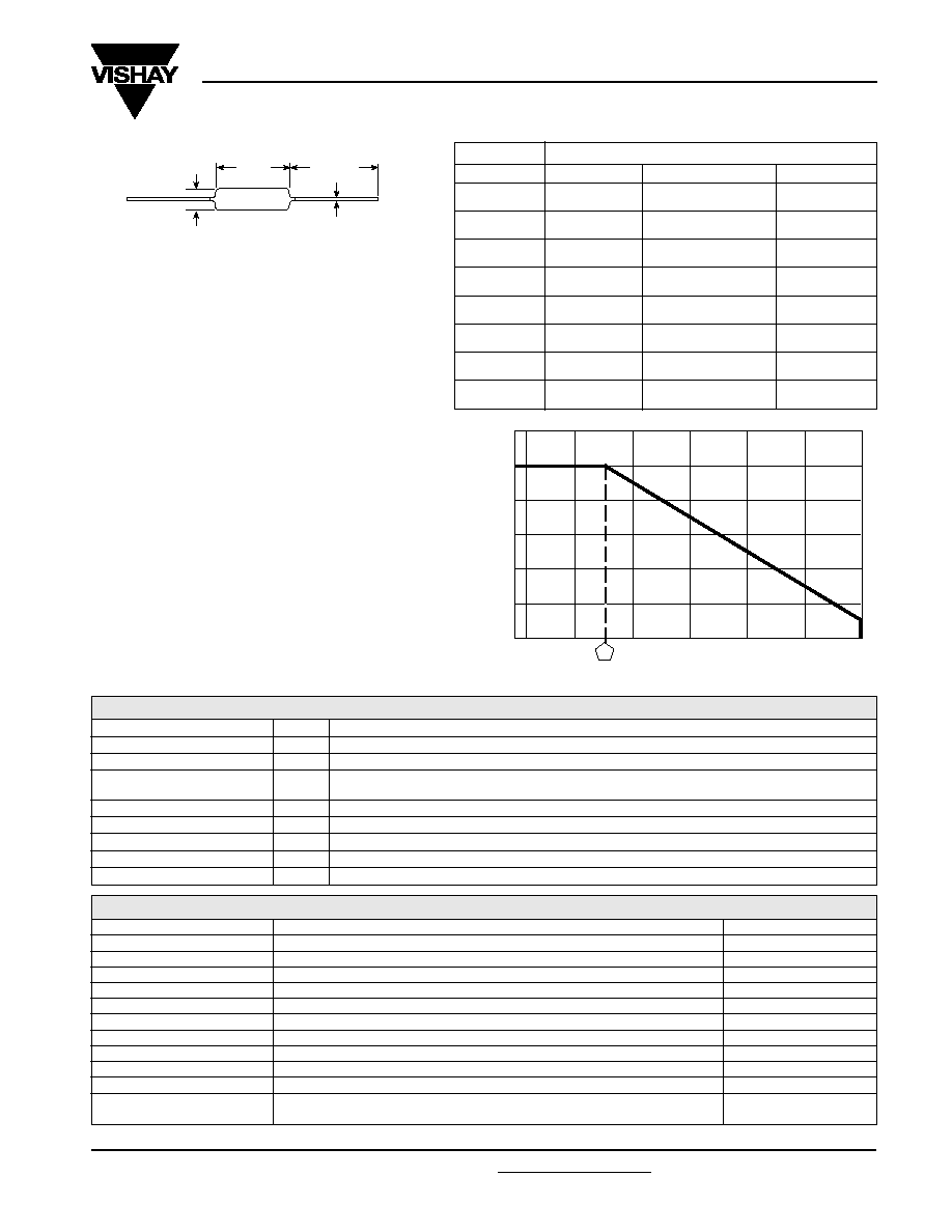
DIMENSIONS
B
1.50 [38.10]*
Min.
A
C
MIL-PRF-39007
DIMENSIONS -
in inches [millimeters]
MODEL
A
B
C
RWR81
0.250
±
0.031
.085
±
0.020
0.020
±
0.0015
[6.35
±
0.787]
[2.16
±
0.508]
[0.508
±
0.038]
RWR82
0.312
±
0.016
0.078 + 0.016 - 0.031
0.020
±
0.0015
[7.92
±
0.406]
[1.98 + 0.406 - 0.787]
[0.508
±
0.038]
RWR80
0.406
±
0.031
0.094
±
0.031
0.020
±
0.0015
[10.31
±
0.787]
[2.39
±
0.787]
[0.508
±
0.038]
RWR71
0.812
±
0.062
0.187
±
0.031
0.032
±
0.002
[20.62
±
1.58]
[4.75
±
0.787]
[0.813
±
0.051]
RWR89
0.560
±
0.062
0.187
±
0.031
0.032
±
0.002
[14.22
±
1.58]
[4.75
±
0.787]
[0.813
±
0.051]
RWR74
0.875
±
0.062
0.312
±
0.031
0.040
±
0.002
[22.23
±
1.58]
[7.92
±
0.787]
[1.02
±
0.051]
RWR84
0.875
±
0.062
0.312
±
0.031
0.040
±
0.002
[22.23
±
1.58]
[7.92
±
0.787]
[1.02
±
0.051]
RWR78
1.780
±
0.062
0.375
±
0.031
0.040
±
0.002
[45.21
±
1.58]
[9.53
±
0.787]
[1.02
±
0.051]
MATERIAL SPECIFICATIONS
Element:
Copper-nickel alloy or nickel-chrome alloy,
depending on resistance value
Core:
Ceramic, Beryllium oxide, steatite or alumina,
depending on power requirement
Coating:
Special high temperature silicone
Terminal and Winding:
The terminal and the winding
are identified by a letter symbol in the military type
designation. Military Symbol:
S
= Solderable, inductively wound
W
= Weldable, inductively wound
N
= Solderable, non-inductively wound
Z
= Weldable, non-inductively wound
Terminals:
Solderable - Tinned Copperweld
Æ
Weldable - Bare Nickel per MIL-STD-1276, Type N-1
End Caps:
Stainless Steel
Part Marking:
Source Code, JAN, Military PIN,
Date/Lot Code
APPLICABLE MIL-SPECIFICATION
MIL-PRF-39007:
This is the military specification
covering axial lead established reliability power
wirewound resistors.
Vishay Dale ESS, ESW, EGS, EGW, ESN and EGN
resistors meet or exceed the electrical, environmental
and dimensional requirements of this specification.
PERFORMANCE
TEST
CONDITIONS OF TEST
TEST LIMITS
Thermal Shock
MIL-STD-2.2, Method 303
±
(0.2% + 0.005
)
R
Short Time Overload
5 x rated power (RWR71, 80, 81, 89, 82), 10 x rated power (RWR74, 78, 84) for 5 seconds
±
(0.2% + 0.005
)
R
Dielectric Withstanding Voltage
500Vrms (RWR80, 81, 82), 1000Vrms (RWR71, 74, 78, 84, 89), 1 minute duration
±
(0.1% + 0.005
)
R
Low Temperature Storage
- 65
∞
C for 24 hours
±
(0.1% + 0.005
)
R
High Temperature Exposure
250
∞
C for 2000 hours
±
(1.0% + 0.005
)
R*
Moisture Resistance
MIL-STD-202, Method 106
±
(0.2% + 0.005
)
R
Shock, Specified Pulse
MIL-STD-202, Method 205, Condition C
±
(0.1% + 0.005
)
R
Vibration, High Frequency
MIL-STD-202, Method 204, Condition D
±
(0.1% + 0.005
)
R
Load Life
2000 hours at rated power, + 25
∞
C, 1.5 hours "ON", 0.5 hours "OFF"
±
(0.5% + 0.005
)
R
Extended Life
10,000 hours at rated power, + 25
∞
C, 1.5 hours "ON", 0.5 hours "OFF"
±
(1.0% + 0.005
)
R
MIL-STD-202, Method 211, Condition A and C
5 pound (RWR80, 81, 82), 10 pound (RWR71, 74, 78, 84, 89)
TECHNICAL SPECIFICATIONS
PARAMETER
UNIT
ESS, ESW, ESN, EGS, EGW, EGN RESISTOR CHARACTERISTICS
Temperature Coefficient
ppm/
∞
C
±
650 for 0.1
to 0.499
,
±
400 for 0.505
to 1
,
±
50 for 1.1
to 10
,
±
20 for 10
and above
Dielectric Withstanding Voltage
V
AC
500 minimum for 2 watt and smaller, 1000 minimum for 3 watt and larger
Short Time Overload
-
5 x rated power for 5 seconds for 3 watt size and smaller,
10 x rated power for 5 seconds for 5 watt size and greater
Maximum Working Voltage
V
(P x R)
1/2
Insulation Resistance
1000 Megohm minimum dry, 100 Megohm minimum after moisture test
Terminal Strength
lb
5 minimum for 2 watt and smaller, 10 minimum for 3 watt and larger
Solderability
-
Meets requirements of ANSI J-STD-002
Operating Temperature Range
∞
C
- 65/+ 250
Wirewound Resistors, Military/Established Reliability
MIL-PRF-39007 Qualified, Type RWR, R Level
*For resistance values above 100 ohms, Test Limit is
±
1.0%.
Terminal Strength
±
(0.1% + 0.005
)
R
*On some standard reel pack methods, the leads may be
trimmed to a shorter length than shown.
Derating
-65-50
0
50
150
250
AMBIENT TEMPERATURE IN
∞
C
RA
TED POWER IN %
25
0
20
40
60
80
100
120