F1710-305V
Vishay Roederstein
www.vishay.com
To contact us: RFI@Vishay.com
Document Number 27606
74
Revision 03-Oct-02
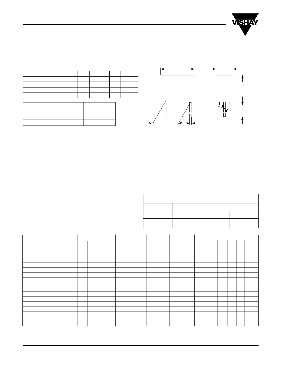
AC-Capacitors, Suppression Capacitors
Class Y2 (X1) AC 305V (MKT)
Dimensions in mm
L
X
ÿ d
W
±
0.4
H
pcm
±
0.4
LEAD LENGTH
ORDERING CODE**
(X)
Code
(see page 49 - Document No. 26511)
(mm)
Pos.11
1-4
5-7
8
9
10
11-13
4
-1
B
1710
. . .
.
3
.
B
.
0
6
-1
C
1710
. . .
.
3
.
C
.
0
15
-1
D
1710
. . .
.
3
.
D
.
0
30
+5
L
1710
. . .
.
3
.
L
.
0
REFERENCE STANDARDS:
EN/IEC 60068; IEC 60384-14/2 1993/07
UL 1414; CSA C22 2 No. 1-M 1994
DIELECTRIC:
Polyester film
ELECTRODES:
Metal evaporated
RATED VOLTAGE:
AC305V; 50/60Hz
PERMISSABLE DC VOLTAGE:
DC1000V
CAPACITANCE RANGE:
E12 series 1000pFY2 -0.1
µ
FY2(X1)
preferred values acc. to E6
CAPACITANCE TOLERANCE:
Standard
±
20%; on request
±
10% and
±
5%
TERMINALS:
Radial tinned copper wire
COATING:
Plastic case, epoxy resin sealed,
flame retardant; UL 94V-0
CLIMATIC TESTING CLASS ACC. TO
EN/IEC 60068-1:
40/100/56
pcm
Pitch Code
Terminal ÿd
(mm)
Pos. 10
(mm)
10
D
0.6
> 10
F, I or K
0.8
TEST VOLTAGE:
(Electrode/electrode): DC 5000V for 1 sec. at 25
∞
C;
Between interconnected terminations and case (foil method);
AC 2500V for 2 sec. at 25
∞
C
DISSIPATION FACTOR TAN
:
< 1% measured at 1kHz
INSULATION RESISTANCE:
30 G
average value
15 G
average value
CAPACITANCE
TOLERANCE
PITCH
BOX
DIMENSIONS
WEIGHT
QUANTITY
ORDERING CODE**
Code Pos 5-7
Code Pos 8
Code
NO
W x H x L
PACKAGE
(as class Y2
J =
±
5%
Pos. 10
(Lead Length (Lead Length
and X1)
K =
±
10%
6
-1
mm)
6
-1
mm)
M =
±
20%
(mm)
(mm)
+ 0.2 / - 0.4mm
(g)
(pcs)*
1-4
5-7
8
9
10
11-13
1000
pF
M
10.0
D
32
3.8 x 8.8 x 12.8
0.6
1500
1710
210
M
3
D
.
B0
1200
pF
M
10.0
D
32
3.8 x 8.8 x 12.8
0.6
1500
1710
212
M
3
D
.
B0
1500
pF
M
10.0
D
32
3.8 x 8.8 x 12.8
0.6
1500
1710
215
M
3
D
.
B0
1800
pF
M
10.0
D
32
3.8 x 8.8 x 12.8
0.6
1500
1710
218
M
3
D
.
B0
2200
pF
M
10.0
D
02
4.3 x 9.3 x 12.8
0.8
1250
1710
222
M
3
D
.
B0
2700
pF
M
10.0
D
03
5.3 x 10.3 x 12.8
1.0
1000
1710
227
M
3
D
.
B0
3300
pF
M
10.0
D
03
5.3 x 10.3 x 12.8
1.0
1000
1710
233
M
3
D
.
B0
3900
pF
M
10.0
D
03
5.3 x 10.3 x 12.8
1.0
1000
1710
239
M
3
D
.
B0
4700
pF
M
10.0
D
03
5.3 x 10.3 x 12.8
1.0
1000
1710
247
M
3
D
.
B0
5600
pF
M
10.0
D
04
6.3 x 11.3 x 12.8
1.3
750
1710
256
M
3
D
.
B0
6800
pF
M
10.0
D
04
6.3 x 11.3 x 12.8
1.3
750
1710
268
M
3
D
.
B0
8200
pF
M
10.0
D
04
6.3 x 11.3 x 12.8
1.3
750
1710
282
M
3
D
.
B0
0.010
µ
F
M
10.0
D
04
6.3 x 12.3 x 12.8
1.3
750
1710
310
M
3
D
.
B0
TYPE
C-V
alue
T
olerance
V
oltage
Pitch
Lead Length
Design Design
* Further information about packaging quantities with different lead length and/or taped versions.
See page 16 (Document No 27608 Pacaging Quantities). Use Box No. as reference
** These capacitors can be delivered on continuous tape and reel see page 14/15 (Document Number 26526)
Ordering example: 1710-210 M 2 D CB0
B0 = Bulk Pack
T0 = Tray/Pallet
MAXIMUM PULSE RISE TIME: (du/dt) in V/
µ
s
RATED
PITCH (mm)
VOLTAGE
10.0/15.0
22.5
27.5
AC 305V
200
150
100
FURTHER TECHNICAL DATA:
See page 71 (Document Number 26525)

F1710-305V
Vishay Roederstein
Document Number 27606
To contact us: RFI@Vishay.com
www.vishay.com
Revision 03-Oct-02
75
Impedance (Z) as a function of frequency (f) at T
a
= 20
∞
C (average). Measurement with lead length 6mm.
Z [
]
0.01
0.05 0.1
0.5 1.0
5.0 10
50 100
f
[MHz]
0.1
µ
F
0.082
µ
F
0.068
µ
F
0.056
µ
F
0.047
µ
F
0.039
µ
F
0.033
µ
F
0.027
µ
F
0.022
µ
F
0.015
µ
F
0.01
µ
F
APPROVALS
COUNTRY
SPECIFICATION
ELECTRICAL VALUES
APPROVAL REFERENCE
APPROVAL MARK
U.S.A
UL 1283
1000pFY - 0.1
µ
FY
E 76297
(for AC 250V)
UL 1414
1000pFY - 0.1
µ
FY
E 100682
Canada
(for AC 250V)
CB TEST-CERTIFICATE (for AC 305V)
1000pF - 0.1
µ
FY2 (X1)
DE 1-10088
EN 132 400, 1999-06
IEC 60384-14, 2nd edition, 1995-06
10
2
10
1
10
0
10
-1
10
-2
Z [
]
f
[MHz]
8200 pF
6800 pF
5600 pF
4700 pF
3900 pF
3300 pF
2700 pF
2200 pF
1500 pF
1000 pF
Supp. Capacitors Class Y2 (X1) AC 305V (MKT)
Germany
(for AC 305V)
1000pF - 0.1
µ
FY2 (X1)
136954L
C 22.2 No. 1-M 1994
1000pFY - 0.1
µ
FY
LR 64546-7
Preferred values in bold print.
* Further information about packaging quantities with different leadlength and/or taped versions.
See page 16 (Document No 27608 Packing Quantities). Use Box No as reference
**These capacitors can be delivered on continuous tape and reel see page 14/15 (Document Number 26535)
The ordering code is then: F1710 -
. . .
M 3 . 0R0 at H = 16.5mm, F1710 -
. . .
M 3 . 0W0 at H = 18.5mm.
10
2
10
1
10
0
10
-1
10
-2
0.01
0.05 0.1
0.5 1.0
5.0 10
50 100
CAPACITANCE
TOLERANCE
PITCH
BOX
DIMENSIONS
WEIGHT
QUANTITY
ORDERING CODE**
Code Pos 5-7
Code Pos 8
Code
NO
W x H x L
PACKAGE
(as class Y2
J =
±
5%
Pos. 10
(Lead Length (Lead Length
and X1)
K =
±
10%
6
-1
mm)
6
-1
mm)
M =
±
20%
(mm)
(mm)
+ 0.2 / - 0.4mm
(g)
(pcs)*
1-4
5-7
8
9
10
11-13
1000
pF
M
15
F
05
5.3 x 10.3 x 17.8
1.4
750
1710
210
M
3
F
. B0
1200
pF
M
15
F
05
5.3 x 10.3 x 17.8
1.4
750
1710
212
M
3
F
. B0
1500
pF
M
15
F
05
5.3 x 10.3 x 17.8
1.4
750
1710
215
M
3
F
. B0
1800
pF
M
15
F
05
5.3 x 10.3 x 17.8
1.4
750
1710
218
M
3
F
. B0
2200
pF
M
15
F
05
5.3 x 10.3 x 17.8
1.4
750
1710
222
M
3
F
. B0
2700
pF
M
15
F
05
5.3 x 10.3 x 17.8
1.4
750
1710
227
M
3
F
. B0
3300
pF
M
15
F
05
5.3 x 10.3 x 17.8
1.4
750
1710
233
M
3
F
. B0
3900
pF
M
15
F
05
5.3 x 10.3 x 17.8
1.4
750
1710
239
M
3
F
. B0
4700
pF
M
15
F
05
5.3 x 10.3 x 17.8
1.4
750
1710
247
M
3
F
. B0
5600
pF
M
15
F
05
5.3 x 10.3 x 17.8
1.4
750
1710
256
M
3
F
. B0
6800
pF
M
15
F
05
5.3 x 10.3 x 17.8
1.4
750
1710
268
M
3
F
. B0
8200
pF
M
15
F
06
6.3 x 12.3 x 17.8
2.0
500
1710
282
M
3
F
. B0
0.01
µ
F
M
15
F
06
6.3 x 12.3 x 17.8
2.0
500
1710
310
M
3
F
. B0
0.012
µ
F
M
15
F
07
7.3 x 13.3 x 17.8
2.4
450
1710
312
M
3
F
. B0
0.015
µ
F
M
15
F
07
7.3 x 13.3 x 17.8
2.4
450
1710
315
M
3
F
. B0
0.018
µ
F
M
15
F
28
8.3 x 17.3 x 17.8
3.4
300
1710
318
M
3
F
. B0
0.022
µ
F
M
15
F
28
8.3 x 17.3 x 17.8
3.4
300
1710
322
M
3
F
. B0
0.027
µ
F
M
22.5
I
09
6.3 x 14.3 x 26.3
3.5
260
1710
327
M
3
I
. . 0
0.033
µ
F
M
22.5
I
09
6.3 x 14.3 x 26.3
3.5
260
1710
333
M
3
I
. . 0
0.039
µ
F
M
22.5
I
11
7.3 x 15.3 x 26.3
3.9
235
1710
339
M
3
I
. . 0
0.047
µ
F
M
22.5
I
12
8.3 x 16.3 x 26.3
4.8
200
1710
347
M
3
I
. . 0
0.056
µ
F
M
22.5
I
13
10.3 x 18.3 x 26.3
6.6
170
1710
356
M
3
I
. . 0
0.068
µ
F
M
22.5
I
13
10.3 x 18.3 x 26.3
6.6
170
1710
368
M
3
I
. . 0
0.082
µ
F
M
27.5
K
14
11.0 x 20.3 x 31.3
9.4
125
1710
382
M
3
I
. . 0
0.1
µ
F
M
27.5
K
14
11.0 x 20.3 x 31.3
9.4
125
1710
410
M
3
I
. . 0
TYPE
C-V
alue
T
olerance
V
oltage
Pitch
Lead Length
Design Design