F1762
Vishay Roederstein
www.vishay.com
To contact us: RFI@Vishay.com
Document Number 27602
128
Revision 08-Nov-00
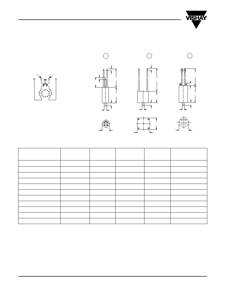
Suppression Filters, Aluminum Case
TECHNICAL DATA:
See page 121 (Document Number 27601).
CIRCUIT DIAGRAM:
DISCRIPTION OF CIRCUIT:
Inductor:
line (blue leads)
Capacitor: load (black leads or flat plugs)
Dimensions in mm
CAPACITANCE
INDUCTANCE
DISCHARGING
RATED
DIMENSIONAL
ORDERING
RESISTOR E
CURRENT*
DIAGRAM
CODE**
(mH)
(M
)
(amps)
0.27
�
FX1 / E+2x2700pFY2
2 x 7
1.5
1.6
1
F1762-0311-020
0.27
�
FX1 / E+2x2700pFY2
2 x 4
1.5
2
1
F1762-0312-020
0.27
�
FX1 / E+2x2700pFY2
2 x 2.5
1.5
2.5
1
F1762-0313-020
0.27
�
FX1 / E+2x2700pFY2
2 x 2.5
1.5
5
1
F1762-0314-020
0.27
�
FX1 / E+2x2700pFY2
2 x 7
1.5
4
2
F1762-0315-020
0.27
�
FX1 / E+2x2700pFY2
2 x 4
1.5
6
2
F1762-0316-020
0.27
�
FX1 / E+2x2700pFY2
2 x 1.5
1.5
10
2
F1762-0317-020
0.27
�
FX1 / E+2x2700pFY2
2 x 1
1.5
15
2
F1762-0318-020
0.47
�
FX1 / E+2x4700pFY2
2 x 1
680
15
3
F1762-0545-020
0.47
�
FX1 / E+2x27 nFY2
2 x 0.3
680
15
3
F1762-0545-030
0.47
�
FX1 / E+2x27 nFY2
2 x 1
680
15
3
F1762-0545-050
*For ambient temperature of > 40
�
C the allowed current decreases in ratio to the rated current.
See diagram on page 111 (Document Number 27502)
**Without discharging resistor
E = discharging resistors on request
APPROVALS:
See general data on page 121 (Document Number 27601)
blue
blue
black
black
25
�
0.5
blue
blue
black
black
y = transparent
black
black
blue
blue
45 - 1
45 - 1
35
�
0.5
M8
M8
M8
12 + 1
12 + 1
12 + 1
75 + 5
50 - 1
70 + 3
50 + 5
5 + 2
5 + 2
5 + 2
100 + 10
150 - 1
6.3
150 + 10
11
�
2
1
2
3
y

F1762
Vishay Roederstein
Document Number 27602
To contact us: RFI@Vishay.com
www.vishay.com
Revision 08-Nov-00
129
Suppression Filters, Aluminum Case
F-1762-0314-020
F-1762-0313-020
F-1762-0312-020
F-1762-031
1-020
F-1762-0317-020
F-1762-0315-020
F-1762-0318-020
F-1762-0316-020
F-1762-0545-030
F-1762-0545-020/050
F-1762-0545-050
-020
80
70
60
50
40
30
20
10
0
0.1
0.2 0.3 0.5 0.7
1
2
3
5
7
10
20
30
f
[MHz]
80
70
60
50
40
30
20
10
0
0.1
0.2 0.3 0.5 0.7
1
2
3
5
7
10
20 30
f
[MHz]
dB
a
80
70
60
50
40
30
20
10
0
0.1
0.2 0.3 0.5
0.7
1
2
3
5
7
10
20
30
f
[MHz]
Asymetrical insertion loss (average)
Measurement at 60
-System with parallel leads
dB
a
dB
a