G, GN
Vishay Dale
www.vishay.com
128
Document Number 30205
Revision 22-Mar-06
For technical questions, contact ww2bresistors@vishay.com
GLOBAL HISTORICAL MIL-PRF-26
MODEL
MODEL
U
V
±
0.5 %,
±
1 %
TYPE
±
0.05 % thru
±
5 %
±
3 % &
±
5 %
±
0.05 %
±
0.1 %
±
0.25 %
±
3 %,
±
5 %
g
G001...80 G-1-80
--
1.0
--
1.0 - 1 k
0.499 - 1 k
0.499 - 3.4 k
0.1 - 3.4 k
0.20
G001...380 G-1-380
RW81
1.0
--
--
0.499 - 1 k
0.499 - 1 k
0.1 - 1 k
0.20
G002
G-2
--
1.5
--
1.0 - 1.3 k
0.499 - 1.3 k
0.499 - 4.9 k
0.1 - 4.9 k
0.21
G003...80 G-3-80
--
2.0
--
1.0 - 2.74 k 0.499 - 2.74 k 0.499 - 10.4 k
0.1 - 10.4 k
0.34
G003...380 G-3-380
RW80
2.0
--
--
0.499 - 2.74 k 0.499 - 2.74 k
0.1 - 2.74 k
0.34
G005
G-5
--
4.0
5.0
0.499 - 6.5 k 0.499 - 6.5 k
0.1 - 24.5 k
0.1 - 24.5 k
0.80
G05C
G-5C
--
5.0
7.0
0.499 - 8.6 k 0.499 - 8.6 k
0.1 - 32.3 k
0.1 - 32.3 k
1.20
G010
G-10
--
7.0
10.0
0.499 - 25.7 k 0.499 - 25.7 k
0.1 - 95.2 k
0.1 - 95.2 k
3.60
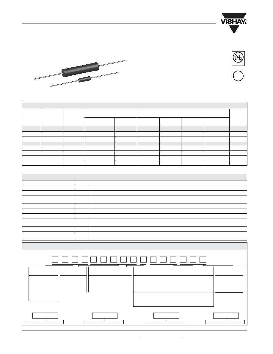
FEATURES
∑ From 1.4 to 4 times higher power ratings than
conventional resistors of equivalent size
∑ High temperature coating (> 350 ∞C)
∑ Complete welded construction
∑ Meets applicable requirements of MIL-PRF-26
∑ Available in non-inductive styles (type GN) with
Aryton-Perry winding for lowest reactive
components
∑ Excellent stability in operation (typical resistance
shift < 0.5 %)
∑ Lead (Pb)-free version is RoHS Compliant
Wirewound Resistors, Military, MIL-PRF-26 Qualified,
Type RW, Precision Power, Silicone Coated
**Vishay Dale G models have two power ratings, depending on operation temperature and stability requirements.
NOTE: Shaded area indicates most popular models.
PARAMETER
UNIT
G RESISTOR CHARACTERISTICS
Temperature Coefficient
ppm/∞C
± 90 for below 1 , ± 50 for 1 to 9.9 , ± 20 for 10 and above
Dielectric Withstanding Voltage
V
AC
500 minimum for G-1-80 thru G-3-380, 1000 minimum for all others
Short Time Overload
≠
5 x rated power for 5 seconds for G-1-80 thru G-5C (Characteristic U),
10 x rated power for 5 seconds for G-10
Maximum Working Voltage
V
(P x R)
1/2
Insulation Resistance
1000 Megohm minimum dry, 100 Megohm minimum after moisture test
Terminal Strength
lb
5 minimum for G-1-80 thru G-3-380, 10 minimum for all others
Solderability
≠
MIL-PRF-26 type - Meets requirements of ANSI J-STD-002
Non Mil type - Terminals are 60/40 electro tin plated to facilitate soldering
Operating Temperature Range
∞C
Characteristic U = - 65/+ 250, Characteristic V = - 65/+ 350
Power Rating
≠
Characteristic U - + 250 ∞C max. hot spot temperature, ± 0.5 % max.
R
in 2000 hr. load life
Characteristic V - + 350 ∞C max. hot spot temperature, ± 3.0 % max.
R
in 2000 hr. load life
TECHNICAL SPECIFICATIONS
STANDARD ELECTRICAL SPECIFICATIONS
RESISTANCE RANGE
MIL. RANGE SHOWN IN BOLD FACE
POWER RATING**
P
25
∞
C
W
WEIGHT
(Typical)
Available
Pb-free
RoHS*
COMPLIANT
e3
* Pb containing terminations are not RoHs compliant, exemptions may apply
GLOBAL MODEL
RESISTANCE
TOLERANCE CODE
PACKAGING
SPECIAL
VALUE
(See Standard
Electrical
Specifications
Global Model
column for
options)
R = Decimal
A = ± 0.05 % B = ± 0.1 %
E70 = Lead (Pb)-free, Tape/Reel (smaller than G010)
(Dash Number)
K = Thousand
C = ± 0.25 % D = ± 0.5 %
E73 = Lead (Pb)-free, Tape/Reel (G010 & larger)
(up to 3 digits)
15R00 = 15
F = ± 1.0 % J = ± 5.0 %
E12 = Lead (Pb)-free, Bulk
From 1-999
10K00 = 10 k
K = 10.0 %
Lead (Pb)-free is not available on RW military type
as applicable
S70 = Tin/Lead, Tape/Reel (smaller than G010)
S73 = Tin/Lead, Tape/Reel (G010 & larger)
B12 = Tin/Lead, Bulk
GLOBAL PART NUMBER INFORMATION
New Global Part Numbering: G00310R00FS7080 (preferred part numbering format)
G
0
0
3
1
0
R
0
0
F
S
7
0
8
0
Historical Part Number example: G-3-80 10
1 % S70 (will continue to be accepted)
HISTORICAL MODEL
RESISTANCE VALUE
TOLERANCE CODE
PACKAGING
G-3-80
10
1 %
S70
www.vishay.com
129
G, GN
Vishay Dale
Document Number 30205
Revision 22-Mar-06
For technical questions, contact ww2bresistors@vishay.com
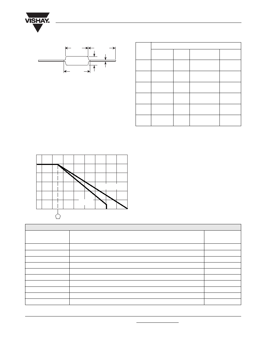
DIMENSIONS
Wirewound Resistors, Military, MIL-PRF-26 Qualified,
Type RW, Precision Power, Silicone Coated
MODEL
DIMENSIONS in inches [millimeters]
L
L
1
C
D
(Max.)**
G-1-80
0.250 ± 0.031
0.281
0.085 ± 0.020
0.020 ± 0.002
G-1-380
[6.35 ± 0.787]
[7.14]
[2.16 ± 0.508]
[0.508 ± 0.051]
G-2
0.312 ± 0.016
0.328
0.078 + 0.016 - 0.031 0.020 ± 0.002
[7.92 ± 0.406]
[8.33]
[1.98 + 0.406 - 0.787] [0.508 ± 0.051]
G-3-80
0.406 ± 0.031
0.437
0.094 ± 0.031
0.020 ± 0.002
G-3-380
[10.31 ± 0.787]
[11.10]
[2.39 ± 0.787]
[0.508 ± 0.051]
G-5
0.562 ± 0.062
0.622
0.188 ± 0.032
0.032 ± 0.002
[14.27 ± 1.57]
[15.80]
[4.78 ± 0.813]
[0.813 ± 0.051]
G-5C
0.500 ± 0.062
0.593
0.218 ± 0.032
0.040 ± 0.002
[12.70 ± 1.57]
[15.06]
[5.54 ± 0.813]
[1.02 ± 0.051]
G-10
0.875 ± 0.062
1.0
0.312 ± 0.032
0.040 ± 0.002
[22.23 ± 1.57]
[25.4]
[7.92 ± 0.813]
[1.02 ± 0.051]
C
D
L
1.50
[38.10]*
Min.
L
1
*On some standard reel pack methods, the leads may be trimmed to
a shorter length than shown.
**L
1
(Max.) dimension is clean lead to clean lead.
MATERIAL SPECIFICATIONS
Element: Copper-nickel alloy or nickel-chrome alloy,
depending on resistance value
Core: Ceramic, Beryllium oxide or alumina, depending on
resistor model
Coating: Special high temperature silicone
Standard Terminals: 100 % Sn, or 60/40 Sn/Pb coated
Copperweld
Æ
.
NOTE: Military (RW) parts are only available with 60/40 Sn/
Pb finish.
End Caps: Stainless steel
Part Marking: DALE, Model, Wattage*, Value, Tolerance,
Date Code
*Wattage marked on part will be "U" characteristic
PERFORMANCE
TEST
CONDITIONS OF TEST
TEST LIMITS
(CHARACTERISTIC U)
Thermal Shock
Rated power applied until thermally stable, then a minimum of 15 minutes at - 55 ∞C
± (0.2 % + 0.05 ) R
Short Time Overload
5 x power (G-1-80 thru G-5C), 10 x power (G-10) for 5 seconds
± (0.2 % + 0.05 ) R
Dielectric Withstanding Voltage
1000 V rms, one minute
± (0.1 % + 0.05 ) R
Low Temperature Storage
- 65 ∞C for 24 hours
± (0.2 % + 0.05 ) R
High Temperature Exposure
250 hours at + 250∞ (Characteristic U)
± (0.5 % + 0.05 ) R
Moisture Resistance
MIL-STD-202 Method 106, 7b not applicable
± (0.2 % + 0.05 ) R
Shock, Specified Pulse
MIL-STD-202 Method 213, 100g's for 6 milliseconds, 10 shocks
± (0.1 % + 0.05 ) R
Vibration, High Frequency
Frequency varied 10 to 2000 Hz, 20g peak, 2 directions 6 hours each
± (0.1 % + 0.05 ) R
Load Life
2000 hours at rated power, + 25 ∞C, 1.5 hours "ON", 0.5 hours "OFF"
± (0.5 % + 0.05 ) R
Terminal Strength
5 to 10 sec., 5 or 10 lb pull test (depending on size), torsion test - 3 alternating directions, 360 ∞C each
± (0.1 % + 0.05 ) R
GN NON-INDUCTIVE
Models of equivalent physical and electrical specifications are
available with non-inductive (Aryton-Perry) winding. They are
identified by inserting the letter N after G in the model number
(GN-5, for example). Two conditions apply:
1. For GN models, divide maximum resistance values by two
2. Body O.D. on GN-5C may exceed that of the G-5C by 0.010"
TERMINATION
When G resistors will be operated at full rated power,
resistance welding or high temperature solder are the
recommended termination methods. Termination should be
made within 1/2 inch from end of resistor body.
Derating
120
100
80
60
40
20
0-65 -50 0 50 150 250 350
AMBIENT TEMPERATURE IN
∞
C
RA
TED POWER IN %
CHAR. V
CHAR. U
25

Legal Disclaimer Notice
Vishay
Document Number: 91000
www.vishay.com
Revision: 08-Apr-05
1
Notice
Specifications of the products displayed herein are subject to change without notice. Vishay Intertechnology, Inc.,
or anyone on its behalf, assumes no responsibility or liability for any errors or inaccuracies.
Information contained herein is intended to provide a product description only. No license, express or implied, by
estoppel or otherwise, to any intellectual property rights is granted by this document. Except as provided in Vishay's
terms and conditions of sale for such products, Vishay assumes no liability whatsoever, and disclaims any express
or implied warranty, relating to sale and/or use of Vishay products including liability or warranties relating to fitness
for a particular purpose, merchantability, or infringement of any patent, copyright, or other intellectual property right.
The products shown herein are not designed for use in medical, life-saving, or life-sustaining applications.
Customers using or selling these products for use in such applications do so at their own risk and agree to fully
indemnify Vishay for any damages resulting from such improper use or sale.