
VISHAY
GBPC6005 thru GBPC610
Document Number 88613
10-Dec-04
Vishay Semiconductors
www.vishay.com
1
Case Style GBPC6
~
~
~
~
Glass Passivated Single-Phase Bridge Rectifier
Major Ratings and Characteristics
I
F(AV)
6 A
V
RRM
50 V to 1000 V
I
FSM
175 A
I
R
5 µA
V
F
1.0 V
T
j
max.
150 ∞C
Features
∑ UL Recognition file number E54214
∑ Ideal for printed circuit boards
∑ Typical I
R
less than 0.5 µA
∑ High surge current capability
∑ High case dielectric strength 1500 V
RMS
∑ Meets MSL level 1, per J-STD-020C
Typical Applications
General purpose use in ac-to-dc bridge full wave rec-
tification for Power Supply, Home Appliances, Office
Equipment, Industrial Automation applications
Mechanical Data
Case: GBPC6
Epoxy meets UL-94V-0 Flammability rating
Terminals: Silver plated (E4 Suffix) leads, solderable
per J-STD-002B and MIL-STD-750, Method 2026
Polarity: As marked, Positive lead by belevled corner
Mounting Torque: 10 cm-kg (8.8 inches-lbs) max.
Recommended Torque: 5.7 cm-kg (5 inches-lbs)
Maximum Ratings
Ratings at 25 ∞C ambient temperature unless otherwise specified.
Parameter
Symbols GBPC
6005
GBPC
601
GBPC
602
GBPC
604
GBPC
606
GBPC
608
GBPC
610
Unit
Maximum repetitive peak reverse voltage
V
RRM
50
100
200
400
600
800
1000
V
Maximum RMS bridge input voltage
V
RMS
35
70
140
280
420
560
700
V
Maximum DC blocking voltage
V
DC
50
100
200
400
600
800
1000
V
Maximum average forward T
C
= 50 ∞C
(1)(2)
rectified output current at T
A
= 40 ∞C
(3)
I
F(AV)
6.0
3.0
A
Peak forward surge current single sine-wave
superimposed on rated load
I
FSM
175
A
Rating for fusing (t < 8.3 ms)
I
2
t
127
A
2
sec
Operating junction and storage temperature
range
T
J
, T
STG
- 55 to + 150
∞C
www.vishay.com
2
Document Number 88613
10-Dec-04
VISHAY
GBPC6005 thru GBPC610
Vishay Semiconductors
Electrical Characteristics
Ratings at 25 ∞C ambient temperature unless otherwise specified.
Thermal Characteristics
Ratings at 25 ∞C ambient temperature unless otherwise specified.
Notes:
(1) Bolt down on heat-sink with silicone thermal compound between bridge and mounting surface for maximum heat transfer with #6 screw
(2) Unit mounted on 5.5 x 6.0 x 0.11" thick (14 x 15 x 0.3 cm) Al. Plate
(3) Unit mounted on P.C.B. at 0.375" (9.5 mm) lead length with 0.5 x 0.5" (12 x 12 mm) copper pads
Ratings and Characteristics Curves
(T
A
= 25
∞C unless otherwise noted)
Parameter
Test condition
Symbols
GBPC
6005
GBPC
601
GBPC
602
GBPC
604
GBPC
606
GBPC
608
GBPC
610
Unit
Maximum instantaneous
forward voltage drop per leg
at 3.0 A
V
F
1.0
V
Maximum DC reverse
current at rated DC blocking
voltage per leg
T
A
= 25 ∞C
T
A
= 125 ∞C
I
R
5.0
500
µA
Typical junction capacitance
per leg
at 4.0 V, 1 MHz
C
J
186
90
pF
Parameter
Symbols
GBPC
6005
GBPC
601
GBPC
602
GBPC
604
GBPC
606
GBPC
608
GBPC
610
Unit
Typical thermal resistance per leg
(1)
R
JA
R
JC
22
7.3
∞C/W
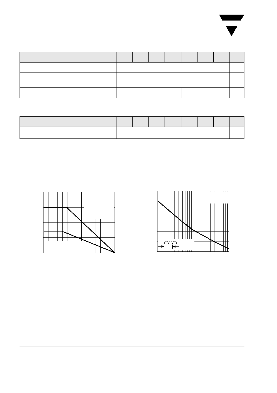
Figure 1. Derating Curve Output Rectified Current
Temperature (∞C)
A
verage
Forward
Output
Current
(A)
0
50
100
150
0
2.0
4.0
6.0
8.0
Case Temperature,
T
C
Heatsink Mounting
5.5 x 6.0 x 0.11" Thk
(14 x 15 x 0.3 cm)
AL. Plate
60 H
Z
Resistive or
Inductive Load
Ambient Temperature, T
A
P.C.B. Mounting
0.375" (9.5 mm) Lead Length
Figure 2. Maximum Non-Repetitive Peak Forward Surge Current
Per Leg
Number of Cycles at 60 H
Z
Peak
Forward
Surge
Current
(A)
1
10
100
50
75
100
125
150
175
200
1.0 Cycle
T
J
= T
J max.
Single Half Sine-Wave
(JEDEC Method)

VISHAY
GBPC6005 thru GBPC610
Document Number 88613
10-Dec-04
Vishay Semiconductors
www.vishay.com
3
Package outline dimensions in inches (millimeters)
Figure 3. Typical Forward Characteristics Per Leg
Figure 4. Typical Reverse Leakage Characteristics Per Leg
Instantaneous Forward Voltage (V)
Instantaneous
Forward
Current
(A)
10
0.4
1.0
1.8
0.01
0.1
1
100
0.6
0.8
1.2
1.6
1.4
T
J
= 25 ∞C
Pulse Width = 300
µs
1% Duty Cycle
Percent of Rated Peak Reverse Voltage (%)
Instantaneous
Reverse
Current
(
µ
A)
0
20
40
60
80
100
0.1
1
10
100
T
A
= 125 ∞C
T
J
= 25 ∞C
T
J
= 100 ∞C
Figure 5. Typical Junction Capacitance Per Leg
Figure 6. Typical Transient Thermal Impedance Per Leg
Reverse Voltage (V)
Junction
Capacitance,
pF
0.1
1
10
100
10
100
1,000
50 - 400 V
600 - 1000 V
T
J
= 25 ∞C
f = 1.0 MH
Z
Vsig = 50mVp-p
t, Heating Time (sec.)
T
ransient
Thermal
Impedance
(
∞
C/W)
0.01
0.1
1
10
100
0.1
1
10
100
HOLE FOR
#6 SCREW
0.158 (4.01)
0.142 (3.61)
DIA.
0.128 (3.25)
0.048 (1.22)
0.200 (5.08)
0.160 (4.06)
0.750
(19.05)
MIN.
0.040 (1.02) TYP.
0.094 (2.4) x 45 degrees
0.445 (11.30)
0.405 (10.29)
0.630 (16.00)
0.590 (14.98)
AC
AC
Polarity shown on side of case: Positive lead by beveled corner
0.445 (11.30)
0.405 (10.29)
0.630 (16.00)
0.590 (14.98)
DIA.
0.042(1.07)
0.038(0.96)
Case Style GBPC6