RH, NH
Vishay Dale
www.vishay.com
122
Document Number 30201
Revision 09-Sep-04
For technical questions, contact ww2bresistors@vishay.com
FEATURES
∑ Molded construction for total environmental protection
∑ Complete welded construction
∑ Meets applicable requirements of MIL-PRF-18546
∑ Available in non-inductive styles (type NH) with Aryton-
Perry winding for lowest reactive components
∑ Mounts on chassis to utilize heat-sink effect
∑ Excellent stability in operation
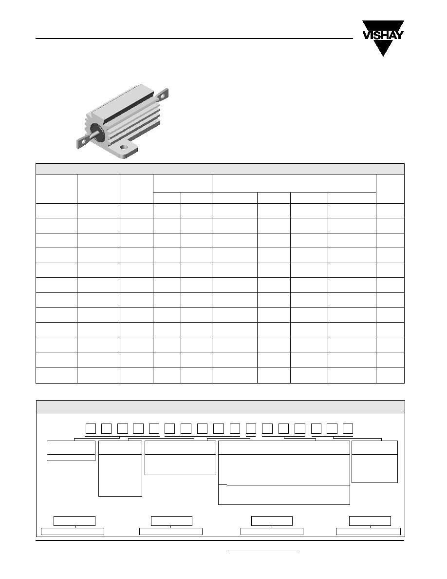
Wirewound Resistors, Military, MIL-PRF-18546 Qualified,
Type RE, Aluminum Housed, Chassis Mount
NOTE: Figures in parentheses on RH-5 and RH-10 indicate wattage printed on parts, new construction allows these resistors to be rated at
higher wattage but will only be printed with the higher wattage on customer request.
RESISTANCE RANGE
MIL. RANGE SHOWN IN BOLD FACE
STANDARD ELECTRICAL SPECIFICATIONS
GLOBAL
MODEL
RH005
NH005
RH010
NH010
RH025
NH025
RH050
NH050
RH100
NH100
RH250
NH250
MIL-PRF-
18546
TYPE
--
RE60G
--
RE60N
--
RE65G
--
RE65N
--
RE70G
--
RE70N
--
RE75G
--
RE75N
--
RE77G
--
RE77N
--
RE80G
--
RE80N
DALE
7.5 (5)
7.5 (5)
12.5 (10)
12.5 (10)
25
25
50
50
100
100
250
250
MILITARY
5
5
10
10
20
20
30
30
75
75
120
120
±
0.05%,
±
0.1%
0.5 - 6.75k
--
0.5 - 2.32k
--
0.5 - 12.7k
--
0.5 - 4.45k
--
0.5 - 25.7k
--
0.5 - 9.09k
--
0.5 - 73.4k
--
0.5 - 26k
--
0.5 - 90k
--
0.5 - 37.5k
--
0.5 - 116k
--
0.5 - 48.5k
--
±
0.25%
0.1 - 8.6k
--
0.1 - 3.27k
--
0.1 - 16.69k
--
0.1 - 5.54k
--
0.1 - 32.99k
--
0.1 - 12.8k
--
0.1 - 96k
--
0.1 - 36.7k
--
0.1 - 90k
--
0.1 - 37.5k
--
0.1 - 116k
--
0.1 - 48.5k
--
±
0.5%
0.05 - 8.6k
--
0.05 - 3.27k
--
0.05 - 16.69k
--
0.05 - 5.54k
--
0.05 - 32.99k
--
0.05 - 12.8k
--
0.05 - 96k
--
0.05 - 36.7k
--
0.05 - 90k
--
0.05 - 37.5k
--
0.05 - 116k
--
0.05 - 48.5k
--
±
1%,
±
3%,
±
5%
0.02 - 24.5k
0.10 - 3.32k
0.05 - 12.75k
1.0 - 1.65k
0.01 - 47.1k
0.10 - 5.62k
0.05 - 23.5k
1.0 - 2.8k
0.01 - 95.2k
0.10 - 12.1k
0.05 - 47.6k
1.0 - 6.04k
0.01 - 273k
0 .10 - 39.2k
0.05 - 136k
1.0 - 19.6k
0.05 - 90k
0.05 - 29.4k
0.05 - 37.5k
1.0 - 14.7k
0.05 - 116k
0.10 - 35.7k
0.05 - 48.5k
1.0 - 17.4k
WEIGHT
(Typical)
g
3
3.3
6
8.8
13
16.5
28
35
350
385
630
690
POWER RATING
P
25
∞
C
W
HISTORICAL
MODEL
RH-5
NH-5
RH-10
NH-10
RH-25
NH-25
RH-50
NH-50
RH-100
NH-100
RH-250
NH-250
GLOBAL MODEL
RESISTANCE
TOLERANCE CODE
PACKAGING
SPECIAL
VALUE
RH005
L = Milliohm
A = ± 0.05% B = ± 0.1%
*E02 = Lead Free, Card Pack (RH005 ≠ RH050)
(Dash Number)
R = Decimal
C = ± 0.25% D = ± 0.5%
*E01 = Lead Free, Skin Pack (RH100 & RH250)
(up to 3 digits)
K = Thousand
F = ± 1.0% J = ± 5.0%
Lead Free is not available on RE military type
From 1-999
8L000 = 0.008
*(Lead Free parts to be released Q1 2005)
as applicable
15R00 = 15
10K00 = 10K
C02 = Tin/Lead, Card Pack (RH005 ≠ RH050)
J01 = Tin/Lead, Skin Pack (RH100 & RH250)
GLOBAL PART NUMBER INFORMATION
New Global Part Numbering: RH0054R125FC02 (preferred part numbering format)
R
H
0
0
5
4
R
1
2
5
F
C
0
2
Historical Part Number example: RH-5 4.125 1% C02 (will continue to be accepted)
HISTORICAL MODEL
RESISTANCE VALUE
TOLERANCE CODE
PACKAGING
RH-5
4.125
1%
C02

www.vishay.com
123
RH, NH
Vishay Dale
Document Number 30201
Revision 09-Sep-04
For technical questions, contact ww2bresistors@vishay.com
DIMENSIONS
Wirewound Resistors, Military, MIL-PRF-18546 Qualified,
Type RE, Aluminum Housed, Chassis Mount
MODEL
DIMENSIONS in inches [millimeters]
A
B
C
D
E
F
G
H
J
K
L
M
N
P
RH-5
0.444
0.490
0.600
1.125
0.334
0.646
0.320
0.065
0.133
0.078
0.093
0.078
0.050
0.266
NH-5
± 0.005 ± 0.005 ± 0.031
± 0.062 ± 0.015
± 0.015 ± 0.015 ± 0.010 ± 0.010 ± 0.010 ± 0.005 ± 0.015 ± 0.005 ± 0.062
[11.28
[12.45
[15.24
[28.58
[8.48
[16.41
[8.13
[1.65
[3.38
[1.98
[2.36
[1.98
[1.27
[6.76
± 0.127] ± 0.127] ± 0.787]
± 1.57] ± 0.381]
± .381] ± 0.381] ± 0.254] ± 0.254] ± 0.254] ± 0.127] ± .381] ± 0.127] ± 1.57]
RH-10
0.562
0.625
0.750
1.375
0.420
0.800
0.390
0.075
0.165
0.093
0.094
0.102
0.085
0.312
NH-10
± 0.005 ± 0.005 ± 0.031
± 0.062 ± 0.015
± 0.015 ± 0.015 ± 0.010 ± 0.010 ± 0.010 ± 0.005 ± 0.015 ± 0.005 ± 0.062
[14.27
[15.88
[19.05
[34.93
[10.67
[20.32
[9.91
[1.91
[4.19
[2.36
[2.39
[2.59
[2.16
[7.92
± 0.127] ± 0.127] ± 0.787]
± 1.57] ± 0.381] ± 0.381] ± 0.381] ± 0.254] ± 0.254] ± 0.254] ± 0.127] ± 0.381] ± 0.127] ± 1.57]
RH-25
0.719
0.781
1.062
1.938
0.550
1.080
0.546
0.075
0.231
0.172
0.125
0.115
0.085
0.438
NH-25
± 0.005 ± 0.005 ± 0.031
± 0.062 ± 0.015
± 0.015 ± 0.015 ± 0.010 ± 0.010 ± 0.010 ± 0.005 ± 0.015 ± 0.005 ± 0.062
[18.26
[19.84
[26.97
[49.23
[13.97
[27.43
[13.87
[1.91
[5.87
[4.37
[3.18
[2.92
[2.16
[11.13
± 0.127] ± 0.127] ± 0.787]
± 1.57] ± .381]
± 0.381] ± 0.381] ± 0.254] ± 0.254] ± 0.254] ± 0.127] ± 0.381] ± 0.127] ± 1.57]
RH-50
1.562
0.844
1.968
2.781
0.630
1.140
0.610
0.088
0.260
0.196
0.125
0.107
0.085
0.438
NH-50
± 0.005 ± 0.005 ± 0.031
± 0.062 ± 0.015
± 0.015 ± 0.015 ± 0.010 ± 0.010 ± 0.010 ± 0.005 ± 0.015 ± 0.005 ± 0.062
[39.67
[21.44
[49.99
[70.64
[16.00
[28.96
[15.49
[2.24
[6.60
[4.98
[3.18
[2.72
[2.16
[11.13
± 0.127] ± 0.127] ± 0.787]
± 1.57] ± 0.381] ± 0.381] ± 0.381] ± 0.254] ± 0.254] ± 0.254] ± 0.127] ± 0.381] ± 0.127] ± 1.57]
RH-250, NH-250
RH-100, NH-100
2.25
±
0.010
[57.15
±
0.254]
0.989
±
0.031
[25.12
±
0.787]
2.812
±
0.031
[71.42
±
0.787]
3.50
±
0.031
[88.90
±
0 .787]
Nickel Plated
Brass Nut
Stainless Steel Stud
1.125
±
0.031
[28.58
±
0.787]
0.188
±
0.010
[4.78
±
0.254]
Dia. Typ.
12 - 24
UNC-2A
Thd. Typ.
2.75
±
0.010
[69.85
±
0.254]
.375
±
0.031
[9.52
±
0.787]
5.478
±
0.093
[139.14
±
2.36]
1.75
±
0.031
[44.45
±
0.787]
2.188
±
0.031
[55.58
±
0.787]
2.125
±
0.031
[53.98
±
0.787]
0.250
±
0.031
[6.35
±
0.787]
Typ.
4.50
±
0.031
[114.30
±
0.787]
2.50
±
0.010
[63.50
±
0.254]
Nickel Plated
Brass Nut
Stainless Steel Stud
7.0
±
.093 [177.80
±
2.36]
0.875
±
0.010
[22.23
±
.254]
3.0
±
0.010
[76.20
±
.254]
3.875
±
0.010
[98.42
±
0.254]
0.770
±
0.015
[19.56
±
0.381]
0.188
±
0.031
[4.78
±
0.787]
Typ.
1.812
±
0.031
[46.02
±
0.787]
.312
±
0.031
[7.92
±
0.787]
1.25
±
0.062
[31.75
±
1.575]
1.25
±
0.062
[31.75
±
1.575]
1/4 - 20
UNC-2A Thd.Typ.
0.188
±
0.010
[4.78
±
0.254]
Dia. Typ.
0.955
±
0.015
[24.26
±
.381]
RH-5, -10, -25, -50
NH-5, -10, -25, -50
P
D
C
A
L
M
N
J
F
E
H
G
K
B
3.0
±
.031
[76.20
±
0.787]

RH, NH
Vishay Dale
www.vishay.com
124
Document Number 30201
Revision 09-Sep-04
For technical questions, contact ww2bresistors@vishay.com
Wirewound Resistors, Military, MIL-PRF-18546 Qualified,
Type RE, Aluminum Housed, Chassis Mount
POWER RATING
Vishay RH resistor wattage ratings are based on mounting to the following heat sink:
RH-5 and RH-10:
4" x 6" x 2" x 0.040" thick aluminum chassis (129 sq. in. surface area)
RH-25:
5" x 7" x 2" x 0.040" thick aluminum chassis (167 sq. in. surface area)
RH-50:
12" x 12" x 0.059" thick aluminum panel (291 sq. in. surface area)
RH-100 and RH-250:
12" x 12" x 0.125" thick aluminum panel (294 sq. in. surface area)
AMBIENT TEMPERATURE DERATING
Derating is required for ambient temperatures above 25∞C, see the following graph.
Curves A, B, C apply to operation of unmounted resistors. Curve D applies to all types when mounted to specified heat sink.
A = RH-5 and RH-10 size resistor, unmounted
B = RH-25 size resistor, unmounted
C = RH-50, RH-100 and RH-250 size resistor, unmounted
D = All types mounted to recommended aluminum heat sink
RA
TED POWER IN %
Derating
REDUCED HEAT SINK DERATING:
Derating is also required when recommended heat
sink area is reduced.
A = RH-5 and RH-10 size resistor
B = RH-25 size resistor
C = RH-50, RH-100 and RH-250 size resistor
100
90
80
70
60
50
40
30
20
10
0
0
20
40
60
80
100
% OF RECOMMENDED HEAT SINK AREA
RA
TED POWER IN %
Heat Sink Derating
A
C
B
-55 -50
0
50
150
250
AMBIENT TEMPERATURE IN
∞
C
25
120
A
C
D
B
0
20
40
60
80
100
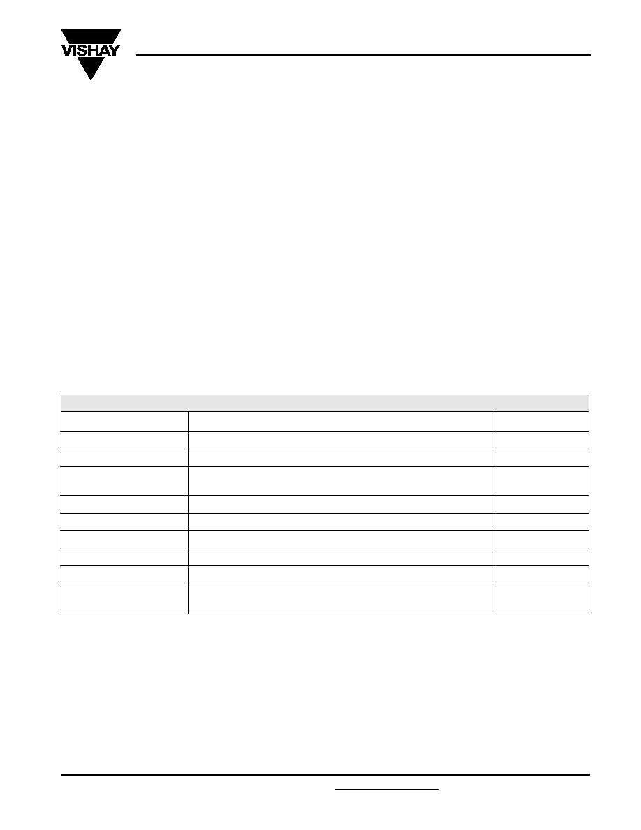
PARAMETER
UNIT
RH RESISTOR CHARACTERISTICS
Temperature Coefficient
ppm/∞C
± 100 for 0.1 to 0.99, ± 50 for 1 to 9.9, ± 20 for 10 and above
Dielectric Withstanding Voltage
V
AC
1000 for RH-5, RH-10 and RH-25, 2000 for RH-50, 4500 for RH-100 and RH-250
Short Time Overload
-
5 x rated power for 5 seconds
Maximum Working Voltage
V
(P X R)
1/2
Insulation Resistance
10,000 Megohm minimum dry, 1000 Megohm minimum after moisture test
Terminal Strength
lb
5 minimum for RH-5 and RH-10, 10 minimum for all others
Solderability
-
MIL-PRF-18546 Type - Meets requirements of ANSI J-STD-002
OperatingTemperature Range
∞C
- 55/+ 250
TECHNICAL SPECIFICATIONS
www.vishay.com
125
RH, NH
Vishay Dale
Document Number 30201
Revision 09-Sep-04
For technical questions, contact ww2bresistors@vishay.com
Wirewound Resistors, Military, MIL-PRF-18546 Qualified,
Type RE, Aluminum Housed, Chassis Mount
MATERIAL SPECIFICATIONS
Element: Copper-nickel alloy or nickel-chrome alloy,
depending on resistance value
Core: Ceramic, steatite or alumina, depending on physical
size
Encapsulant: Silicone molded construction
Housing: Aluminum with hard anodic coating
End Caps: Stainless steel
Standard Terminals: 100% Sn, w/Nickel underplate, or 60/
40 Sn/Pb, w/Nickel underplate, coated Copperweld
Æ
on RH-5
through RH-50 size. Threaded stainless steel terminals on
RH-100 and RH-250.
NOTE: Military (RE) parts are only available with 60/40 Sn/Pb
finish.
Part Marking: DALE, Model, Wattage, Value, Tolerance,
Date Code
NH NON-INDUCTIVE
Models of equivalent physical and electrical specifications are
available with non-inductive (Aryton-Perry) winding. They are
identified by substituting the letter N for R in the model
number (NH-5, for example).
SPECIAL MODIFICATIONS
A number of special modifications to the aluminum housed
resistor style are available upon request. Special
modifications include:
∑ Terminal configurations and materials
∑ Resistance values and tolerances
∑ Low resistance temperature coefficient (RTC)
∑ Housing configuration
∑ Threaded mounting holes
∑ Preconditioning and other additional testing
APPLICABLE MIL SPECIFICATIONS
MIL-PRF-18546 is the military specification covering
aluminum housed, chassis mount, power resistors. VISHAY
RH and NH resistors are listed as qualified on the
MIL-PRF-18546 QPL.
PERFORMANCE
TEST
CONDITIONS OF TEST
TEST LIMITS
Thermal Shock
Rated power applied until thermally stable, then a minimum of 15 minutes at - 55∞C
± (0.5% + 0.05) R
Short Time Overload
5 x rated power for 5 seconds
± (0.5% + 0.05) R
1000Vrms for RH-5, RH-10 and RH-25; 2000Vrms for RH-50
4500Vrms for RH-100 and RH-250; duration one minute
Temperature
250∞C for 2 hours
± (0.5% + 0.05) R
Moisture Resistance
MIL-STD-202 Method 106, 7b not applicable
± (1.0% + 0.05) R
Shock, Specified Pulse
MIL-STD-202 Method 213, 100g's for 6 miliseconds, 10 shocks
± (0.2% + 0.05) R
Vibration, High Frequency
Frequency varied 10 to 2000Hz, 20g peak, 2 directions 6 hours each
± (0.2% + 0.05) R
Load Life
1000 hours at rated power, + 25∞C, 1.5 hours "ON", 0.5 hours "OFF"
± (1.0% + 0.05) R
30 second, 5 pound pull test for RH-5 and RH-10, 10 pound pull test for other
sizes, torque test - 24 pound inch for RH-100 and 32 pound inch for RH-250
Dielectric Withstanding Voltage
± (0.2% + 0.05) R
Terminal Strength
± (0.2% + 0.05) R

Legal Disclaimer Notice
Vishay
Document Number: 91000
www.vishay.com
Revision: 08-Apr-05
1
Notice
Specifications of the products displayed herein are subject to change without notice. Vishay Intertechnology, Inc.,
or anyone on its behalf, assumes no responsibility or liability for any errors or inaccuracies.
Information contained herein is intended to provide a product description only. No license, express or implied, by
estoppel or otherwise, to any intellectual property rights is granted by this document. Except as provided in Vishay's
terms and conditions of sale for such products, Vishay assumes no liability whatsoever, and disclaims any express
or implied warranty, relating to sale and/or use of Vishay products including liability or warranties relating to fitness
for a particular purpose, merchantability, or infringement of any patent, copyright, or other intellectual property right.
The products shown herein are not designed for use in medical, life-saving, or life-sustaining applications.
Customers using or selling these products for use in such applications do so at their own risk and agree to fully
indemnify Vishay for any damages resulting from such improper use or sale.