
www.vishay.com
71
S Series
Vishay Foil Resistors
Document Number: 63001
Revision 23-May-06
THROUGH HOLE
For technical questions, contact: foil@vishay.com
SALES
∑ AMERICAS: foilsales.usa@vishay.com ∑ ASIA/JAPAN: foilsales.asia@vishay.com
∑ UK/HOLLAND/SCANDINAVIA: foilsales.eunorth@vishay.com
∑ GERMANY/CZECH REPUBLIC/AUSTRIA: foilsales.eucentral@vishay.com ∑ FRANCE/SWITZERLAND/SOUTHERN EUROPE: foilsales.eusouth@vishay.com ∑ ISRAEL: foilsales.israel@vishay.com
IMPROVED PRODUCT
High Precision Foil Resistor with TCR of
±
2.0ppm/
∞
C,
Tolerance of
±
0.005% and Load Life Stability of
±
0.005%
INTRODUCTION
Bulk Metal
Æ
Foil (BMF) Technology outperforms all other
resistor technologies available today for applications that
require high precision and high stability.
This technology has been pioneered and developed by
VISHAY, products based on this technology are the most
suitable for a wide range of applications. BMF technology
allows us to produce customer orientated products designed
to satisfy challenging and specific technical requirements.
Model S Series made from Vishay BMF offers low TCR,
excellent load life stability, tight tolerance, fast response time,
low current noise, low thermal EMF and low voltage
coefficient, all in one resistor.
The S Series is virtually insensitive to destabillizing factors.
The resistor element is a solid alloy that displays the desirable
bulk properties of its parent material, thus it is inherently
stable and noise free.
Vishay Bulk Metal
Æ
S Series are the modern generation of
precision resistors, their design gives you a unique
combination of characteristics found in no other single
resistor- and they're all standard.
Our Application Engineering Department is available to
advise and to make recommendation for non-standard
technical requirements and special applications, please
contact us.
APPLICATIONS
∑ High Precision Amplifiers
∑ Down-hole (High Temperature)
∑ High Precision Instrumentation
∑ Medical and Test Equipment
∑ Industrial
∑ Audio (High End Stereo Equipment)
∑ EB Applications (electron beam scanning and recording
equipment, electron microscopes)
∑ Military, Airborne
∑ Measurement Instrumentation
FEATURES
∑ Very low Temperature Coefficient of Resistance
(TCR): ** - 55
∞
C to + 125
∞
C, 25
∞
C Ref
- S102C Series:
±
2ppm/
∞
C typical,
±
4.5ppm/
∞
C max.
- S102K Series:
±
1ppm/
∞
C typical,
±
2.5ppm/
∞
C max.
∑ Load Life Stability: to
±
0.005% at 70
∞
C, 2000hrs
∑ Tight Tolerance:
±
0.005%
∑ Resistance Range: 0.5
to 1M
(higher or lower values of
resistance are available)
∑ Shelf Life Stability:
to Maximum 0.0025%, 1 year
∑ Rated Power: to 1W at + 125
∞
C
∑ Matched sets are available per request
(TCR Tracking: to 0.5ppm/
∞
C)
∑ Voltage Coefficient: < 0.1ppm/V
∑ Low Inductance: < 0.08
µ
H
∑ Current Noise: < - 40dB
∑ Rise/Decay Time: 1ns without ringing
∑ Thermal EMF: 0.05
µ
V/
∞
C
∑ Terminal Finishes Available:
Lead (Pb)-free (Sn 100%)
Tin/Lead Alloy (Sn 60%, Pb 40%)
∑ For better performances please review the Z201 datasheet
** For values below 50
please contact Application Engineering
Any value at any tolerance
available within resistance range
FIG 1 - FOIL RESISTOR TCR COMPARISON OF
FOIL ALLOYS IN MILITARY RANGE
-50
-25
0
+25
+50
+75
+100
+125
-55
C Alloy
2ppm/
∞
C
K Alloy
1ppm/
∞
C
1ppm/
∞
C
2ppm/
∞
C
+150
+100
+50
0
-50
-100
-150
-200
R
R
(ppm)
Temperature (∞C)
Available
Pb-free
RoHS*
COMPLIANT
* Pb containing terminations are not RoHS compliant, exemptions may apply

Document Number: 63001
Revision 23-May-06
www.vishay.com
72
S Series
Vishay Foil Resistors
THROUGH HOLE
For technical questions, contact: foil@vishay.com
SALES
∑ AMERICAS: foilsales.usa@vishay.com ∑ ASIA/JAPAN: foilsales.asia@vishay.com
∑ UK/HOLLAND/SCANDINAVIA: foilsales.eunorth@vishay.com
∑ GERMANY/CZECH REPUBLIC/AUSTRIA: foilsales.eucentral@vishay.com ∑ FRANCE/SWITZERLAND/SOUTHERN EUROPE: foilsales.eusouth@vishay.com ∑ ISRAEL: foilsales.israel@vishay.com
IMPROVED PRODUCT
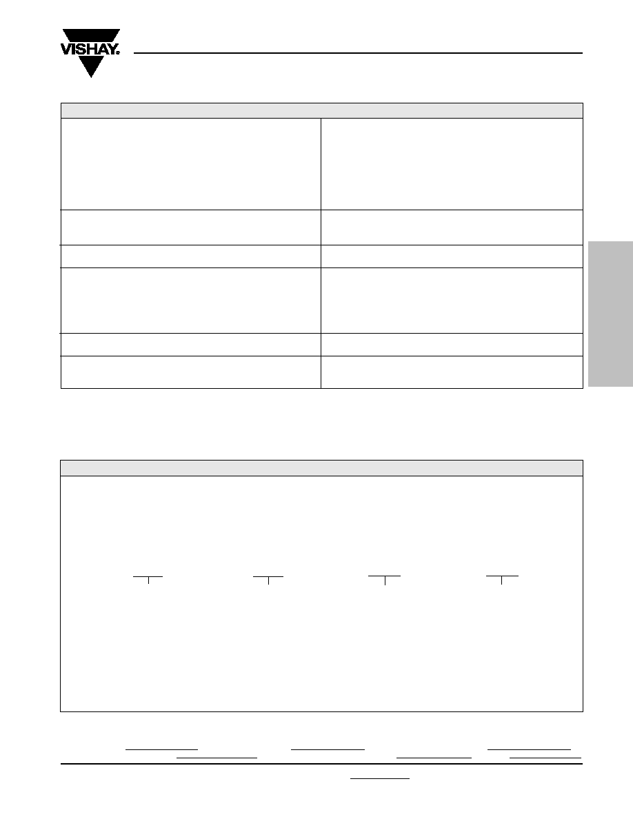
*The standoffs shall be so located as to give a lead clearance of 0.010" minimum between the resistor body and the printed circuit board
when the standoffs are seated on the printed circuit board. This is to allow for proper cleaning of flux and other contaminants from the
unit after all soldering processes.
FIGURE 2 - STANDARD IMPRINTING AND DIMENSIONS
TABLE 1 - MODEL SELECTION
MODEL
RESISTANCE MAXIMUM
AMBIENT
AVERAGE
DIMENSIONS
NUMBER
RANGE
WORKING
POWER RATING
WEIGHT
(
)
VOLTAGE @ + 70
∞
C @ + 125
∞
C IN GRAMS INCHES
mm
*F (INCHES)
S102C (S102J**)
1 to 150K
300
0.6W
0.3W
0.6
W: 0.105
±
0.010 2.67
±
0.25
up to 100K
L: 0.300
±
0.010 7.62
±
0.25
H: 0.326
±
0.010 8.28
±
0.25
ST: 0.010 Minimum 0.254 Minimum
S102K (S102L**)
1 to 100K
0.4W
0.2W
SW: 0.040
±
0.005 1.02
±
0.13
over 100K
LL: 1.000
±
0.125 25.4
±
3.18
LS: 0.150
±
0.005
4
3.81
±
0.13
S104D (S104F*)
1 to 500K
350
1.0W
0.5W
1.4
W: 0.160 Maximum 4.06 Maximum
(0.138)
up to 200K
L: 0.575 Maximum 14.61 Maximum
(0.565)
H: 0.413 Maximum 10.49 Ma ximum
(0.413)
ST: 0.035
±
0.005 0.889
±
0.13
S104K
1 to 300K
0.6W
0.3W
SW: 0.050
±
0.005 1.27
±
0.13
over 200K
LL: 1.000
±
0.125 25.4
±
3.18
LS: 0.400
±
0.020 10.16
±
0.51
S105D (S105F*)
1 to 750K
350
1.5W
0.75W
1.9
W: 0.160 Maximum 4.06 Maximum
(0.138)
up to 300K
L: 0.820 Maximum 20.83 Maximum
(0.890)
H: 0.413 Maximum 10.49 Maximum
(0.413)
ST: 0.035
±
0.005 0.889
±
0.13
S 105K
1 to 500K
0.8W
0.4W
SW: 0.050
±
0.005 1.27
±
0.13
over 300K
LL: 1.000
±
0.125 25.4
±
3.18
LS: 0.650
±
0.020 16.51
±
0.51 (0.7
±
0.02)
S106D
0.5 to 1M
500
2.0W
1.0W
4.0
W: 0.260 Maximum 6.60 Maximum
up to 400K
L: 1.200 Maximum 30.48 Maximum
H: 0.413 Maximum 10.49 Maximum
ST: 0.035
±
0.005 0.889
±
0.13
S106K
0.5 to 600K
1.0W
0.5W
SW: 0.050
±
0.005 1.27
±
0.13
over 400K
LL: 1.000
±
0.125 25.4
±
3.18
LS: 0.900
±
0.020 22.86
±
0.51
*S104F and S105F have different package dimensions (see last
column). All other specifications are the same.
**0.200" (5.08mm) lead spacing available - specify S102J for
S102C, and S102L for S102K.
Note its minor outline dimensions variations:
TIGHTEST TOLERANCE (%)
VS. LOWEST
RESISTANCE VALUE (
)
±
0.005 / 50
±
0.01 / 25
±
0.02 / 12
±
0.05 / 5
±
0.1 / 2
±
0.5 / 1
INCHES
mm
W:
0.098 Maximum
2.49 Maximum
L:
0.295 Maximum
7.49 Maximum
H:
0.315 Maximum
8.00 Maximum
ST:
0.01 Minimum
0.254 Minimum
LL:
0.875 Minimum
22.23 Minimum
LS
0.200
±
0.003
5.08
±
0.076
FIG 3 - POWER DERATING CURVE "S" SERIES
200%
175%
150%
125%
100%
75%
50%
25%
0
≠75
≠50
≠25
0
+25
+50
+75
+100 +125 +150 +175 +200
Ambient Temperature (
∞
C)
Percent of Rated Power @ +125
∞
C
≠55
∞
C
+70
∞
C
Double Rated Power
Rated Power
Safe operation
for <150 ppm
R after 2,000
hours load-life.
LS
Model Number
VISHAY
XXXX
S102C
ST
*
H
L
Date Code
W
Front View
Rear View
Lead Material #22 AWG
Round Solder Coated Copper
Optional Customer Part Number
Print specification, etc. if required
Resistance
Value Code
Tolerance
XXXXXX
100R01
0.01%
LL
SW
10
Week
01
Year
High Precision Foil Resistor with TCR of
±
2.0 ppm/
∞
C,
Tolerance of
±
0.005% and Load Life Stability of
±
0.005%
www.vishay.com
73
S Series
Vishay Foil Resistors
Document Number: 63001
Revision 23-May-06
THROUGH HOLE
For technical questions, contact: foil@vishay.com
SALES
∑ AMERICAS: foilsales.usa@vishay.com ∑ ASIA/JAPAN: foilsales.asia@vishay.com
∑ UK/HOLLAND/SCANDINAVIA: foilsales.eunorth@vishay.com
∑ GERMANY/CZECH REPUBLIC/AUSTRIA: foilsales.eucentral@vishay.com ∑ FRANCE/SWITZERLAND/SOUTHERN EUROPE: foilsales.eusouth@vishay.com ∑ ISRAEL: foilsales.israel@vishay.com
IMPROVED PRODUCT
Stability
1
Load Life at 2,000 hours.
Load Life at 10,000 hours.
Shelf Life Stability
Current Noise
High Frequency Operation
Rise/Decay Time
Inductance (L)
2
Capacitance (C)
Voltage Coefficient
Thermal EMF
4
±
0.015%
Maximum
R @ 0.3W/+ 125
∞
C
±
0.005%
Maximum
R @ 0.1W/+ 70
∞
C
±
0.05%
Maximum
R @ 0.3W/+ 125
∞
C
±
0.01%
Maximum
R @ 0.05W/+ 125
∞
C
±
0.0025%
Maximum
R after 1 year
±
0.005%
Maximum
R after 3 years
0.010
µ
V
(RMS)/Volt of applied voltage (≠40dB)
1.0ns at 1K
0.1
µ
H maximum; 0.08
µ
H typical
1.0pF maximum; 0.5pF typical
< 0.1ppm/V
3
0.1
µ
V/
∞
C
Maximum; 0.05
µ
V/
∞
C typical
1
µ
V/watt
(Model S102C)
TABLE 2 - "S" SERIES SPECIFICATIONS
1.
Load life
R Maximum can be reduced by 80%, please contact Applications Engineering Department.
2.
Inductance (L) due mainly to the leads.
3.
The resolution limit of existing test equipment (within the measurement capability of the equipment, or "essentially zero.")
4.
µ
V/
∞
C relates to EMF due to lead temperature difference and
µ
V/watt due to power applied to the resistor.
Specify Vishay S Series resistors as follows:
Example:
V =
±
0.005%
T =
±
0.01%
Q =
±
0.02%
A =
±
0.05%
B =
±
0.1%
C =
±
0.25%
T = Lead (Pb)-free
D =
±
0.5%
S102C
none = Tin/Lead alloy
250R00
F =
±
1.0%
MODEL NO.
TERMINATION
RESISTANCE VALUE
TOLERANCE
Resistance Value, in ohms, is expressed by a series of 6 characters, 5 of which represent significant digits while the 6th is
a dual purpose letter that designates both the multiplier and the location of the comma or decimal.
TABLE 3 - ORDERING INFORMATION
RESISTANCE
LETTER
MULTIPLIER
EXAMPLE
RANGE
DESIGNATOR
FACTOR
10
to <1K
R
x 1
100R01 = 100.01
1K
to 100K
K
x 10
3
5K2310 = 5,231
For example: S102C T 250R00 V - Model: S102C; Termination: lead (Pb)-free; Value: 250
; Tolerance: 0.005%
High Precision Foil Resistor with TCR of
±
2.0 ppm/
∞
C,
Tolerance of
±
0.005% and Load Life Stability of
±
0.005%

Document Number: 63001
Revision 23-May-06
www.vishay.com
74
S Series
Vishay Foil Resistors
THROUGH HOLE
For technical questions, contact: foil@vishay.com
SALES
∑ AMERICAS: foilsales.usa@vishay.com ∑ ASIA/JAPAN: foilsales.asia@vishay.com
∑ UK/HOLLAND/SCANDINAVIA: foilsales.eunorth@vishay.com
∑ GERMANY/CZECH REPUBLIC/AUSTRIA: foilsales.eucentral@vishay.com ∑ FRANCE/SWITZERLAND/SOUTHERN EUROPE: foilsales.eusouth@vishay.com ∑ ISRAEL: foilsales.israel@vishay.com
IMPROVED PRODUCT
MIL-PRF-55182
S-SERIES
S-SERIES
CHAR J
MAXIMUM
R
TYPICAL
R
Test Group I
Thermal Shock
±
0.2%
±
0.01%
±
0.002%
Short Time Overload
±
0.2%
±
0.01%
±
0.003%
Test Group II
Resistance Temperature
±
25ppm/
∞
C
±
4.5ppm/
∞
C
±
2.0 ppm/
∞
C
Characteristic
Low Temp Storage
±
0.15%
±
0.01%
±
0.002%
Low Temp Operation
±
0.15%
±
0.01%
±
0.002%
Terminal Strength
±
0.2%
±
0.01%
±
0.002%
Test Group III
DWV
±
0.15%
±
0.01%
±
0.002%
Resistance to Solder Heat
±
0.1%
±
0.01%
±
0.005%
Moisture Resistance
±
0.4%
±
0.05%
±
0.015%
Test Group IV
Shock
±
0.2%
±
0.01%
±
0.002%
Vibration
±
0.2%
±
0.01%
±
0.002%
Test Group V
Life Test at 0.3 W/+125
∞
C
2,000 Hours
±
0.5%
±
0.015%
±
0.01%
10,000 Hours
±
2.0%
±
0.05%
±
0.03%
Test Group Va
Life Test at 0.6W (2 x Rated Power)/+70
∞
C, 2000 hrs.
±
0.5%
±
0.015%
±
0.01%
Test Group VI
High Temperature Exposure
±
2.0%
±
0.1%
±
0.05%
Test Group VII
Voltage Coefficient
0.0005%/V
< 0.00001%/V
< 0.00001%/V
STANDARD OPERATIONS & TEST CONDITIONS
A. Standard Test Operations:
By 100% Inspection
∑
Short-time overload (6.25 x rated power for 5 seconds)
∑
Resistance ≠ tolerance check
∑
Visual and mechanical
By Sample Inspection
∑
TCR
∑
Environmental tests per Table 4 on a quarterly basis to
establish performance by similarity.
B. Standard Test Conditions:
∑
Lead test point: 0.5" (12.7 mm) from resistor body
∑
Temperature: + 23
∞
C
±
2
∞
C
∑
Relative humidity: per MIL-Std-202
IMPROVED PERFORMANCE TESTING (IPT)
The preceding information is based on product directly off the
production line. Improved performance (meaning increased
time stability with load and other stresses) is available
through factory conducted "Improved Performance Testing".
The test routine is usually tailored to the users stabilty
objectives and product that has been screened can be
brought down to a potential load life of less than 50ppm.
Various screen test routines are available and all anticipated
stresses must be taken into account before settling on one
specific test routine. Our Applications Engineering
Department is prepared to discuss and recommend
appropriate routines given the full spectrum of anticipated
stresses and stability requirements.
TABLE 4 - ENVIRONMENTAL PERFORMANCE COMPARISON
High Precision Foil Resistor with TCR of
±
2.0 ppm/
∞
C,
Tolerance of
±
0.005% and Load Life Stability of
±
0.005%

Legal Disclaimer Notice
Vishay
Document Number: 91000
www.vishay.com
Revision: 08-Apr-05
1
Notice
Specifications of the products displayed herein are subject to change without notice. Vishay Intertechnology, Inc.,
or anyone on its behalf, assumes no responsibility or liability for any errors or inaccuracies.
Information contained herein is intended to provide a product description only. No license, express or implied, by
estoppel or otherwise, to any intellectual property rights is granted by this document. Except as provided in Vishay's
terms and conditions of sale for such products, Vishay assumes no liability whatsoever, and disclaims any express
or implied warranty, relating to sale and/or use of Vishay products including liability or warranties relating to fitness
for a particular purpose, merchantability, or infringement of any patent, copyright, or other intellectual property right.
The products shown herein are not designed for use in medical, life-saving, or life-sustaining applications.
Customers using or selling these products for use in such applications do so at their own risk and agree to fully
indemnify Vishay for any damages resulting from such improper use or sale.