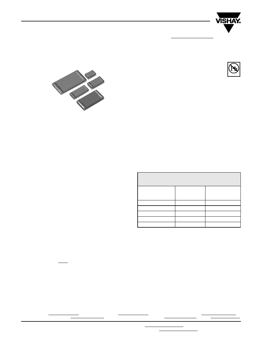
VFCP Series (0805, 1206, 1506, 2010, 2512)
Vishay Foil Resistors
Z Foil Flip Chip Resistor with TCR of ± 0.2 ppm/∞C
and 35% Space Saving versus Wrap Around Design
www.vishay.com
For technical questions in the Americas, contact: foilsupport1@vishay.com
Document Number: 63106
1
For technical questions in Asia/Japan/Europe/Africa/Israel, contact: foilsupport2@vishay.com
Revision: 18-Apr-06
SALES
∑ AMERICAS: foilsales.usa@vishay.com
∑ ASIA/JAPAN: foilsales.asia@vishay.com
∑ UK/HOLLAND/SCANDINAVIA: foilsales.eunorth@vishay.com
∑ GERMANY/CZECH REPUBLIC/AUSTRIA: foilsales.eucentral@vishay.com
∑ FRANCE/SWITZERLAND/SOUTHERN EUROPE: foilsales.eusouth@vishay.com
∑ ISRAEL: foilsales.israel@vishay.com
NEW PR
ODUCT
FEATURES
∑ TCR: ± 0.2 ppm/∞C typical (see Table 1)
∑ PCR (Power Coefficient of Resistance):
5 ppm at rated power
∑ Load Life Stability (70∞C for 2000 hours):
± 0.005%
∑ Power Rating to: 750 mW at + 70∞C
∑ Resistance Range: 10 to 150K (for lower and higher
values, please contact us)
∑ Tolerance: to ± 0.01%
∑ Shelf Life Stability: 0.005%
∑ Low Current Noise: - 40dB "Noise free component"
∑ Low Voltage Coefficient < 0.1 ppm/V
∑ Non Inductive: < 0.08µH
∑ Thermal EMF: < 0.05µV/∞C
∑ Terminal Finishes Available:
Lead (Pb)-Free (Sn 99.3% Cu 0.7%)
Tin/Lead Alloy (Sn 62% Pb 36% Ag 2%)
∑ Matched sets are available per request
Bottom View
INTRODUCTION
Bulk Metal
Æ
Foil (BMF) Technology out-performs all other
resistor technologies available today for applications that
require high precision and high stability.
This technology has been invented, patented and pioneered
by Vishay. Products based on this technology are the most
suitable for a wide range of analog applications.
BMF technology allows to produce customer oriented
products designed to satisfy challenging and specific
technical requirements.
One of the important parameters influencing stability is the
Temperature Coefficient of Resistance (TCR). Although the
TCR of Foil resistors is considered extremely low, this
characteristic has been further refined over the years.
The VFCP Series utilizes ultra precision Bulk Metal
Æ
Z-Foil
(BMZF).
The new Z-Foil technology provides a significant reduction of
the resistive element sensitivity to changes of temperature
due to ambient temperature variations (TCR) and to self
heating when power is applied (power coefficient).
The Z-Foil technology provides inherently an extremely low
and predictable Temperature Coefficient of Resistance
(TCR), a remarkably improved load life stability, low noise
and availability of tight tolerance.
The Flip Chip configuration provides a significant PCB space
saving of more than 35 % vs. the surface mount chip with
wrap-around terminations. The VFCP is available in any
value within the specified resistance range.
Our Application Engineering Department is available to
advise and make recommendations for non-standard
technical requirements and special applications, please
contact us.
**For Tighter performances, please contact Vishay Application
Engineering using the e-mail addresses in the footer below.
APPLICATIONS
∑ Automatic Test Equipment (ATE)
∑ High Precision Instrumentation
∑ Laboratory, Industrial and Medical
∑ Audio
∑ EB Applications (electron beam scanning and recording
equipment, electron microscopes)
∑ Military and Space
∑ Airborne
∑ Down Hole instrumentation
∑
Communication
TABLE 1 - TOLERANCE AND TCR VS
RESISTANCE VALUE**
RESISTANCE VALUE
(
)
TOLERANCE
(%)
TYPICAL TCR AND
MAX. SPREAD
(ppm/∞C)
250
to 150K
± 0.01
± 0.2 ± 1.6
100
to < 250
± 0.02
± 0.2 ± 1.6
50
to < 100
± 0.05
± 0.2 ± 1.8
25
to < 50
± 0.1
± 0.2 ± 2.8
10
to < 25
± 0.25
± 0.2 ± 2.8
* Pb containing terminations are not RoHS compliant, exemptions may apply
Available
Pb-free
RoHS*
COMPLIANT
Document Number: 63106
For technical questions in the Americas, contact: foilsupport1@vishay.com
www.vishay.com
Revision: 18-Apr-06
For technical questions in Asia/Japan/Europe/Africa/Israel, contact: foilsupport2@vishay.com
2
VFCP Series (0805, 1206, 1506, 2010, 2512)
Z Foil Flip Chip Resistor with TCR of ± 0.2 ppm/∞C
and 35% Space Saving versus Wrap Around Design
Vishay Foil Resistors
SALES
∑ AMERICAS: foilsales.usa@vishay.com
∑ ASIA/JAPAN: foilsales.asia@vishay.com
∑ UK/HOLLAND/SCANDINAVIA: foilsales.eunorth@vishay.com
∑ GERMANY/CZECH REPUBLIC/AUSTRIA: foilsales.eucentral@vishay.com
∑ FRANCE/SWITZERLAND/SOUTHERN EUROPE: foilsales.eusouth@vishay.com
∑ ISRAEL: foilsales.israel@vishay.com
NEW PR
ODUCT
(*)
VFCP2010 and VFCP2512 data are preliminary, for more details
please contact application engineering using the e-mail
addresses in the footer below.
Note: See table 1
TABLE 2 - LOAD LIFE STABILITY
(+70∞C FOR 2000 HOURS)
CHIP SIZE
MAXIMUM
R LIMITS
0805
± 0.005% at 50 mW
± 0.01% at 100 mW
1206
± 0.005% at 150 mW
± 0.01% at 250 mW
1506
± 0.005% at 150 mW
± 0.01% at 300 mW
2010
(*)
± 0.005% at 200mW
(*)
± 0.01% at 400 mW
(*)
2512
(*)
± 0.005% at 500 mW
(*)
± 0.01% at 750 mW
(*)
TABLE 3 - SPECIFICATIONS
CHIP SIZE
RATED
POWER (mW)
at +70∞C
RESISTANCE
RANGE (
)
MAXIMUM
WEIGHT (mg)
0805
100 mW
10
to 12K
5.2
1206
250 mW
10
to 30K
10.3
1506
300 mW
10
to 40K
12
2010
(*)
500 mW
(*)
10
to 100K
25
2512
(*)
750 mW
(*)
10
to 150K
35
**As shown + 0.01
to allow for measurement errors at low values.
***Land Pattern Dimensions are per IPC-782
TABLE 4 - ENVIRONMENTAL PERFORMANCE SPECIFICATIONS
TEST
MIL-PRF-55342 H
CHARACTERISTIC E
R LIMITS
VFCP
MAXIMUM
R LIMITS**
Thermal Shock
± 0.1%
± 0.01%
Low Temperature Operation
± 0.1%
± 0.01%
Short Time Overload
± 0.1%
± 0.01%
High Temperature Exposure
± 0.1%
± 0.02%
Resistance to Soldering Heat
± 0.2%
± 0.015%
Moisture Resistance
± 0.2%
± 0.02%
Load Life Stability +70∞C for 2000 hours
± 0.5%
± 0.01%
Maximum Working Voltage (V)
PxR
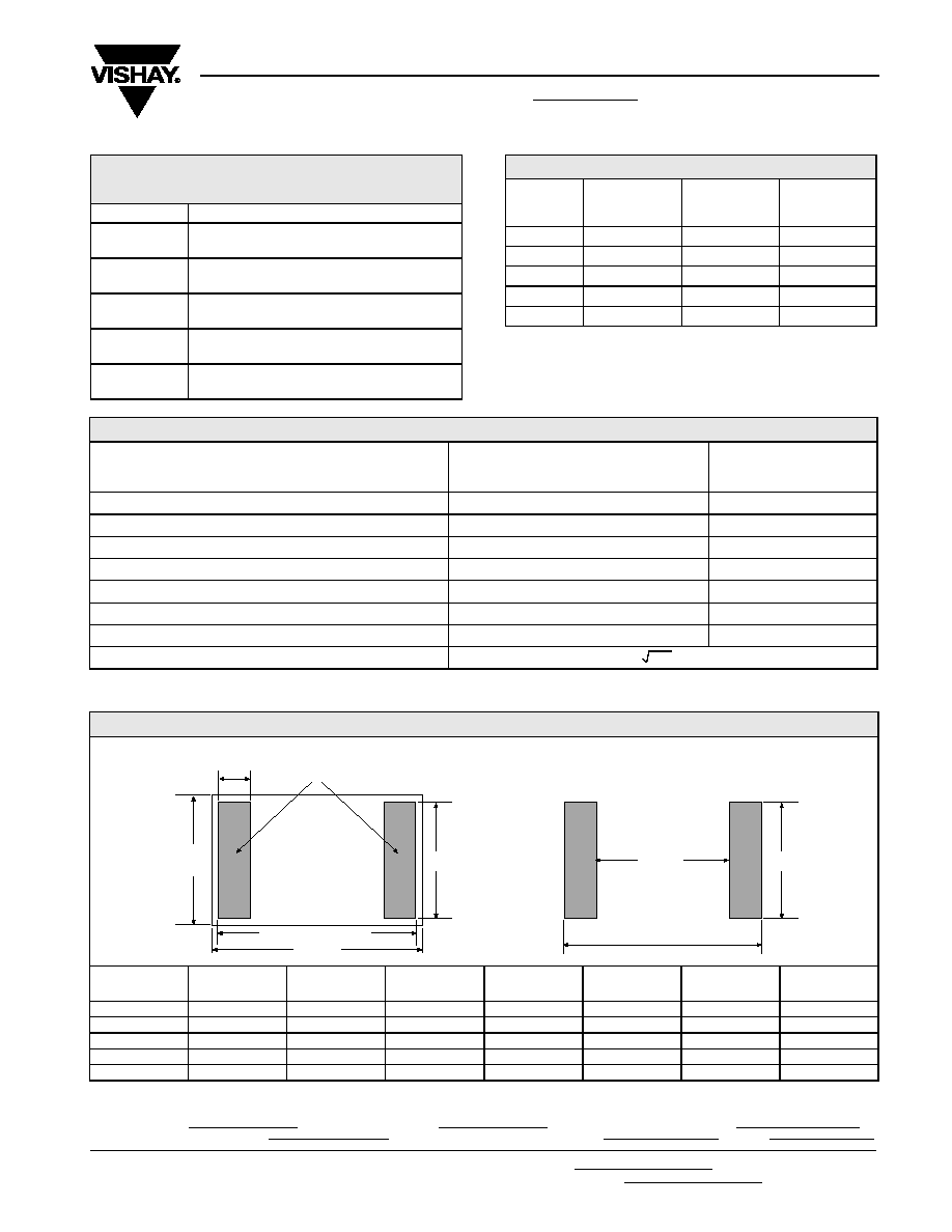
TABLE 5 - DIMENSIONS AND LAND PATTERN in inches (millimeters)
CHIP
SIZE
L
W
THICKNESS
D
Z***
G***
X***
± 0.005 (0.13)
± 0.005 (0.13)
MAXIMUM
± 0.005 (0.13)
MAXIMUM
MINIMUM
MAXIMUM
0805
0.079 (2.01)
0.049 (1.25)
0.025 (0.64)
0.010 (0.25)
0.078 (2.07)
0.053 (1.35)
0.049 (1.25)
1206
0.126 (3.20)
0.062 (1.57)
0.025 (0.64)
0.015 (0.38)
0.125 (3.20)
0.090 (2.29)
0.062 (1.57)
1506
0.150 (3.81)
0.062 (1.57)
0.025 (0.64)
0.012 (0.30)
0.150 (3.81)
0.120 (3.05)
0.062 (1.57)
2010
0.200 (5.08)
0.100 (2.54)
0.025 (0.64)
0.020 (0.51)
0.199 (5.05)
0.153 (3.84)
0.100 (2.54)
2512
0.250 (6.35)
0.126 (3.20)
0.025 (0.64)
0.024 (0.61)
0.250 (6.35)
0.196 (4.98)
0.126 (3.20)
D
W
L
L - 0.005 (0.13)
W1 [W - 0.003"]
Solder Terminals
BOTTOM VIEW (showing terminals for mounting)
LAND PATTERN
G
Z
X
VFCP Series (0805, 1206, 1506, 2010, 2512)
Vishay Foil Resistors
Z Foil Flip Chip Resistor with TCR of ± 0.2 ppm/∞C
and 35% Space Saving versus Wrap Around Design
www.vishay.com
For technical questions in the Americas, contact: foilsupport1@vishay.com
Document Number: 63106
3
For technical questions in Asia/Japan/Europe/Africa/Israel, contact: foilsupport2@vishay.com
Revision: 18-Apr-06
SALES
∑ AMERICAS: foilsales.usa@vishay.com
∑ ASIA/JAPAN: foilsales.asia@vishay.com
∑ UK/HOLLAND/SCANDINAVIA: foilsales.eunorth@vishay.com
∑ GERMANY/CZECH REPUBLIC/AUSTRIA: foilsales.eucentral@vishay.com
∑ FRANCE/SWITZERLAND/SOUTHERN EUROPE: foilsales.eusouth@vishay.com
∑ ISRAEL: foilsales.israel@vishay.com
NEW PR
ODUCT
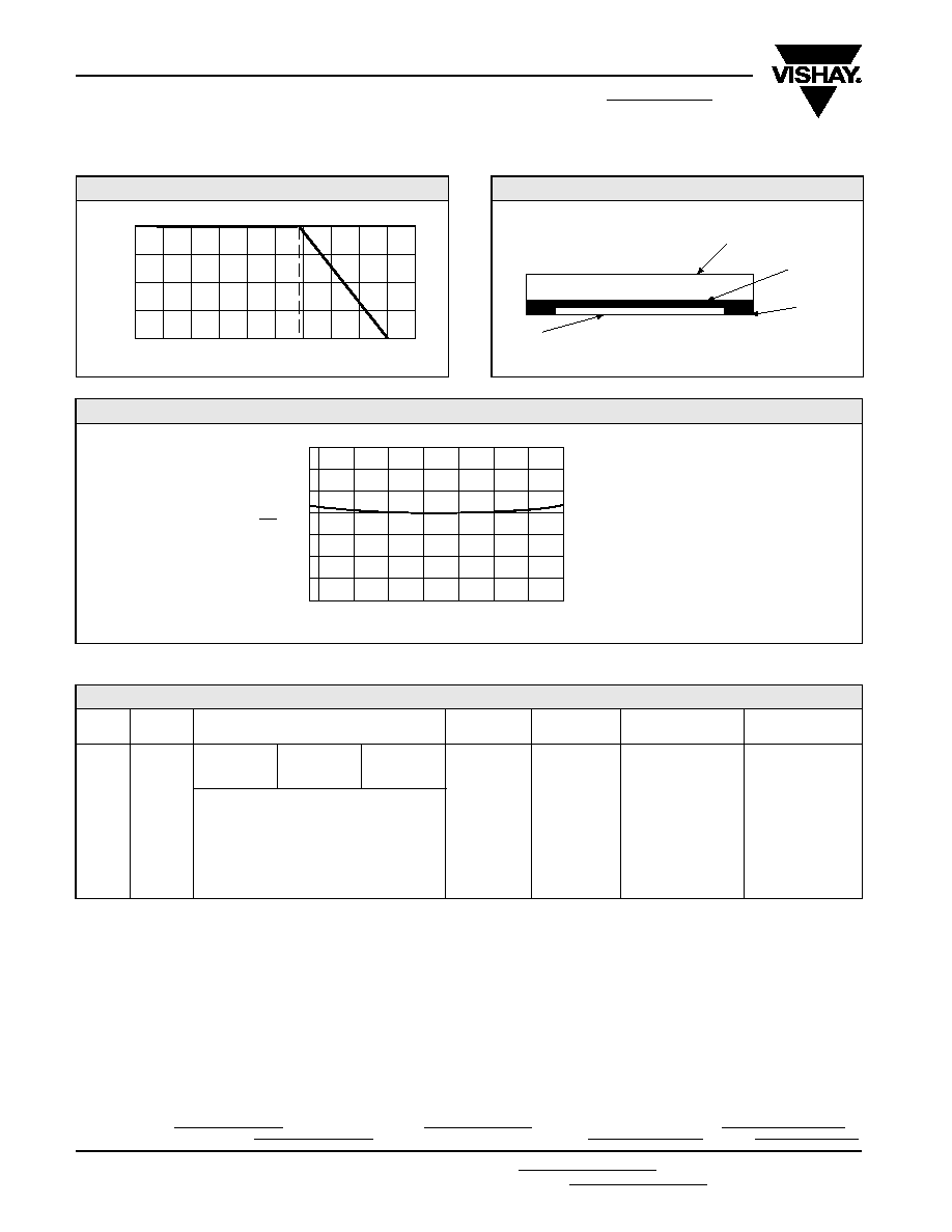
FIGURE 1 - POWER DERATING CURVE
100
75
50
25
0
-75
≠50
≠25
0
+25
+50
+75
+100 +125 +150 +175
Ambient Temperature (∞C)
Percent of
Rated
Po
w
er
+70
∞C
≠55
∞C
FIGURE 2 - CHIP CONFIGURATION
Protective Coating
High Purity Alumina Substrate
Resistive
Bulk
Æ
Metal Foil
Solder
Example:
VFCP0805 10K000 TCR0.2 TSW
Model: VFCP0805
Value: 10K
TCR0.2: 0.2 ppm/∞C typical refers to any value in the resistance range (see table 1)
Tolerance: ± 0.01%
Termination: Lead (Pb)-Free
Packaging: Waffle Pack
FIGURE 3 - TYPICAL TCR CURVE Z-FOIL (For more details, see Table 1)
Note: The TCR values for < 100
are influenced by the termination composition and result in deviation from this curve
TABLE 6 - ORDERING INFORMATION
MODEL
CHIP
SIZE
RESISTANCE VALUE
TCR
TOLERANCE
TERMINATION
PACKAGING
VFCP
0805
RESISTANCE
RANGE
LETTER
DESIGNATOR
MULTIPLIER
FACTOR
TCR0.2
T = 0.01%
S = Lead (Pb)-Free
T = Tape and Reel
1206
Q = 0.02%
B = Tin/Lead
W = Waffle Pack
1506
10
to < 1K
R
X 1.0
A = 0.05%
2010
Example: 249R00 = 249
B = 0.1%
2512
1K
to 150K
K
X 10
3
C = 0.25%
Example: 10K000 = 10.0K
D = 0.5%
F = 1.0%
+ 150
+ 100
+ 50
0
- 50
- 100
- 150
- 200
- 50
- 25
0
+
25
+ 50
+ 75
+ 100
+ 125
Ambient Te mperature (
∞C)
- 55
R
R
(ppm )
± 0.2 ppm/∞C (+25∞C reference)

Legal Disclaimer Notice
Vishay
Document Number: 91000
www.vishay.com
Revision: 08-Apr-05
1
Notice
Specifications of the products displayed herein are subject to change without notice. Vishay Intertechnology, Inc.,
or anyone on its behalf, assumes no responsibility or liability for any errors or inaccuracies.
Information contained herein is intended to provide a product description only. No license, express or implied, by
estoppel or otherwise, to any intellectual property rights is granted by this document. Except as provided in Vishay's
terms and conditions of sale for such products, Vishay assumes no liability whatsoever, and disclaims any express
or implied warranty, relating to sale and/or use of Vishay products including liability or warranties relating to fitness
for a particular purpose, merchantability, or infringement of any patent, copyright, or other intellectual property right.
The products shown herein are not designed for use in medical, life-saving, or life-sustaining applications.
Customers using or selling these products for use in such applications do so at their own risk and agree to fully
indemnify Vishay for any damages resulting from such improper use or sale.