www.vishay.com
99
VFP-3, VFP-4
Vishay Foil Resistors
Document Number: 63014
Revision 02-Mar-05
THROUGH HOLE
For technical questions in the Americas, contact foilsupport1@vishay.com
For technical questions in Asia/Japan/Europe/Africa/Israel, contact foilsupport2@vishay.com
∑ ISRAEL: foilsales.israel@vishay.com ∑ FRANCE/SWITZERLAND/SOUTHERN EUROPE: foilsales.eusouth@vishay.com ∑ AMERICAS: foilsales.usa@vishay.com
∑ ASIA/JAPAN: foilsales.asia@vishay.com ∑ UK/HOLLAND/SCANDINAVIA: foilsales.eunorth@vishay.com ∑ GERMANY/CZECH REPUBLIC/AUSTRIA: foilsales.eucentral@vishay.com
SALES
Bulk Metal
Æ
Foil Technology
Power and Current Sensing Resistors
FEATURES
∑ Temperature Coefficient of Resistance-- Nominal TCR
3
:
+ 0.6ppm/
∞
C (0
∞
C to + 25
∞
C); ≠ 0.6ppm/
∞
C (+ 25
∞
C to
+ 60
∞
C);
+ 2.2ppm/
∞
C (≠ 55
∞
C to + 25
∞
C); ≠ 1.8ppm/
∞
C (+ 25
∞
C to
+ 125
∞
C)
∑ Selected TCR Tracking: to 0.5ppm/
∞
C (matched sets)
∑ Power Rating: 10 W on heat sink at + 25
∞
C;
3W, free air at + 25
∞
C
∑ Load-Life Stability:
±
0.05% Maximum
R, 3 watts at + 25
∞
C
±
0.05% Maximum
R, 10 watts on heat sink at + 25
∞
C
∑ Resistance Tolerance:
±
0.01% tightest to
±
5.0% loosest
∑ Resistance Range: 0.05
to 80K
∑ Current Noise: < 0.010
µ
V (RMS)/Volt of Applied Voltage
∑ Thermal EMF: 0.1
µ
V/
∞
C Maximum; 0.05
µ
V/
∞
C Typical;
1
µ
V/watt
∑ Non-Inductive Design: Standard
∑ Shelf Life Stability: 25ppm/year
The basic features of Vishay Bulk Metal
Æ
Foil resistors; tight
resistance tolerance, fast response time, low TCR, and
exceptional long-term stability, are available for power-circuit
applications. Typical applications are non-inductive design,
current sensing applications, deflection amplifiers, constant
current power supplies, forced balance electronic scales,
graphic display computers, character generation on CRTs, and
electron beam controls.
RESISTANCE
STANDARD
TCR
RANGE (
)
RESISTANCE TOLERANCE
1
MAXIMUM
50 to 80K
±
0.01%
±
5ppm/
∞
C
25 to < 50
±
0.02%
±
7ppm/
∞
C
10 to < 25
±
0.05%
±
10ppm/
∞
C
5 to < 10
±
0.1%
±
13ppm/
∞
C
2 to < 5
±
0.25%
±
20ppm/
∞
C
1 to < 2
±
0.5%
±
25ppm/
∞
C
0.5 to < 1
±
1.0%
0.25 to < 0.5
±
2.0%
±
50ppm/
∞
C
0.1 to < 0.25
±
5.0%
TABLE 1 - VFP-3* SPECIFICATIONS
See last page in this data sheet for numbered footnotes.
*Weight = 15 grams Max
VFP-4 available only up to 500 ohms
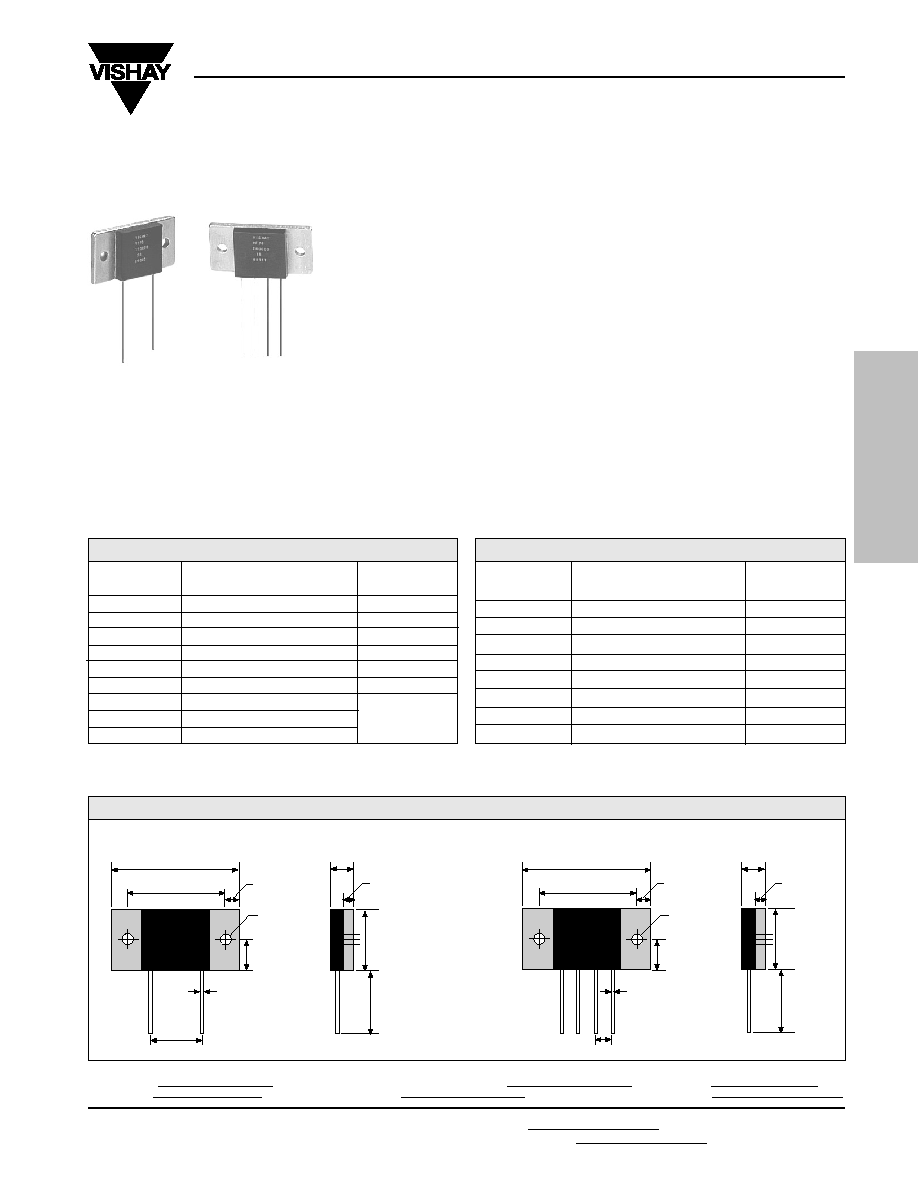
FIGURE 1 - STANDARD IMPRINTING AND DIMENSIONS
in inches (millimeters)
VFP-3
VFP-4
1.575
±
0.016 (40
±
0.4)
0.276
(7.0
)
1.181
±
0.016 (30
±
0.4)
1.181
±
0.016 (30
±
0.4)
E2
1.575
±
0.016 (40
±
0.4)
0.150
±
0.004
(3.8
±
0.1)
E1
I2
I1
0.197 (5)
0.197 (5)
0.150
±
0.004
(3.8
±
0.1)
0.394
±
0.008
(10
±
0.2)
0.394
±
0.008
(10
±
0.2)
Lead Dia.
0.025 (0.633)
Solder Coated
Copper
Lead Dia.
0.025 (0.633)
Solder Coated
Copper
0.600 (15.24)
0.200 [x3] (5.08)
0.118 (3)
0.118 (3)
0.787
±
0.016
(20
±
0.4)
0.787
±
0.016
(20
±
0.4)
1.00 Min.
(25.4 Min.)
1.00 Min.
(25.4 Min.)
0.276
(7.0
)
+0.004
+0.1
≠0.008
≠0.2
+0.004
+0.1
≠0.008
≠0.2
VISHAY
VFP-3
(Value)
(Tol.)
(Date Code)
VISHAY
VFP-4
(Value)
(Tol.)
(Date Code)
TABLE 2 - VFP-4*
SPECIFICATIONS
RESISTANCE
STANDARD
TCR
RANGE (
)
RESISTANCE TOLERANCE
1
MAXIMUM
10 to 500
±
0.01%
±
5ppm/
∞
C
5 to < 10
±
0.02%
±
6ppm/
∞
C
2 to < 5
±
0.05%
±
8ppm/
∞
C
1 to < 2
±
0.1%
±
10ppm/
∞
C
0.5 to < 1
±
0.25%
±
15ppm/
∞
C
0.25 to < 0.5
±
0.5%
±
20ppm/
∞
C
0.1 to < 0.25
±
1.0%
±
25ppm/
∞
C
0.05 to < 0.1
±
2.0%
±
30ppm/
∞
C
Product may not
be to scale

Document Number: 63014
Revision 02-Mar-05
www.vishay.com
100
VFP-3, VFP-4
Vishay Foil Resistors
THROUGH HOLE
For technical questions in the Americas, contact foilsupport1@vishay.com
For technical questions in Asia/Japan/Europe/Africa/Israel, contact foilsupport2@vishay.com
∑ ISRAEL: foilsales.israel@vishay.com ∑ FRANCE/SWITZERLAND/SOUTHERN EUROPE: foilsales.eusouth@vishay.com ∑ AMERICAS: foilsales.usa@vishay.com
∑ ASIA/JAPAN: foilsales.asia@vishay.com ∑ UK/HOLLAND/SCANDINAVIA: foilsales.eunorth@vishay.com ∑ GERMANY/CZECH REPUBLIC/AUSTRIA: foilsales.eucentral@vishay.com
SALES
Specify Vishay VFP-3 and VFP-4 resistors as follows:
Example:
VFP-3
21K500
0.01%
MODEL NO.
RESISTANCE VALUE
TOLERANCE
Resistance Value, in ohms, is expressed by a series of 6 characters, 5 of which represent significant digits while the 6th is a dual purpose
letter that designates both the multiplier and the location of the comma or decimal.
RESISTANCE
LETTER
MULTIPLIER
RANGE
DESIGNATOR
FACTOR
EXAMPLE
0.05
to < 1K
R
x1
100R01 = 100.01
1K
to 80K
K
x10
3
15K231 = 15,231
Stability
Load Life at 2,000 hrs.
Shelf Life
Power Rating
At + 25
∞
C
Current Noise
High Frequency Operation
Rise/Decay Time
Inductance (L)
7
Capacitance (C)
Voltage Coefficient
Operating Temp. Range
Maximum Working Voltage
9
Thermal EMF
10
±
0.05% Maximum
R under full rated power (3 W @+ 25
∞
C)
±
0.0025% (25ppm)
R/year
10 watts or 3 amps
5
on heat sink
6
3 watts or 3 amps
5
in free air
Power rating based on
R. Further derating not necessary.
< 0.010
µ
V (RMS)/Volt of applied voltage (≠ 40dB)
1.0ns at 1K
0.1
µ
H maximum; 0.08
µ
H typical
2
1.0pF maximum; 0.5pF typical
2
< 0.1ppm/V
8
≠ 55
∞
C to + 150
∞
C
350 V
0.5
µ
V/
∞
C Maximum (lead effect)
4.0
µ
V/watt (power effect)
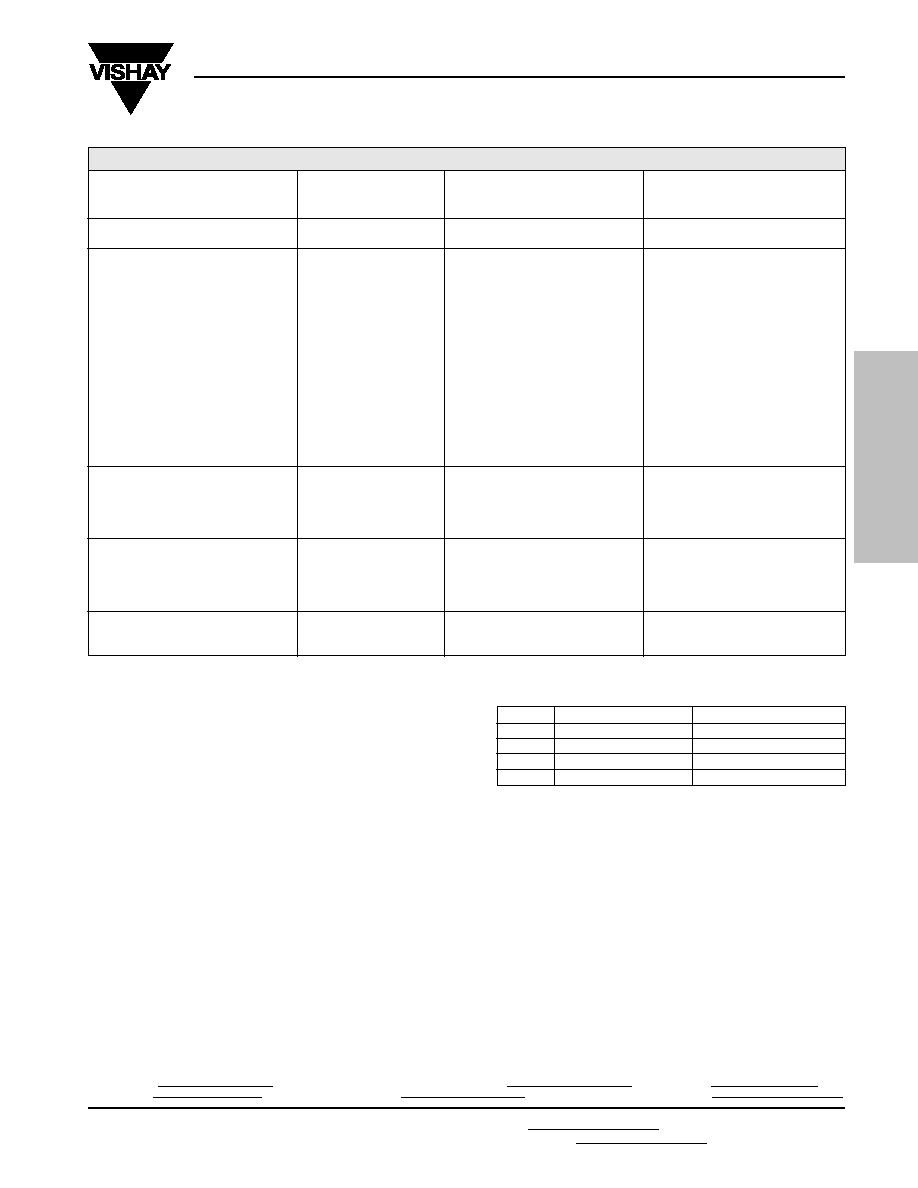
TABLE 3 - SPECIFICATIONS
2
FIGURE 2 - POWER DERATING CURVE
+100
+75
+50
+25
0
≠75 ≠50 ≠25 0 +25 +50 +75 +100 +125 +150 +175
Ambient Temperature (
∞
C)
Percent of Rated Power
≠55
∞
C
Rated Power
TABLE 4 - ORDERING INFORMATION
Bulk Metal
Æ
Foil Technology
Power and Current Sensing Resistors
www.vishay.com
101
VFP-3, VFP-4
Vishay Foil Resistors
Document Number: 63014
Revision 02-Mar-05
THROUGH HOLE
For technical questions in the Americas, contact foilsupport1@vishay.com
For technical questions in Asia/Japan/Europe/Africa/Israel, contact foilsupport2@vishay.com
∑ ISRAEL: foilsales.israel@vishay.com ∑ FRANCE/SWITZERLAND/SOUTHERN EUROPE: foilsales.eusouth@vishay.com ∑ AMERICAS: foilsales.usa@vishay.com
∑ ASIA/JAPAN: foilsales.asia@vishay.com ∑ UK/HOLLAND/SCANDINAVIA: foilsales.eunorth@vishay.com ∑ GERMANY/CZECH REPUBLIC/AUSTRIA: foilsales.eucentral@vishay.com
SALES
NOTES:
1. Standard resistance tolerances--
±
0.01%;
±
0.02%;
±
0.05%;
±
0.1%;
±
0.25%
±
0.5%;
±
1.0%;
±
2.0%;
±
5.0%
(Tighter tolerances available on request.)
2. Maximum is 1.0% A.Q.L. standard for all specifications
except TCR. (For TCR information, see notes 3-5). Typical
is a designers reference which represents that 85% of the
units supplied, over a long period of time, will be at least
the figure shown or better.
3. Vishay Nominal TCR is defined as the chord slopes of the
relative change of resistance/temperature, expressed in
ppm (parts per million), called (RT) curve from 0
∞
C to + 25
∞
C
and + 25
∞
C to + 60
∞
C ("Instrument" Range); and from
≠ 55
∞
C to + 25
∞
C and + 25
∞
C to + 125
∞
C ("Military" Range).
These specifications and the definition of Nominal TCR
apply to all resistance values including low-value resistors.
4. Vishay Maximum TCR Spread is defined as the 3
(Sigma)
limit of a normal Gaussian distribution (99.73% of a
production lot) which is within a band, centered on the
nominal curve. This Vishay Maximum TCR Spread is no
greater than
±
2.5ppm/
∞
C from nominal throughout the full
temperature range. This definition of the Vishay Maximum
TCR Spread from Nominal applies to all resistance values.
However, as the resistance value decreases below 80 ohms,
the Vishay maximum TCR Spread from Nominal specification
starts to increase. (See Fig. 3 in data sheet "7 Technical
Reasons to Specify BMF Resistive Components.")
5. Whichever is lower.
METHOD
MIL-R-39009B
VFP-3, VFP-4
PARAGRAPH
11
R LIMITS
MAXIMUM
2
TEST DATA
15
TEST GROUP I
Conditioning
4.7.2
±
0.2% + 0.05
±
0.03%
TEST GROUP II
Resistance Temperature Characteristic
12
4.7.4
< 1
:
±
100ppm/
∞
C;
See
(≠ 55
∞
C to + 125
∞
C)
1
to 19.6
:
±
50ppm/
∞
C;
Tables 1 & 2
20
:
±
30ppm/
∞
C
on Page 37
Temperature
13
(2 hours @ + 150
∞
C)
4.7.5
±
0.5% + 0.05
±
0.01%
Low Temp Storage
4.7.17
±
0.3% + 0.05
±
0.01%
DWV
(750V @ atmosphere pressure)
4.7.6
±
0.2% + 0.05
±
0.005%
Insulation Resistance
4.7.7
10
4
M
> 10
4
M
Low Temp Operation
4.7.8
±
0.3% + 0.05
±
0.01%
Momentary Overload
14
(5 seconds @ 750 V rms)
4.7.9
±
0.3% + 0.05
±
0.01%
Moisture Resistance
4.7.10
±
0.5% + 0.05
±
0.05%
Terminal Strength
4.7.11
±
0.2% + 0.05
±
0.005%
TEST GROUP III
Shock - Medium Impact
(Post-test DWV @ 750 V)
4.7.12
±
0.2% + 0.05
±
0.005%
Vibration - High Frequency
(Post-test DWV @ 750 V)
4.7.13
±
0.2% + 0.05
±
0.005%
TEST GROUP IV
Life Test
10 W @ + 25
∞
C for 2,000 hrs.
4.7.14
±
1.0% + 0.05
±
0.05%
60% power @ + 70
∞
C
for 2,000 hours
≠≠≠
≠≠≠
±
0.05%
TEST GROUP V
High Temp Exposure
(2,000 hours. @ + 150
∞
C)
4.7.15
±
1.0% + 0.05
±
0.03%
TABLE 5 - POWER RESISTOR ENVIRONMENTAL PERFORMANCE COMPARISON
6. Heat sink chassis dimensions and requirements per
MIL-R-39009/1B:
INCHES
MILLIMETERS
L
6.00
152.4
W
4.00
101.6
H
2.00
50.8
T
0.04
1.0
7. Inductance (L) due mainly to the leads.
8. The resolution limit of existing test equipment (within the
measurement capability of the equipment, or "essentially
zero").
9. Not to exceed power rating of resistor.
10.
µ
V/
∞
C relates to EMF due to lead temperature difference
and
µ
V/watt due to power applied to the resistor.
11. Vishay test data as compared to MIL-R-39009 is shown
for illustration purposes. Vishay test conditions that deviate
from the Mil test method are noted within parentheses.
12. Maximum specifications. See Tables 1 and 2 on first page
in this data sheet.
13. Maximum ambient temperature rating is + 150
∞
C.
14. Maximum overload rating is 15 Watts (5 x rated power in
free air; 1.5 x rated power on heat sink), with applied
voltage not to exceed 750V.
15.
Rs are as shown plus 0.001 ohms to allow for measurement
errors at low resistance values.
Bulk Metal
Æ
Foil Technology
Power and Current Sensing Resistors