Document Number: 63009
Revision 23-May-06
www.vishay.com
136
VSR Series
Vishay Foil Resistors
THROUGH HOLE
For technical questions, contact: foil@vishay.com
SALES
∑ AMERICAS: foilsales.usa@vishay.com ∑ ASIA/JAPAN: foilsales.asia@vishay.com ∑ UK/HOLLAND/SCANDINAVIA: foilsales.eunorth@vishay.com
∑ GERMANY/CZECH REPUBLIC/AUSTRIA: foilsales.eucentral@vishay.com ∑ FRANCE/SWITZERLAND/SOUTHERN EUROPE: foilsales.eusouth@vishay.com ∑ ISRAEL: foilsales.israel@vishay.com
Bulk Metal
Æ
Foil Technology Industrial Precision Resistors
with TCR of
±
4ppm/
∞
C, Tolerance of
±
0.01%
INTRODUCTION
Bulk Metal
Æ
Foil Technology out performs all other resistor
technologies available today for applications that require high
precision and high stability.
This technology has been pioneered and developed by
VISHAY, and products based on this technology are the most
suitable for a wide range of applications.
Generally Bulk Metal
Æ
Foil technology allows us to produce
customer orientated products designed to satisfy challenging
and specific technical requirements.
The VSR series of resistors is a low cost version of the well
established S-Series of resistors. These resistors are made
of foil elements so all of the inherent performance of foil is
retained. They do not however, have the same TCR or
tolerance ranges (see table 1 for details). These products find
a wide range of usage in high end stereo equipment and some
grades of test and measurement equipment.
Standoffs are dimensioned to provide a minimum lead
clearance of 0.010 inches between the resistor body and the
printed circuit board, when the standoffs are seated on the
board. This allows for proper cleaning after the soldering
process**.
Our Applications Engineering Department is available to
advise and to make recommendations for non standard
technical requirements and special applications, please
contact us.
FEATURES
∑ Temperature Coefficient of Resistance (TCR)*:
±
4ppm/
∞
C (0
∞
C to + 60
∞
C, + 25
∞
C Ref.)
±
8ppm/
∞
C (- 55
∞
C to + 125
∞
C, + 25
∞
C Ref.)
∑ Resistance Range: 0.5
to 1M
(higher or lower values
of resistance are available)
∑ Resistance Tolerance: to
±
0.01%
∑ Long Term Stability: Typical Foil Performance
∑ Very Low Current Noise: - 40dB
∑ Low Inductance: 0.08
µ
H
∑ Thermal EMF: 0.05
µ
V/
∞
C
∑ Voltage Coefficient: < 0.1ppm/V
∑ Matched Sets Available
∑ Terminal Finishes Available:
Lead (Pb)-free (100% Sn)
Tin/Lead Alloy (Sn 60%, Pb 40%)
∑ For better performances please review the S Series datasheet
* For values below 50
please contact Application Engineering
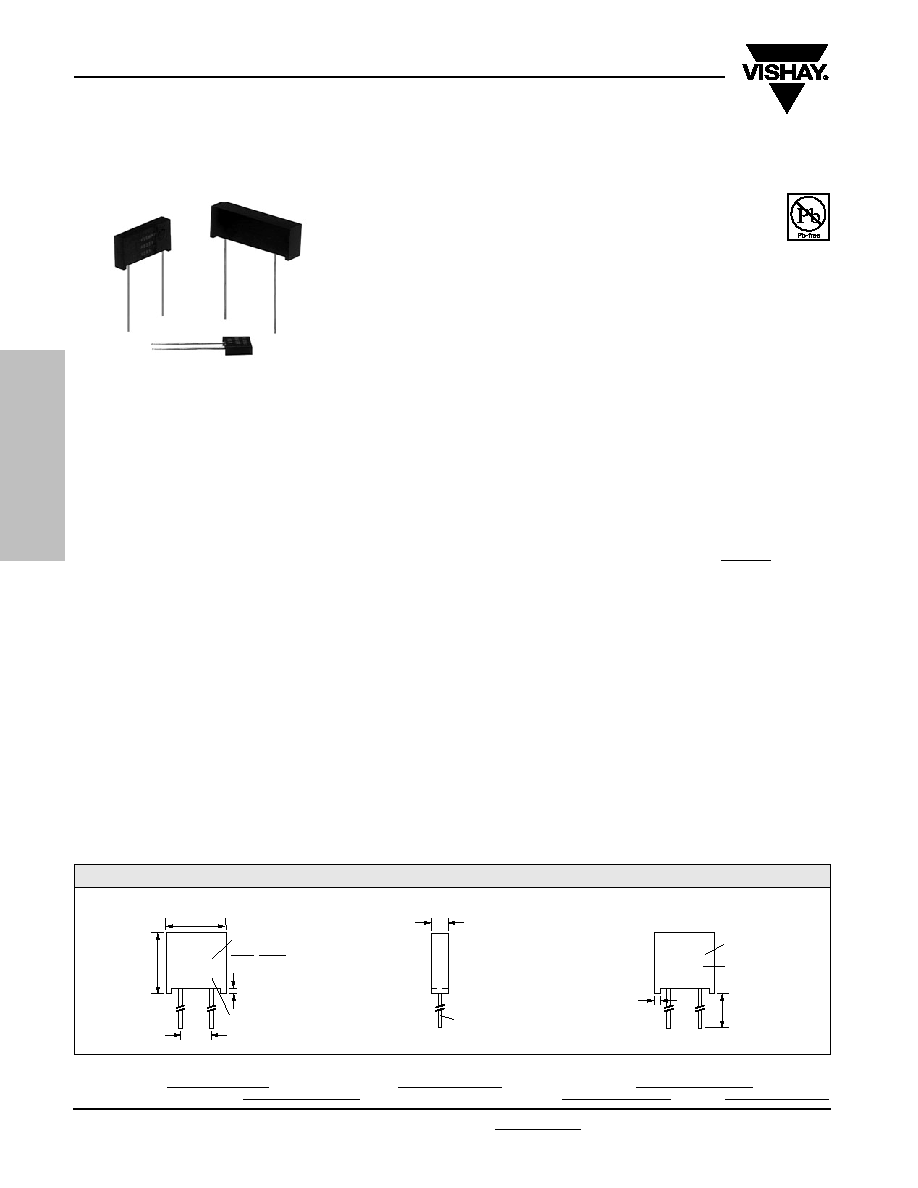
FIGURE 1 - IMPRINTING AND DIMENSIONS
APPLICATIONS
∑ Industrial
∑ Medical
∑ Audio (high end stereo equipment)
∑ Test and Measurement equipment
∑ Precision Amplifiers
LS
Model Number
VISHAY
XXXX
VSR4
ST
**
H
L
Date Code
W
Front View
Lead Material #22 AWG
Round Solder Coated Copper
10
Week
01
Year
Rear View
Resistance
Value Code
Tolerance
100R01
0.01%
LL
SW
Any value at any tolerance
available within resistance range
RoHS
COMPLIANT

www.vishay.com
137
VSR Series
Vishay Foil Resistors
Document Number: 63009
Revision 23-May-06
THROUGH HOLE
For technical questions, contact: foil@vishay.com
SALES
∑ AMERICAS: foilsales.usa@vishay.com ∑ ASIA/JAPAN: foilsales.asia@vishay.com ∑ UK/HOLLAND/SCANDINAVIA: foilsales.eunorth@vishay.com
∑ GERMANY/CZECH REPUBLIC/AUSTRIA: foilsales.eucentral@vishay.com ∑ FRANCE/SWITZERLAND/SOUTHERN EUROPE: foilsales.eusouth@vishay.com ∑ ISRAEL: foilsales.israel@vishay.com
MAXIMUM
POWER
POWER
MAXIMUM
SHELF LIFE LOAD LIFE TEMPERATURE COEFFICIENT
MODEL
RESISTANCE
AT
AT
WORKING
STABILITY STABILITY
OF RESISTANCE
NUMBER
(
)
+70
∞
C
+125
∞
C
VOLTAGE
(MAXIMUM
R) (MAXIMUM
R)
(+ 25
∞
C Ref.)
VSR
1 to 150K
0.3W
0.2W
300
up to 100K
VSRJ*
0.25W
0.15W
(0.20 LS)
over 100K
VSR4
1 to 500K
0.5W
0.4W
350
up to 200K
0.25W
0.2W
over 200K
VSR5
1 to 750K
0.75W
0.6W
350
up to 300K
0.4W
0.3W
over 300K
VSR6
0.5 to 1M
1.0W
0.8W
500
up to 400K
0.5W
0.4W
over 400K
TABLE 1 - MODEL SELECTION
TIGHTEST TOLERANCE%
VS. LOWEST
RESISTANCE VALUE
±
0.01 / 25
±
0.02 / 12
±
0.05 / 5
±
0.5 / 1
±
1 / 0.5
* 0.200 inches (5.08 mm) lead spacing available-- specify VSRJ. Note Minor Outline Dimension Variations:
INCHES
mm
W:
0.098 Maximum
2.49 Maximum
L:
0.295 Maximum
7.49 Maximum
H:
0.315 Maximum
8.00 Maximum
ST:
0.015
±
0.0015
0.381
±
0.038
LL:
1.000
±
0.125
25.4
±
0.318
LS:
0.200
±
0.003
5.08
±
0.076
25 ppm
0.05%
0
∞
C to + 60
∞
C
after
2,000 hours
±
4 ppm/
∞
C
1 year
@ + 125
∞
C
- 55
∞
C to + 125
∞
C
±
8 ppm/
∞
C
DIMENSIONS
Inches
m m
W: 0.105
±
0.010
2.67
±
0.25
L: 0.300
±
0.010
7.62
±
0.25
H: 0.326
±
0.010
8.28
±
0.25
ST: 0.010 Minimum 0.254 Minimum
SW: 0.040
±
0.005
1.02
±
0.13
LL: 1.000
±
0.125
25.4
±
3.18
LS: 0.150
±
0.005*
3.81
±
0.13
W: 0.160 Maximum 4.06 Maximum
L: 0.575 Maximum 14.61 Maximum
H: 0.413 Maximum 10.49 Maximum
ST: 0.035
±
0.005
0.889
±
0.13
SW: 0.050
±
0.005
1.27
±
0.13
LL: 1.000
±
0.125
25.4
±
3.18
LS: 0.400
±
0.020
10.16
±
0.51
W: 0.160 Maximum 4.06 Maximum
L: 0.820 Maximum 20.83 Maximum
H: 0.413 Maximum 10.49 Maximum
ST: 0.035
±
0.005
0.889
±
0.13
SW: 0.050
±
0.005
1.27
±
0.13
LL: 1.000
±
0.125
25.4
±
3.18
LS: 0.650
±
0.020
16.51
±
0.51
W: 0.260 Maximum 6.60 Maximum
L: 1.200 Maximum 30.48 Maximum
H: 0.413 Maximum 10.49 Maximum
ST: 0.035
±
0.005
0.889
±
0.13
SW: 0.050
±
0.005
1.27
±
0.13
LL: 1.000
±
0.125
25.4
±
3.18
LS: 0.900
±
0.020
22.86
±
0.51
Please specify Vishay "VSR" Series as follows:
T =
±
0.01%
Q =
±
0.02%
Example:
A =
±
0.05%
B =
±
0.1%
C =
±
0.25%
T = Lead (Pb)-free,
D =
±
0.5%
VSR
(none) = Tin/Lead Alloy
100R01
F =
±
1%
MODEL NO.
TERMINATION
RESISTANCE VALUE
TOLERANCE
Resistance Value, in ohms, is expressed by a series of 6 characters, 5 of which represent significant digits while the 6th is a dual purpose
letter that designates both the multiplier and the location of the comma or decimal.
RESISTANCE
LETTER
MULTIPLIER
RANGE
DESIGNATOR
FACTOR
EXAMPLE
0.5
to < 1K
R
x 1
100R01 = 100.01
1K
to < 1M
K
x 10
3
15K231 = 15,231
1M
M
x 10
6
1M0000 = 1,000,000
For example: VSRT100K00D - Model: VSR; Termination: Lead (Pb)-free; Value: 100K
; Tolerance: 0.5%.
TABLE 2 - ORDERING INFORMATION

Legal Disclaimer Notice
Vishay
Document Number: 91000
www.vishay.com
Revision: 08-Apr-05
1
Notice
Specifications of the products displayed herein are subject to change without notice. Vishay Intertechnology, Inc.,
or anyone on its behalf, assumes no responsibility or liability for any errors or inaccuracies.
Information contained herein is intended to provide a product description only. No license, express or implied, by
estoppel or otherwise, to any intellectual property rights is granted by this document. Except as provided in Vishay's
terms and conditions of sale for such products, Vishay assumes no liability whatsoever, and disclaims any express
or implied warranty, relating to sale and/or use of Vishay products including liability or warranties relating to fitness
for a particular purpose, merchantability, or infringement of any patent, copyright, or other intellectual property right.
The products shown herein are not designed for use in medical, life-saving, or life-sustaining applications.
Customers using or selling these products for use in such applications do so at their own risk and agree to fully
indemnify Vishay for any damages resulting from such improper use or sale.