Document Number: 60083
Revision 06-Aug-02
www.vishay.com
176
VTSRC, VSSRC, VSORC-AA
Vishay Thin Film
RC NETWORKS
VISHAY THIN FILM ∑ FRANCE +33.4.93.37.28.24 FAX: +33.4.93.37.27.31 ∑ GERMANY +49.9287.710 FAX: +49 9287.70435 ∑ ISRAEL +972.3.557.0945 FAX: +972.3.558.9121
∑ ITALY + 39.2.300.11919 FAX: +39.2.300.11999 ∑ JAPAN +81.42.729.0661 FAX: +81.42.729.3400 ∑ SINGAPORE +65.788.6668 FAX: +65.788.0988
∑ SWEDEN +46.8.594.70590 FAX: +46.8.594.70581 ∑ UK +44 191 514 8237 FAX: +44 1953 457 722 ∑ USA: (610) 407-4800 FAX: (610) 640-9081
FEATURES
∑ Resistors and capacitors on a single chip
∑ Saves board space
∑ Reduces total assembly costs
∑ Uniform performance characteristics
∑ Compatible with automatic surface mounting equipment
∑ UL 94V-0 flame resistant
∑ Rugged, molded case construction
Actual Size
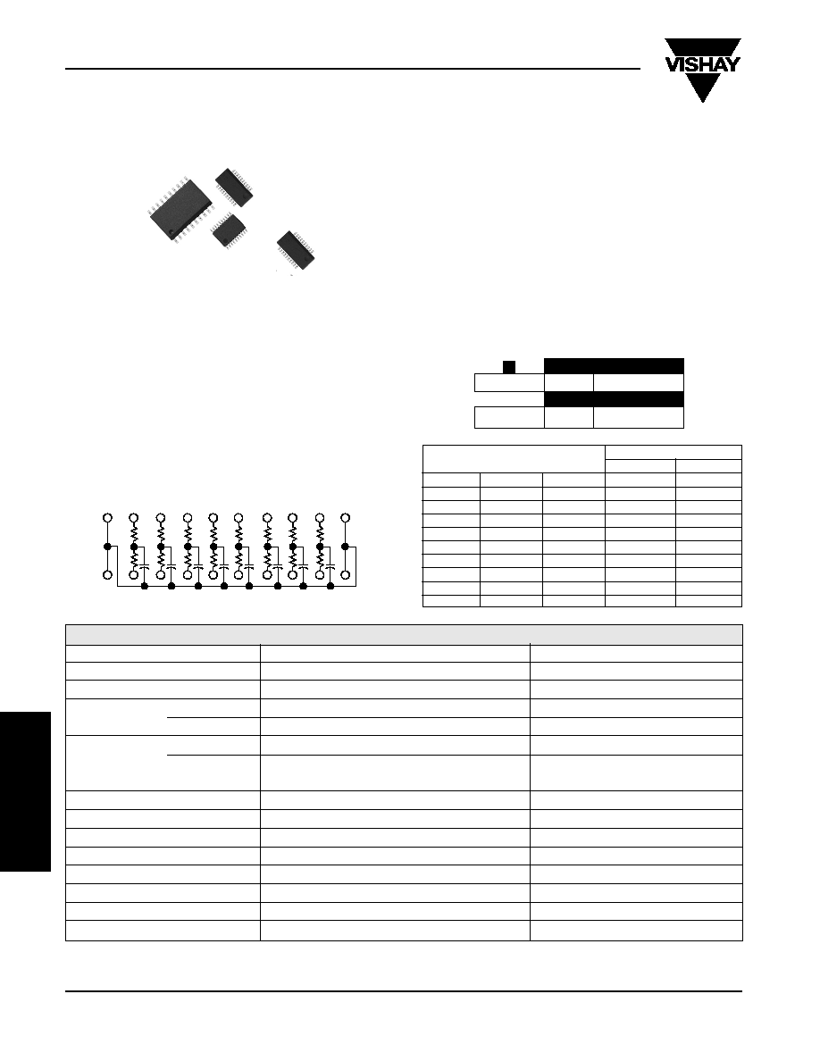
SCHEMATIC AA
Vishay Thin Film's T filter network is an integrated thin film
network on a single die. Noise suppression is at a maximum
with the use of thin film technology. The T filter network,
schematic AA is designed to suppress EMI/RFI noise with
such applications as I/O ports of personal computers and
peripherals, workstations and Local Area Networks. With a
rugged molded case to protect the circuit from the
environment and an integrated thin film network this product
is your choice when reduced size, improved accuracy and
surface mount capability are your goals.
Available packages SOIC, SSOP and TSSOP.
TEST
SPECIFICATIONS
CONDITIONS
MATERIAL
TANTALUM NITRIDE ON SILICON
Resistance Range
10 ohms to 750 ohm
TCR:
Tracking
±
10ppm/
∞
C
Absolute
±
200ppm/
∞
C
0
∞
C to + 70
∞
C
Tolerance:
Absolute
±
10% standard (R)
Absolute
±
20% standard (C)
@ 1MHz & VRMS over
+ 10
∞
C to + 70
∞
C
Power Rating:
Package
1W - (T)SSOP 1.2W - SOIC
See Derating Curve
Capacitance Range
10pF to 150pF - (T)SSOP/10pF to 250pF - SOIC
Stability (
R Ratio)
±
2%
1000 hrs.
ESD Protection
> 2kV
MIL-STD-883, Method 3015
Breakdown Voltage
35 - 50V
Operating Temperature Range
0 to + 70
∞
C
Storage Temperature Range
- 55
∞
C to + 125
∞
C
Power Rating/Resistor
100mW
20 19 18 17 16 15 14 13 12 11
1 2 3 4 5 6 7 8 9 10
25 or 50 Mil Pitch, T-Filter Resistor/Capacitor Networks
STANDARD VALUES
MODELS
VSORC
VSSRC
VTSRC
R (Ohms)
C (pF)
X
10
47
X
X
10
100
X
X
15
47
X
25
50
X
X
25
150
X
X
X
25
200
X
X
X
47
33
X
X
50
100
X
100
33
X
100
390
STANDARD ELECTRICAL SPECIFICATIONS
TCR
TOLERANCE
RESISTOR
200
10%
TCC
TOLERANCE
CAPACITOR
200
20%
TYPICAL PERFORMANCE
Small Outline, Surface Mount,
EMI/RFI Reduction
www.vishay.com
177
VTSRC, VSSRC, VSORC-AA
Vishay Thin Film
Document Number: 60083
Revision 06-Aug-02
RC NETWORKS
VISHAY THIN FILM ∑ FRANCE +33.4.93.37.28.24 FAX: +33.4.93.37.27.31 ∑ GERMANY +49.9287.710 FAX: +49 9287.70435 ∑ ISRAEL +972.3.557.0945 FAX: +972.3.558.9121
∑ ITALY + 39.2.300.11919 FAX: +39.2.300.11999 ∑ JAPAN +81.42.729.0661 FAX: +81.42.729.3400 ∑ SINGAPORE +65.788.6668 FAX: +65.788.0988
∑ SWEDEN +46.8.594.70590 FAX: +46.8.594.70581 ∑ UK +44 191 514 8237 FAX: +44 1953 457 722 ∑ USA: (610) 407-4800 FAX: (610) 640-9081
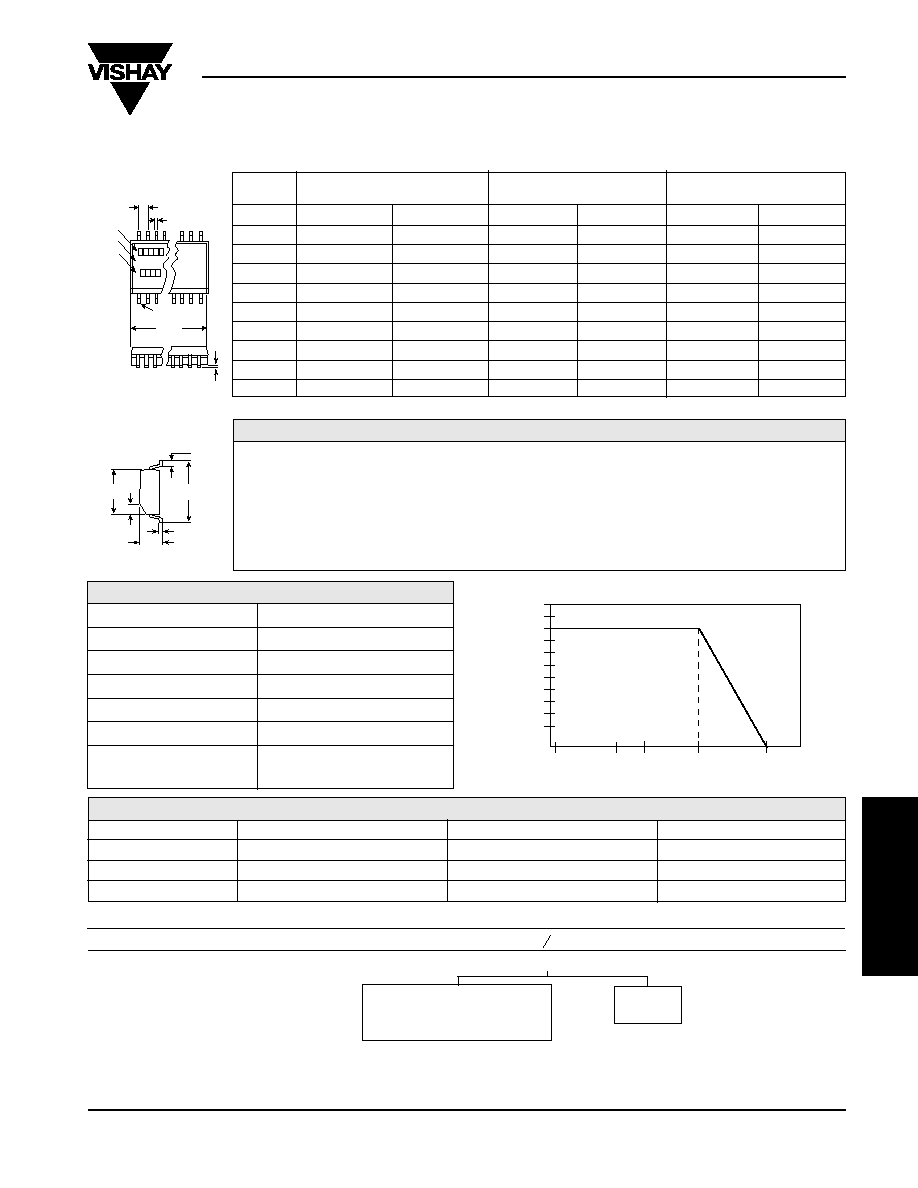
DIMENSIONS AND IMPRINTING
in inches and millimeters
B
C
Pin #1
Model
Date
Code
D
A
RES/CAP
x x x x x
xxx/xxx
x x x x
E
H
J
G
F
W
RES/CAP
NOTE: Mold flash not included in body dimensions.
25 or 50 Mil Pitch, T-Filter R/C Networks
MODEL
VTSRC20-AA
VSSRC20-AA
VSORC20-AA
INCHES
MILLIMETERS
INCHES
MILLIMETERS
INCHES
MILLIMETERS
A
0.256
±
0.003
6.5
±
0.08
0.351 Max.
8.91 Max.
0.500
±
0.010
12.7
±
0.25
B (Ref.)
0.025
0.65
0.025
0.64
0.050
1.27
C (Ref.)
0.0087
0.22
0.010
0.25
0.016
0.41
D
0.004
0.10
0.006
0.15
0.008
0.20
E (Typ.)
0.024
0.61
0.025
0.64
0.030
0.76
F
0.173
±
0.003
4.39
±
0.08
0.154
±
0.003
3.9
0.293
±
0.003
7.44
G
0.015 x 45
∞
0.38
0.015 x 45
∞
0.38
0.025 x 45
∞
0.64
H
0.252
±
0.005
6.4
±
0.13
0.236
±
0.008
6.0
±
0.20
0.406
±
0.005
10.31
J (Ref.)
0.005
0.13
0.010
0.25
0.010
0.25
W
0.043
±
0.005
1.09
±
0.13
0.064
±
0.005
1.6
0.100
±
0.005
2.59
MODEL
LEADS
TAPE AND REEL
TUBES
VTSRC (TSSOP)
20
2,500
74
VSSRC (SSOP)
20
2,500
55
VSORC (SOIC)
20
1,000
38
PACKING
IMPRINTING
VSORC, VSSRC, VTSRC
20
AA
XXX / XXX
MODEL
PIN COUNT
SCHEMATIC
RESISTANCE / CAPACITANCE
Code: e.g.
Code: e.g.
100 = 10 ohm
101 = 100pF
XXXX
Date Code
*Optional marking
DERATING CURVE
100
80
60
40
20
0
-50
0 25
70
125
150
Percent of Rated Power
Ambient Temperature
∞
C
Resistive Element
Tantalum Nitride
Substrate Material
Silicon
Body
Molded Epoxy
Terminals
Copper Alloy
Plating
Tin Lead
Lead Coplanarity
0.0005 Inches
Marking Resistance
Permanency testing per
to Solvents
MIL-STD-202, Method 215
MECHANICAL SPECIFICATIONS
How to Order
MODEL
Number of LeadsSchematic
Resistance Value (Code
) Capacitor Tolerance (Code pF)
Packaging
VTSRC
20
AA xxxK / xxxM Tape & Reel
VSSRC
20
AA
or Tubes
VSORC
20
AA
First 2 digits are significant
K =10%
figures. Last digit specifies
M = 20%
number of zeros to follow.