1
White Electronic Designs Corporation ∑ (602) 437-1520 ∑ www.whiteedc.com
EDI9LC644V
January 2002 Rev. 4
ECO# 14667
DESCRIPTION
The EDI9LC644VxxBC is a 3.3V, 128K x 32 Synchronous
Pipeline SRAM and a 1Mx32 Synchronous DRAM array con-
structed with one 128K x 32 SBSRAM and two 1Mx16
SDRAM die mounted on a multilayer laminate substrate. The
device is packaged in a 153 lead, 14mm by 22mm, BGA.
The EDI9LC644VxxBC provides a total memory solution for
t h e Te x a s I n s t r u m e n t s T M S 3 2 0 C 6 2 0 1 a n d t h e
TMS320C6701 DSPs
The Synchronous Pipeline SRAM is available with clock
speeds of 200, 166,150, and 133 MHz, allowing the user
to develop a fast external memory for the SSRAM inter-
face por t .
The SDRAM is available in clock speeds of 125 and 100
MHz, allowing the user to develop a fast external memory
for the SDRAM interface por t .
128Kx32 SSRAM/1Mx32 SDRAM
EXTERNAL MEMORY SOLUTION FOR TEXAS INSTRUMENTS TMS320C6000 DSP
FEATURES
n
Clock speeds:
∑ SSRAM: 200, 166,150, and 133 MHz
∑ SDRAMs: 125 and 100 MHz
n
DSP Memory Solution
∑ Texas Instruments TMS320C6201
∑ Texas Instruments TMS320C6701
n
Packaging:
∑ 153 pin BGA , JEDEC MO-163
n
3.3V Operating supply voltage
n
Direct control interface to both the SSRAM and SDRAM
ports on the "C6x"
n
Common address and databus
n
65% space savings vs. monolithic solution
n
Reduced system inductance and capacitance
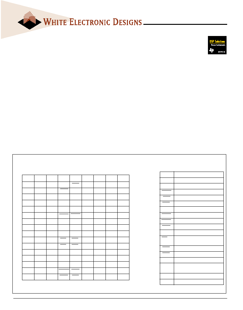
FIG. 1 PIN CONFIGURATION
1
2
3
4
5
6
7
8
9
A DQ
19
DQ
23
V
CC
V
SS
V
SS
V
SS
V
CC
DQ
24
DQ
28
A
B DQ
18
DQ
22
V
CC
V
SS
SDCE
V
SS
V
CC
DQ
25
DQ
29
B
C V
CCQ
V
CCQ
V
CC
SDWE SDA
10
NC
V
CC
V
CCQ
V
CCQ
C
D DQ
17
DQ
21
V
CC
V
SS
V
SS
V
SS
V
CC
DQ
26
DQ
30
D
E DQ
16
DQ
20
V
CC
V
SS
SDCLK
V
SS
V
CC
DQ
27
DQ
31
E
F V
CCQ
V
CCQ
V
CC
V
SS
V
SS
V
SS
V
CC
V
CCQ
V
CCQ
F
G NC
NC
NC
SDRAS SDCAS
V
SS
A
2
A
4
A
5
G
H NC
NC
A
8
V
SS
V
SS
NC
A
1
A
3
A
10
H
J
A6
A7
A9
VSS
VSS
NC
A0
A11
A12
J
K NC/A
17
NC/A
18
NC/A
19
V
SS
V
SS
NC
NC
A
13
A
14
K
L
NC
NC
NC
BWE
2
BWE
3
NC
NC
A
15
A
16
L
M V
CCQ
V
CCQ
V
CC
BWE
0
BWE
1
NC
V
CC
V
CCQ
V
CCQ
M
N DQ
12
DQ
11
V
CC
V
SS
V
SS
V
SS
V
CC
DQ
4
DQ
0
N
P DQ
13
DQ
10
V
CC
V
SS
SSCLK
V
SS
V
CC
DQ
5
DQ
1
P
R V
CCQ
V
CCQ
V
CC
V
SS
V
SS
V
SS
V
CC
V
CCQ
V
CCQ
R
T DQ
14
DQ
9
V
CC
SSADC SSWE
NC
V
CC
DQ
6
DQ
2
T
U DQ
15
DQ
8
V
CC
SSOE
SSCE
NC
V
CC
DQ
7
DQ
3
U
1
2
3
4
5
6
7
8
9
BOTTOM VIEW
A
0-16
Address Bus
DQ
0-31
Data Bus
SSCLK
SSRAM Clock
SSADC
SSRAM Address Status Control
SSWE
SSRAM Write Enable
SSOE
SSRAM Output Enable
SDCLK
SDRAM Clock
SDRAS
SDRAM Row Address Strobe
SDCAS
SDRAM Column Address Strobe
SDWE
SDRAM Write Enable
SDA
10
SDRAM Address 10/auto precharge
BWE
0-3
SSRAM Byte Write Enables
SDRAM SDQM 0 - 3
SSCE
Chip Enable SSRAM Device
SDCE
Chip Enable SDRAM Device
V
CC
Power Supply pins, 3.3V
V
CCQ
Data Bus Power Supply pins,
3.3V (2.5V future)
V
SS
Ground
NC
No Connect
P
IN
D
ESCRIPTION

2
White Electronic Designs Corporation ∑ Phoenix AZ ∑ (602) 437-1520
EDI9LC644V
FIG. 2
BLOCK DIAGRAM

3
White Electronic Designs Corporation ∑ (602) 437-1520 ∑ www.whiteedc.com
EDI9LC644V
OUTPUT FUNCTIONAL DESCRIPTIONS
Symbol
Type
Signal
Polarity
Function
SSCLK
Input
Pulse
Positive Edge The system clock input. All of the SSRAM inputs are sampled on the rising edge of the clock.
SSADS
When sampled at the positive rising edge of the clock, SSADS, SSOE, and SSWE define the operation
SSOE
Input
Pulse
Active Low
to be executed by the SSRAM.
SSWE
SSCE
Input
Pulse
Active Low
SSCE disable or enable SSRAM device operation.
SDCLK
Input
Pulse
Positive Edge The system clock input. All of the SDRAM inputs are sampled on the rising edge of the clock.
SDCE
Input
Pulse
Active Low
SDCE disable or enable device operation by masking or enabling all inputs except SDCLK and BWE0-3.
SDRAS
When sampled at the positive rising edge of the clock, SDCAS, SDRAS, and SDWE define the
SDCAS
Input
Pulse
Active Low
operation to be executed by the SDRAM.
SDWE
Address bus for SSRAM and SDRAM
A
0
and A
1
are the burst address inputs for the SSRAM
During a Bank Active command cycle, A
0-9
, SDA
10
defines the row address (RA
0-10
) when sampled
at the rising clock edge.
A
0-16
,
Input
Level
--
During a Read or Write command cycle, A
0-7
defines the column address (CA
0-7
) when sampled at
SDA
10
the rising clock edge. In addition to the row address, SDA
10
is used to invoke Autoprecharge
operation at the end of the Burst Read or Write Cycle. If SDA
10
is high, autoprecharge is selected and
A
11
defines the bank to be precharged (low = bank A, high = bank B). If SDA
10
is low,
autoprecharge is disabled.
During a Precharge command cycle, SDA
10
is used in conjunction with A
11
to control which bank(s)
to precharge. If SDA
10
is high, both bank A and Bank B will be precharged regardless of the state of
A
11
. If SDA
10
is low, then A
11
is used to define which bank to precharge.
DQ
0-31
Input
Level
--
Data Input/Output are multiplexed on the same pins.
Output
BWE
0-3
Input
Pulse
BWE
0-3
perform the byte write enable function for the SSRAM and DQM function for the SDRAM.
BWE
0
is associated with DQ
0-7
, BWE
1
with DQ
8-15
, BWE
2
with DQ
16-23
and BWE
3
with DQ
24-31
.
V
CC
, V
SS
Supply
Power and ground for the input buffers and the core logic.
V
CCQ
Supply
Data base power supply pins, 3.3V (2.5V future).

4
White Electronic Designs Corporation ∑ Phoenix AZ ∑ (602) 437-1520
EDI9LC644V
RECOMMENDED DC OPERATING
CONDITIONS
(0∞C T
A
70∞C;
V
CC
= 3.3V -5% / +10%
UNLESS
OTHERWISE
NOTED
)
ABSOLUTE MAXIMUM RATINGS
*Stress greater than those listed under "Absolute Maximum Ratings" may
cause permanent damage to the device. This is a stress rating only and
functional operation of the device at these or any other conditions greater
than those indicated in operational sections of this specifications is not
implied. Exposure to absolute maximum rating conditions for extended
periods may affect reliability.
Voltage on Vcc Relative to Vss
-0.5V to +4.6V
Vin (DQx)
-0.5V to Vcc +0.5V
Storage Temperature (BGA)
-55∞C to +125∞C
Junction Temperature
+175∞C
Short Circuit Output Current
100 mA
Parameter
Symbol
Min
Max
Units
Supply Voltage
1
V
CC
3.135
3.6
V
Input High Voltage
1,2
V
IH
2.0
V
CC
+0.3
V
Input Low Voltage
1,2
V
IL
-0.3
0.8
V
Input Leakage Current
IL
I
-10
10
µA
0 - V
IN
- V c c
Output Leakage (Output Disabled)
IL
O
-10
10
µA
0 - V
IN
- V c c
Output High (I
OH
= -4mA)
1
V
OH
2.4
--
V
Output Low (I
OL
= 8mA)
1
V
OL
--
0.4
V
NOTES:
1. All voltages referenced to Vss (GND).
2. Overshoot: V
IH
£ +6.0V for t - t
KC
/2
Underershoot: V
IL
≥ -2.0V for t - t
KC
/2
DC ELECTRICAL CHARACTERISTICS
Description
Conditions
Symbol
Frequency
Typ
Max
Units
Power Supply Current:
133MHz
400
550
Operating (1,2,3)
SSRAM Active / DRAM Auto Refresh
I
CC
1
150MHz
450
580
mA
166MHz
500
625
200MHz
TBD
TBD
Power Supply Current
133MHz
300
450
Operating
1,2,3
SSRAM Active / DRAM Idle
I
CC
2
150MHz
350
480
mA
166MHz
400
525
200MHz
TBD
TBD
Power Supply Current
83MHz
220
240
Operating
1,2,3
SDRAM Active / SSRAM Idle
I
CC
3
100MHz
235
250
mA
125MHz
255
280
SSCE and SDCE
£ V
CC
-0.2V,
I
SB
1
20.0
40.0
CMOS Standby
All other inputs at V
SS
+0.2
£ V
IN
or
mA
V
IN
£ V
CC
-0.2V, Clk frequency = 0
SSCE and SDCE
£ V
IH
min
I
SB
2
30.0
55.0
TTL Standby
All other inputs at V
IL
max
£ V
IN
or
mA
V
IN
£ V
CC
-0.2V, Clk frequency = 0
Auto Refresh
I
CC
5
190
250
mA
NOTES:
1. I
CC
(operating) is specified with no output current. I
CC
(operating) increases with faster cycle times and greater output loading.
2. "Device idle" means device is deselected (CE
≥ V
IH
) Clock is running at max frequency and Addresses are switching each cycle.
3. Typical values are measured at 3.3V, 25∞C. I
CC
(operating) is specified at specified frequency.
Description
Conditions
Symbol
Typ
Max
Units
Address Input Capacitance
1
T
A
= 25∞C; f = 1MHz
C
I
5
8
pF
Input/Output Capacitance (DQ)
1
T
A
= 25∞C; f = 1MHz
C
O
8
10
pF
Control Input Capacitance
1
T
A
= 25∞C; f = 1MHz
C
A
5
8
pF
Clock Input Capacitance
1
T
A
= 25∞C; f = 1MHz
C
CK
4
6
pF
NOTE:
1. This parameter is sampled.
BGA CAPACITANCE

5
White Electronic Designs Corporation ∑ (602) 437-1520 ∑ www.whiteedc.com
EDI9LC644V
SSRAM AC CHARACTERISTICS (EDI9LC644V)
Symbol
200MHz
166MHz
150MHz
133MHz
Parameter
Min
Max
Min
Max
Min
Max
Min
Max
Units
Clock Cycle Time
t
KHKH
5
6
7
8
ns
Clock HIGH Time
t
KLKH
1.6
2.4
2.6
2.8
ns
Clock LOW Time
t
KHKL
1.6
2.4
2.6
2.8
ns
Clock to output valid
t
KHQV
2.5
3.5
3.8
4.0
ns
Clock to output invalid
t
KHQX
1.5
1.5
1.5
1.5
ns
Clock to output on Low-Z
t
KQLZ
0
0
0
0
ns
Clock to output in High-Z
t
KQHZ
1.5
3
1.5
3.5
1.5
3.8
1.5
4.0
ns
Output Enable to output valid
t
OELQV
2.5
3.5
3.8
4.0
ns
Output Enable to output in Low-Z
t
OELZ
0
0
0
0
ns
Output Enable to output in High-Z
t
OEHZ
3.0
3.5
3.5
3.8
ns
Address, Control, Data-in Setup Time to Clock
t
S
1.5
1.5
1.5
1.5
ns
Address, Control, Data-in Hold Time to Clock
t
H
0.5
0.5
0.5
0.5
ns
Operation
Address Used
SSCE
SSADS
SSWE
SSOE
DQ
Deselected Cycle, Power Down
None
H
L
X
X
High-Z
WRITE Cycle, Begin Burst
External
L
L
L
X
D
READ Cycle, Begin Burst
External
L
L
H
L
Q
READ Cycle, Begin Burst
External
L
L
H
H
High-Z
READ Cycle, Suspend Burst
Current
X
H
H
L
Q
READ Cycle, Suspend Burst
Current
X
H
H
H
High-Z
READ Cycle, Suspend Burst
Current
H
H
H
L
Q
READ Cycle, Suspend Burst
Current
H
H
H
H
High-Z
WRITE Cycle, Suspend Burst
Current
X
H
L
X
D
WRITE Cycle, Suspend Burst
Current
H
H
L
X
D
Note:
1. X means "don't care", H means logic HIGH. L means logic LOW.
2. All inputs except SSOE must meet setup and hold times around the rising edge (LOW to HIGH) of SSCLK.
3. Suspending burst generates wait cycle
4. For a write operation following a read operation, SSOE must be HIGH before the input data required setup time plus High-Z time for SSOE and staying
HIGH though out the input data hold time.
5. This device contains circuitry that will ensure the outputs will be in High-Z during power-up.
SSRAM OPERATION TRUTH TABLE
SSRAM PARTIAL TRUTH TABLE
Function
SSWE
BWE0
BWE1 BWE2
BWE3
READ
H
X
X
X
X
WRITE one Byte (DQ
0-7
)
L
L
H
H
H
WRITE all Bytes
L
L
L
L
L