WED2CG472512V-D2
1
White Electronic Designs Corporation ∑ (602) 437-1520 ∑ www.wedc.com
White Electronic Designs
Aug. 2002
Rev. B
White Electronic Designs Corp. reserves the right to change products or specifi cations without notice.
ADVANCED*
DESCRIPTION
16MB (4x512Kx72) SYNC / SYNC BURST,
DUAL KEY DIMM SRAM MODULE
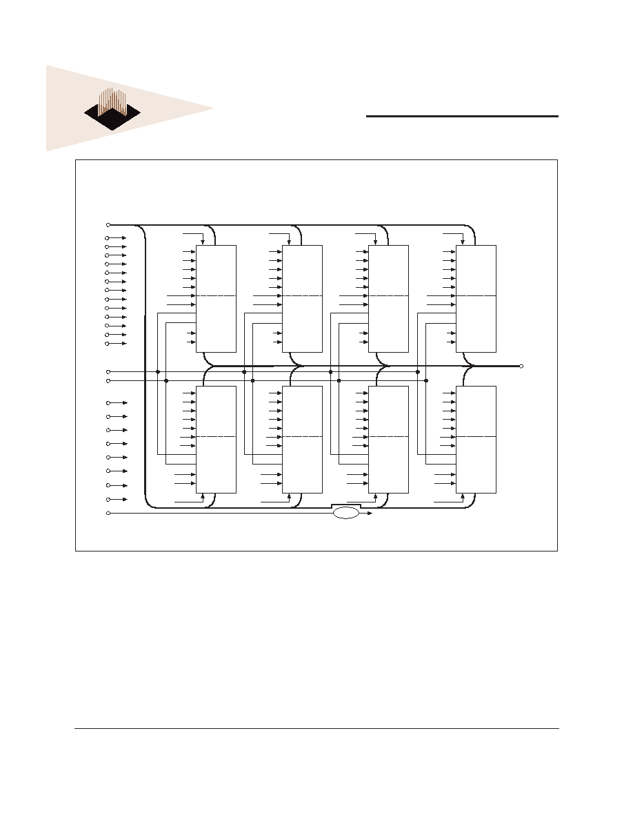
The WED2CG472512V is a Synchronous/Synchronous
Burst SRAM, 84 position Dual Key; Double High DIMM
(168 contacts) Module, organized as 4x512Kx72. The
Module contains sixteen (16) Synchronous Burst RAM
devices, packaged in the industry stan dard JEDEC
14mmx20mm TQFP placed on a Multilayer FR4 Substrate.
The Module Architecture is defi ned as a Sync/SyncBurst,
Flow-Through, with support for either linear or sequential
burst. This Module provides high performance, 2-1-1-1
accesses when used in Burst Mode, and when used in
Synchronous Only Mode, provides a high performance
cost advantage over BiCMOS asyn chro nous device
architectures.
Synchronous Only operations are performed via strapping
ADSC# Low, and ADSP#/ADV# High, which provides for
Ultra Fast Ac cess es in Read Mode while providing for
internally self-timed Early Writes.
Synchronous/Synchronous Burst operations are in
relation to an externally supplied clock, Registered
Address, Registered Global Write, Registered Enables as
well as an Asynchronous Output Enable. This Module has
been defi ned with full fl exibility, which allows individual
control of each of the eight bytes, as well as Quad Words
in both Read and Write Operations.
* This product is under development, is not qualifi ed or characterized and is subject to
change or cancellation without notice.
FEATURES
4x512Kx72 Synchronous, Synchronous Burst
Flow-Through
Architecture
Linear and Sequential Burst Support via MODE pin
Clock Controlled Registered Module Enable (EM#)
Clock Controlled Registered Bank Enables (E
1
#, E
2
#,
E
3
#, E
4
#)
Clock
Controlled
Byte
Write
Mode
Enable
(BWE#)
Clock
Controlled
Byte
Write
Enables
(BW
1
# - BW
8
#)
Clock
Controlled
Registered
Address
Clock Controlled Registered Global Write (GW#)
Asynchronous
Output
Enable
(G#)
Internally
Self-Timed
Write
Individual
Bank
Sleep
Mode
Enables
(ZZ
1
, ZZ
2
, ZZ
3
, ZZ
4
)
Gold Lead Finish
3.3V ± 10% Operation
Frequency(s): 100, 83, 67, 50MHz
Access Speed(s): t
KHQV
= 7.5, 9, 10, 12, 15ns
Common
Data
I/O
High Capacitance (30pF) Drive, at Rated Access Speed
Single
Total
Array
Clock
WED2CG472512V-D2
4
White Electronic Designs Corporation ∑ (602) 437-1520 ∑ www.whiteedc.com
White Electronic Designs
Aug. 2002
Rev. B
White Electronic Designs Corp. reserves the right to change products or specifi cations without notice.
ADVANCED
Operation E
1
# E
2
# E
3
# E
4
# ADSP#
ADSC# ADV# GW# G# CK
DQ Addr.
Used
Deselected Cycle, Power Down; Bank 1
H
X
*
*
X
L
X
X
X
L-H
High-Z
None
Deselected Cycle, Power Down; Bank 2
X
H
*
*
X
L
X
X
X
L-H
High-Z
None
Read Cycle, Begin Burst; Bank 1
L
H
*
*
L
X
X
X
L
L-H
Q
External
Read Cycle, Begin Burst; Bank 1
L
H
*
*
L
X
X
X
H
L-H
High-Z
External
Read Cycle, Begin Burst, Bank 2
H
L
*
*
L
X
X
X
L
L-H
Q
External
Read Cycle, Begin Burst; Bank 2
H
L
*
*
L
X
X
X
H
L-H
High-Z
External
Write Cycle, Begin Burst; Bank 1
L
H
*
*
H
L
X
L
X
L-H
D
External
Write Cycle, Begin Burst; Bank 2
H
L
*
*
H
L
X
L
X
L-H
D
External
Read Cycle, Begin Burst; Bank 1
L
H
*
*
H
L
X
H
L
L-H
Q
External
Read Cycle, Begin Burst; Bank 1
L
H
*
*
H
L
X
H
H
L-H
High-Z
External
Read Cycle, Begin Burst; Bank 2
H
L
*
*
H
L
X
H
L
L-H
Q
External
Read Cycle, Begin Burst; Bank 2
H
L
*
*
H
L
X
H
H
L-H
High-Z
External
Read Cycle, Continue Burst; Bank 1
X
H
*
*
X
H
L
H
L
L-H
Q
Next
Read Cycle, Continue Burst; Bank 1
X
H
*
*
X
H
L
H
H
L-H
High-Z
Next
Read Cycle, Continue Burst; Bank 2
H
X
*
*
X
H
L
H
L
L-H
Q
Next
Read Cycle, Continue Burst; Bank 2
H
X
*
*
X
H
L
H
H
L-H
High-Z
Next
Read Cycle, Continue Burst; Bank 1
H
H
*
*
X
H
L
H
L
L-H
Q
Next
Read Cycle, Continue Burst; Bank 1
H
H
*
*
X
H
L
H
H
L-H
High-Z
Next
Read Cycle, Continue Burst; Bank 2
H
H
*
*
X
H
L
H
L
L-H
Q
Next
Read Cycle, Continue Burst; Bank 2
H
H
*
*
X
H
L
H
H
L-H
High-Z
Next
Write Cycle, Continue Burst; Bank 1
X
H
*
*
H
H
L
L
X
L-H
D
Next
Write Cycle, Continue Burst; Bank 1
H
H
*
*
X
H
L
L
X
L-H
D
Next
Write Cycle, Continue Burst; Bank 2
H
X
*
*
H
H
L
L
X
L-H
D
Next
Write Cycle, Continue Burst; Bank 2
H
H
*
*
X
H
L
L
X
L-H
D
Next
Read Cycle, Suspend Burst; Bank 1
X
H
*
*
H
H
H
H
L
L-H
Q
Current
Read Cycle, Suspend Burst; Bank 1
X
H
*
*
H
H
H
H
H
L-H
High-Z
Current
Read Cycle, Suspend Burst; Bank 2
H
X
*
*
H
H
H
H
L
L-H
Q
Current
Read Cycle, Suspend Burst; Bank 2
H
X
*
*
H
H
H
H
H
L-H
High-Z
Current
Read Cycle, Suspend Burst; Bank 1
H
H
*
*
X
H
H
H
L
L-H
Q
Current
Read Cycle, Suspend Burst; Bank 1
H
H
*
*
X
H
H
H
H
L-H
High-Z
Current
Read Cycle, Suspend Burst; Bank 2
H
H
*
*
X
H
H
H
L
L-H
Q
Current
Read Cycle, Suspend Burst; Bank 2
H
H
*
*
X
H
H
H
H
L-H
High-Z
Current
Write Cycle, Suspend Burst; Bank 1
X
H
*
*
H
H
H
L
X
L-H
D
Current
Write Cycle, Suspend Burst; Bank 1
H
H
*
*
X
H
H
L
X
L-H
D
Current
Write Cycle, Suspend Burst; Bank 2
H
X
*
*
H
H
H
L
X
L-H
D
Current
Write Cycle, Suspend Burst; Bank 2
H
H
*
*
X
H
H
L
X
L-H
D
Current
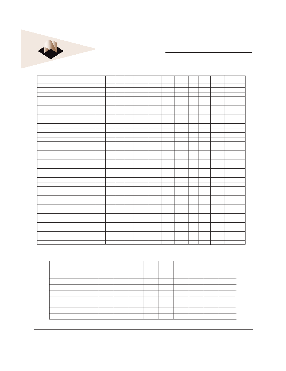
SYNC BURST ≠ TRUTH TABLE
Note A: All truth Table Functions Repeat for Bank 3 (E
3
#) and Bank 4 (E
4
#).
SYNCHRONOUS ONLY ≠ TRUTH TABLE
Operation
E
1
#
E
2
#
E
3
#
E
4
#
GW#
G#
ZZ
CK
DQ
Synchronous Write - Bank 1
L
H
H
H
L
H
L
High-Z
Synchronous Read - Bank 1
L
H
H
H
H
L
L
Synchronous Write - Bank 2
H
L
H
H
L
H
L
High-Z
Synchronous Read - Bank 2
H
L
H
H
H
L
L
Synchronous Write - Bank 3
H
H
L
H
L
H
L
High-Z
Synchronous Read - Bank 3
H
H
L
H
H
L
L
Synchronous Write - Bank 4
H
H
H
L
L
H
L
High-Z
Synchronous Read - Bank 4
H
H
H
L
H
L
L
Snooze Mode
X
X
X
X
X
X
H
X
High-Z

WED2CG472512V-D2
5
White Electronic Designs Corporation ∑ (602) 437-1520 ∑ www.whiteedc.com
White Electronic Designs
Aug. 2002
Rev. B
White Electronic Designs Corp. reserves the right to change products or specifi cations without notice.
ADVANCED
AC TEST CONDITIONS
RL = 50
VL = 1.25V
DQ Output
Z0 = 50
Z0 = 50
AC TEST LOAD
OUTPUT TEST EQUIVALENCIES
ABSOLUTE MAXIMUM RATINGS*
Voltage on V
cc
Relative to V
ss
-0.3V to +4.6V
V
IN
-0.3V to V
cc
+0.5V
Storage Temperature
-55∞C to + 125∞C
Operating Temperature (Commercial)
0∞C to +70∞C
Operating Temperature (Industrial)
-40∞C to +85∞C
Short Circuit Output Current
100mA
RECOMMENDED DC OPERATING CONDITIONS
Parameter
Sym
Min
Typ
Max
Units
Supply Voltage
V
cc
3.3
3.3
3.6
V
Supply Voltage
V
ss
0
0
0
V
Input High
V
IH
2.0
3.0
V
cc
+0.3
V
Input Low
V
IL
-0.3
0
0.3
V
Input Leakage
I
LI
-2
1
2
mA
Output Leakage
I
Lo
-2
1
2
mA
*Stress greater than those listed under "Absolute Maximum Ratings" may
cause permanent damage to the device. This is a stress rating only and
functional operation of the device at these or any other conditions greater
than those indicated in the operational sections of this specifi cation is not
implied. Exposure to absolute maximum rating conditions for extended
periods may affect reliability.
Input Pulse Levels
Vss to 3.0V
Input and Output Timing Ref.
1.25V
Output Test Equivalencies
See fi gure at left
DC ELECTRICAL CHARACTERISTICS READ CYCLE
Description
Sym
Typ
Max
Units
8.5
10
12
15
Power Supply Current
I
cc
1
2.0
2.9
2.7
2.7
2.5
A
Power Supply Current
Device Selected, No Operation
I
cc
875
1.8
1.8
1.3
1.3
A
Snooze Mode
I
cc
ZZ
270
350
350
350
350
mA
CMOS Standby
I
cc
3
500
700
700
700
700
mA
Clock Running-Deselect
I
cc
K
900
1.1
1.1
1.0
1.0
A