
KBP2005 thru KBP210
KBP
Glass Passivated Bridge Rectifiers
WEITRON
http://www.weitron.com.tw
KBP Outline Dimensions
Features:
Mechanical Data:
REVERSE VOLTAGE
50 to 1000 VOLTS
FORWARD CURRENT
2.0 AMPERES
1/3
20-Feb-06
Lead(Pb)-Free
P b
M
L
K
J
H
G
E
D
C
B
A
Dim
2.16
4.57
CHAMFER
o
3.18 X 45
0.71
1.52
3.56
12.70
15.24
11.68
10.67
14.22
Min
2.67
5.08
0.84
4.06
12.70
11.68
15.24
Max
KBP
All Dimensions in mm
M
L
G
E
A
K
J
H
B C
D
* Surge overload rating - 60 amperes peak
* Ideal for printed circuit board
* High case dielectric strength
* Reliable low cost construction utilizing molded plastic technique
* Plastic package used has Underwriters Laboratory
Flammability Classification 94V-0
* High temperature soldering guaranteed:
260∞C/10 seconds at 5lbs. (2.3kg) tension
* Case: Molded plastic body over passivated junctions
* Terminals: Plated lead solderable per MIL-STD-202, method 208
* Polarity: Polarity symbols marked on body
* Weight: 0.06 ounce, 1.7 grams

Maximum Rating
Characteristic
V
RRM
V
RMS
V
DC
I
AV
I
FSM
T
J
T
STG
50
35
50
100
70
100
200
140
200
400
280
400
2.0
60
-50 to +150
1.1
10.0
1000
-50 to +150
600
420
600
800
560
800
1000
700
1000
V
V
V
Uuits
A
A
Characteristic
Electrical Characteristic
Maximum Instantaneous Reverse Current
Maximum Forward Voltage Drop
per Bridge Element at 1.0A Peak
Rated DC Voltage, T
A
=25∞C
T
A
=100∞C
V
F
I
R
V
µA
Symbol
WEITRON
KBP2005 KBP201 KBP202 KBP204 KBP206 KBP208 KBP210
Symbol
KBP2005 KBP201 KBP202 KBP204 KBP206 KBP208 KBP210
Uuits
http://www.weitron.com.tw
2/3
Maximum repetitive peak reverse voltage
Maximum RMS voltage
Maximum DC blocking voltage
Maximum average forward rectified current
0.375" (9.5mm) lead length at T
A
=50∞C
Peak forward surge current 8.3mS
single half sine-wave super imposed on
rated load (MIL-STD-750D 4066 method)
Operating junction temperature range
Storage temperature range
∞C
∞C
KBP2005 thru KBP210
20-Feb-06
WEITRON
http://www.weitron.com.tw
KBP2005 thru KBP210
3/3
20-Feb-06
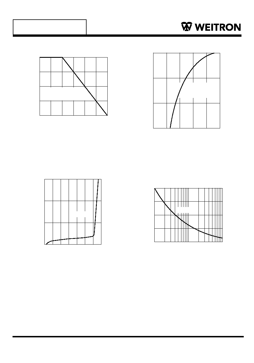
NUMBER OF CYCLES AT 60Hz
Fig.2 Maximum Non-repetitive Peak Forward
Surge Current Per Bridge Element
1 10 100
P
E
A
K
F
O
R
W
A
R
D
S
U
R
G
E
C
U
R
R
E
N
T(A)
60
45
30
15
0
Fig.4 Typical Instantaneous Forward
Per Bridge Element
INSTANTANEOUS FORWARD VOLTAGE (V)
0.4
0.6
0.8
1.0
1.2
1.4
T
J
= 25∞C
PULSE WIDTH = 300µs
1 % DUTY CYCLE
0.01
0.1
1.0
10
I
N
S
T
A
N
T
A
N
E
O
U
S
F
O
R
W
A
R
D
C
U
R
R
E
N
T(A)
PERCENT OF RATED PEAK REVERSE VOLTS (%)
Fig.3 Typical Reverse Characteristics
I
N
S
T
A
N
T
A
N
E
O
U
S
R
E
V
E
R
S
E
C
U
R
R
E
N
T(mA)
AMBIENT TEMPERATURE (∞C)
Fig.1 Typical Forward Current Derating Curve
0 25 50 75 100 125 150
A
V
E
R
A
G
E
F
O
R
W
A
R
D
C
U
R
R
E
N
T(A)
SINGLE PHASE HALF WAVE
60Hz RESISTIVE OR
INDUCTIVE LOAD
2.0
1.5
1.0
0.5
0
Ratings and Characteristics Curves
0
0.01
20
40
60
80
0.1
1.0
10
120
100
140
T
J
= 25∞C
T
J
= 25∞C