Surface Mount Switching Diode
*High Speed 4ns
*Low Rever Leakage Current
*Small Outline Surface Mount SOT-23 Package
Features:
MMBD4148
WEITRON
WEITRON
http://www.weitron.com.tw
SWITCHING DIODE
200mAMPERS
100VOLTS
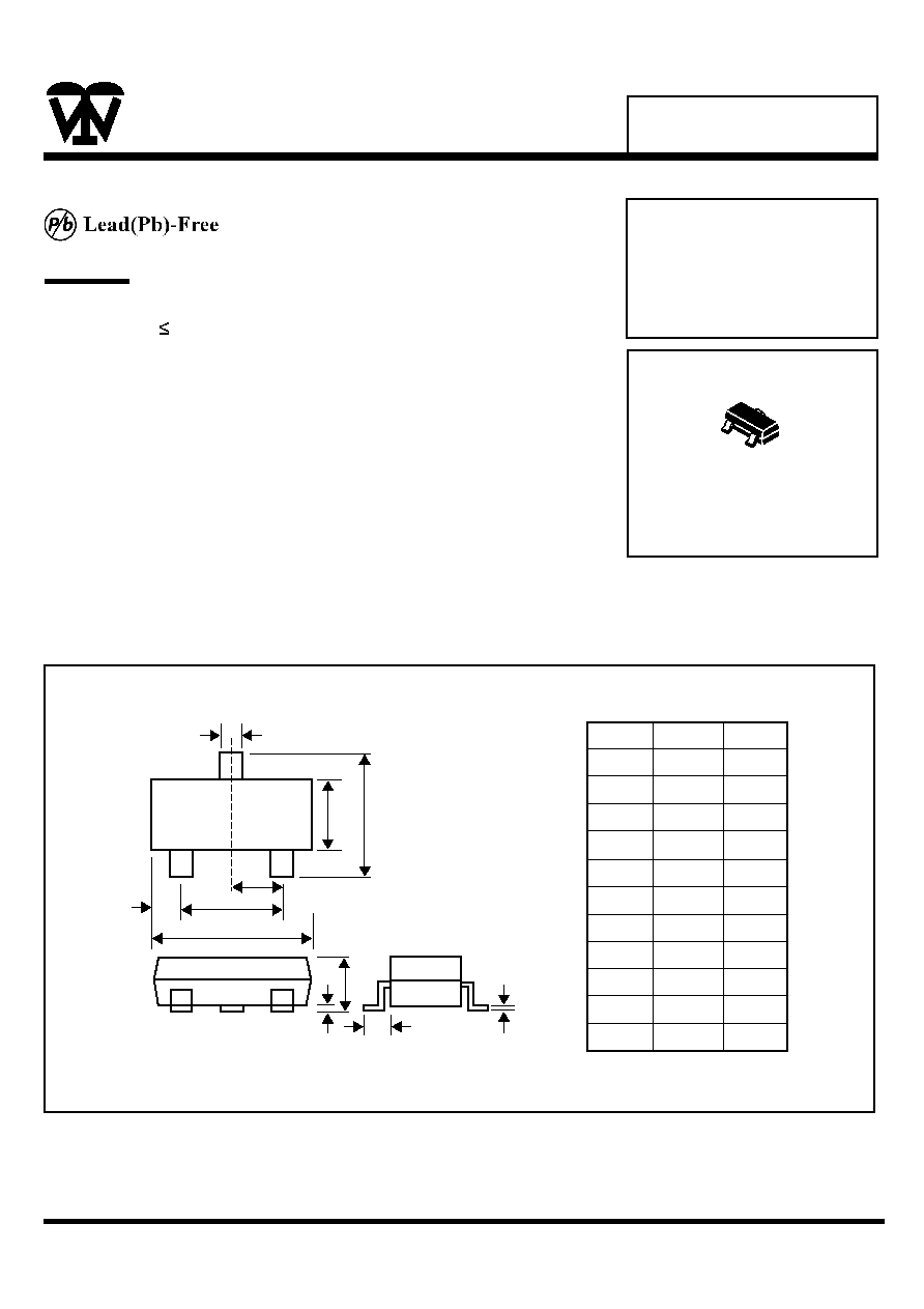
SOT-23 Outline Dimensions
SOT-23
Unit:mm
Dim
A
B
C
D
E
G
H
J
K
L
M
Min
0.35
1.19
2.10
0.85
0.46
1.70
2.70
0.01
0.89
0.30
0.076
Max
0.51
1.40
3.00
1.05
1.00
2.10
3.10
0.13
1.10
0.61
0.25
A
B
D
E
G
M
L
H
J
TOP VIEW
K
C
1
2
3
MMBD4148
WEITRON
WE IT R ON
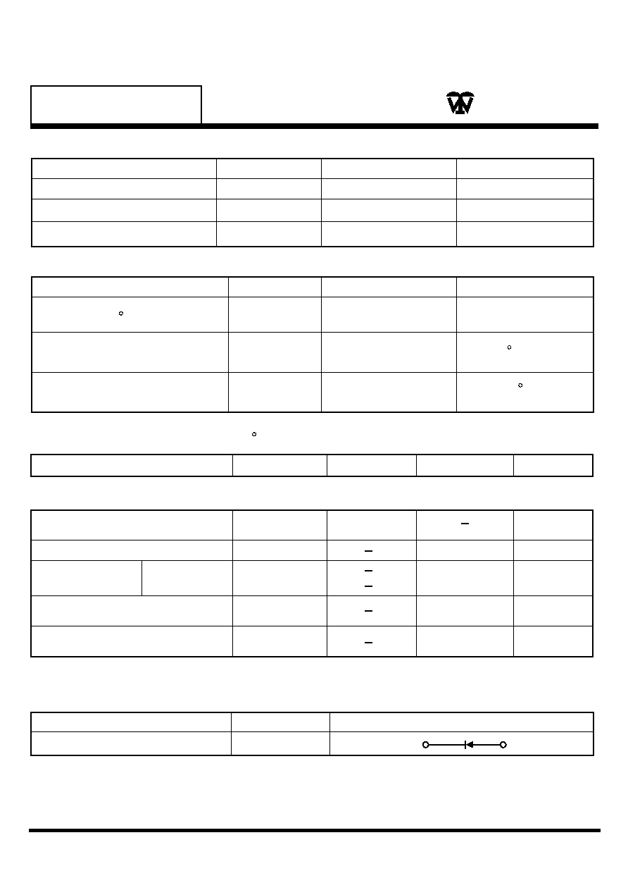
Maximum Ratings
Rating
Symbol
Value
Unit
Reverse Voltage
Forward Current
Peak Forward Surge Current
V
R
I
F
I
FM(Surge)
100
200
500
Vdc
mAdc
mAdc
Device Marking
Item
Marking
Eqivalent Circuitdiagram
MMBD4148
5D
1
3
Off Characteristics
Reverse Breakdown Votalge
(IR=100µAdc)
Forward Voltage(IF=10mAdc)
Reverse Voltage
Leakage Current
(V
R
=20Vdc)
(V
R
=75Vdc)
Revarse Recover Time
(I
F
=I
R
=10mAdc)
V(BR)
V
F
I
R
Diode Capacitance
(V
R
=0, f=1.0MHz)
C
T
trr
100
1000
0.025
5.0
4.0
4.0
Vcc
mVdc
µAdc
F
ns
1. FR-5=1.0x0.75x0.062 in 2.Alumina=0.4x0.3x0.024 in. 99.5% alumina.
Electrical Characteristics
(T
A
=25 C Unless Otherwise note)
Characterictics
Symbol
Max
Unit
Min
http://www.weitron.com.tw
T her mal C har acter istics
Characterictics
Symbol
Max
Unit
Total Device Dissipation FR-5
Board T
A
=25 C
Thermal Resistance, Junction
to Ambient
Junction and Storage
Temperature
P
D
R
JA
TJ, T
stg
556
-55 to + 150
mW
C/W
C
500
q
P

MMBD4148
VR, REVERSE VOLTAGE (VOLTS)
Figure 4. Capacitance
C
D
,
D
I
O
D
E
C
A
P
A
C
I
T
A
N
C
E
(
p
F)
0
2
4
6
8
0.68
0.64
0.60
0.56
0.52
WEITRON
WE IT R ON
http://www.weitron.com.tw
TA=85 C
TA= -40 C
TA=25 C
0.2
0.4
0.6
0.8
1.0
1.2
VF, FORWARD VOLTAGE (VOLTS)
Figure 2. Forward Voltage
IF
,
F
O
R
W
A
R
D
C
U
R
R
E
N
T
(
m
A
)
100
10
1.0
0.1
TA=125 C
TA=85 C
TA=55 C
TA=25 C
TA=150 C
0
10
20
30
40
50
VR, REVERSE VOLTAGE (VOLTS)
Figure 3. Leakage Current
IR
,
R
E
V
E
R
S
E
C
U
R
R
E
N
T
(
µ
A
)
0.001
0.01
0.1
1.0
10
+10V
820
2.0K
100 µH
0.1µF
50 OUTPUT
PULSE
GENERATOR
50 INPUT
SAMPLING
OSCILLOSCOPE
IF
D.U.T.
0.1µF
VR
INPUT SIGNAL
tr
tp
10%
90%
t
IF
IR
trr
t
IR(REC)=1.0mA
OUTPUT PULSE
(IF=IR=10mA, MEASURED
AT IR(REC)=1.0mA
Notes:1. A 2.0 k variable resistor for a Forward Current (IF) 0f 10 mA
2. Input pules is adjusted so IR(peak) is equal to 10 mA
3. tp trr
Figure 1. Recovery Time Equivalent Test Circuit
ª