
* Case : Molded plastic.
* Epoxy : UL 94V-0 rate flame retardant.
* Lead : Axial leads, solderable per MIL-STD-202, method 208 guranteed.
* Polarity : Color band denotes cathode end
* Mounting position : Any
* Weight : 1.65 grams
* Low forward voltage drop
* High current capability
* High reliability
* High surge current capability
6.0 Amp Silicon Rectifiers
Mechanical Data:
Features:
R-6 Outline Dimensions
25.4
-
8.6
9.1
1.2
1.3
8.6
9.1
P600A thru P600M
REVERSE VOLTAGE
50 TO 1000 VOLTS
FORWARD CURRENT
6.0 AMPERES
R-6
Lead(Pb)-Free
P b
http://www.weitron.com.tw
WEITRON
1/3
16-Dec-03
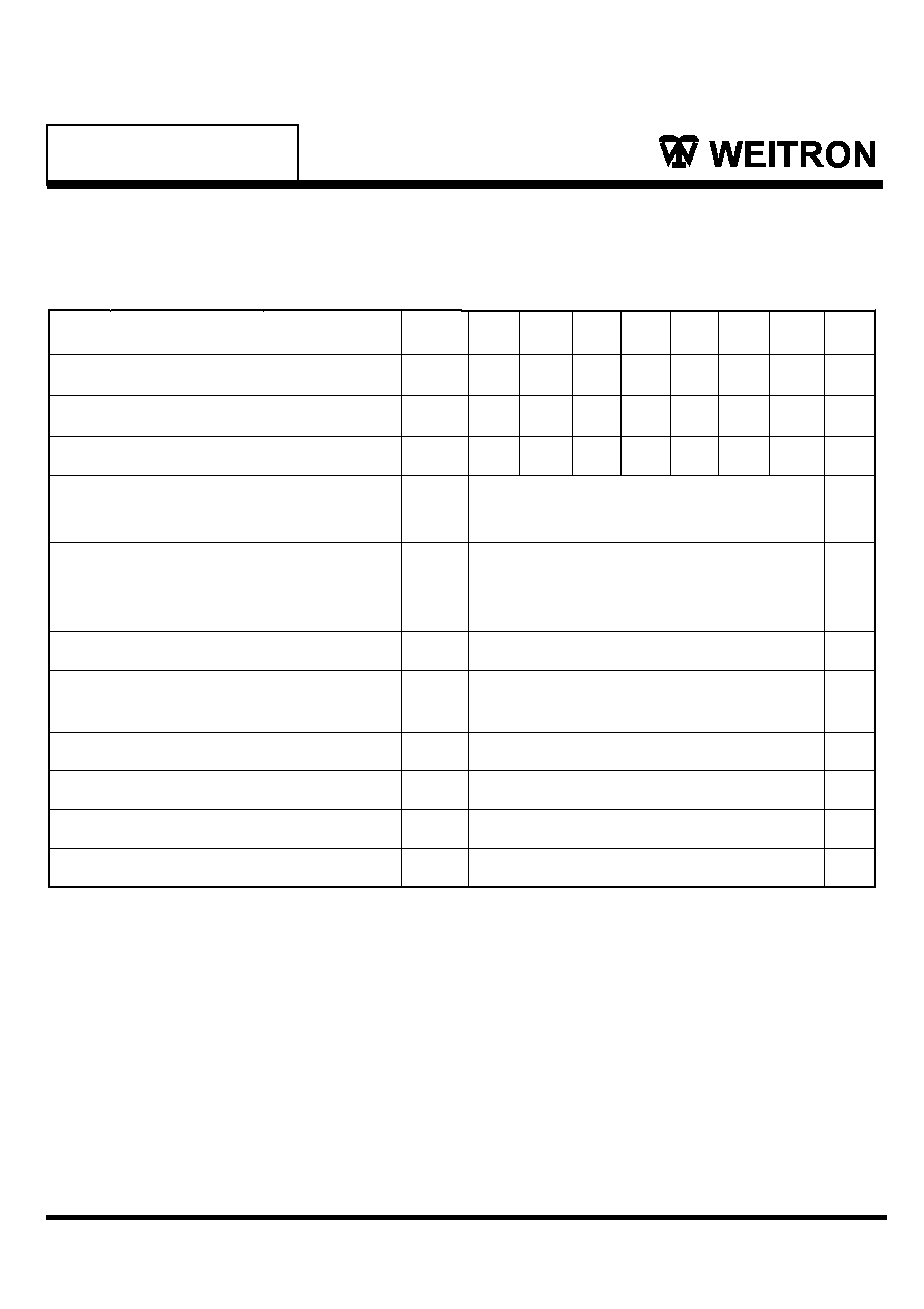
Maximum Ratings and Electrical Characteristics
Characteristics
Symbol
Unit
V
V
V
A
A
V
µA
∞C
∞C
Rating 25∞C Ambient Temperature Unless Otherwise Specified.
Single Phase Half Wave, 60Hz , Resistive or Inductive Load.
For Capacitive Load, Derate Current by 20%.
I
F(AV)
I
FSM
V
F
I
R
C
J
TJ
T
STG
-65 to +175
-65 to +175
∞C/W
1. Measured at 1.0MHz applied reverse voltage of 4.0V D.C.
2. Thermal Resistance from Junction to Ambient .375"(9.5mm) lead length.
10.0
400
100
10
pF
R
JA
NOTES:
800
560
800
50
35
50
100
70
100
200
140
200
400
280
400
600
420
600
1000
700
1000
6.0
400
0.95
P600A P600B P600D P600G P600J P600K P600M
P600A thru P600M
http://www.weitron.com.tw
WEITRON
2/3
16-Dec-03
Maximum Recurrent Peak Reverse Voltage
Maximum RMS Voltage
Maximum DC Blocking Voltage
Maximum Average Forward Rectified Current
.375"(9.5m) Lead length at T
A
=60∞C
Storage Temperature Range
Operating Temperature Range
Typical Thermal Resistance (Note 2)
Typical Junction Capacitance (Note 1)
Maximum DC Reverse Current @Tj=25∞C
At Rated DC Blocking Voltage @Tj=100∞C
Maximum Instantaneous at 6.0A DC
Peak Forward Surge Current,
8.3 ms Single Half Sine-Wave
Superimposed on Rated Load (JEDEC Method)
V
RRM
V
DC
V
RMS

P600A thru P600M
http://www.weitron.com.tw
WEITRON
3/3
16-Dec-03
0.1
1.0
10
100
RATING AND CHARACTERISTIC CURVES
FIG.3 - TYPICAL REVERSE CHARACTERISTICS
0 20 40 60 80 100 120 140
FIG.5 - TYPICAL THERMAL RESISTANCE VS. LEAD LENGTH
T
H
E
R
M
A
L
R
E
S
I
S
T
A
N
C
E
,
(
C
/
W
)
25
20
15
10
5
0
0 0.1 0.2 0.3 0.4 0.5 0.6 0.7 0.8 0.9 1.0
1
10
100
500
I
N
S
T
A
N
T
A
N
E
O
U
S
F
O
R
W
A
R
D
C
U
R
R
E
N
T
,
(
A
)
FORWARD VOLTAGE(V)
Pulse Width 300us
1% Duty Cycle
.6 .8 1.0 1.2 1.4 1.6 1.8 2.0
40
0.01
FIG.2-TYPICAL FORWARD CURRENT DERATING CURVE
A
V
E
R
A
G
E
F
O
R
W
A
R
D
C
U
R
R
E
N
T
,
(
A
)
6
5
4
3
2
1
Ground Plane
1" X 1" Copper
surface area
PC BOARD
Recommended
PC Board
Single Phase Half Wave 60Hz
Resistive Or Inductive Load
Standard PC Board
Mounting
Mounting
Tj=100∞C
EQUAL LEAD LENGTH TO HEAT SINK, INCHES
Tj=25∞C
Tj=25∞C
FIG.4-MAXIMUM NON-REPETITIVE FORWARD SURGE CURRENT
100
0
200
300
400
500
NUMBER OF CYCLES AT 60Hz
1
10
5
50
100
Tj=25∫C
8.3ms Single Half
Sine Wave
JEDEC method
FIG.1-TYPICAL FORWARD CHARACTERISTICS
0
0 20 40
60 80 100 120 140 160 180 200
AMBIENT TEMPERATURE,(∞C)
P
E
A
K
F
O
R
W
A
R
D
S
U
R
G
E
C
U
R
R
E
N
T
,
(
A
)
PERCENT OF RATED PEAK REVERSE VOLTAGE(%)
R
E
V
E
R
S
E
L
E
A
K
A
G
E
C
U
R
R
E
N
T
,
(
A
)
PC BOARD