ABSOLUTE MAXIMUM RATINGS
Collector-Emitter Voltage
Collector-Base Voltage
Emitter-Base Voltage
Collector Current (DC)
Symbol
VCEO
VCBO
VEBO
IC(DC)
Value
Unit
V
V
V
mA
Rating
Characteristics
Symbol
Min
Max
Unit
ELECTRICAL CHARACTERISTICS
Collector-Emitter Breakdown Voltage (IC= 1mA , IB=0)
Collector-Base Breakdown Voltage (IC=100µA , IE=0)
Emitter-Base Breakdown Voltage (IE = 10 µA , IC=0)
Collector-Base Cutoff Current (VCB = 30V)
Emitter-Base Cutoff Current (VEB = 10Vdc , I =0)
V(BR)CEO
V(BR)CBO
V(BR)EBO
ICBO
IEBO
10
-
-
-
-
-
100
V
V
V
nA
nA
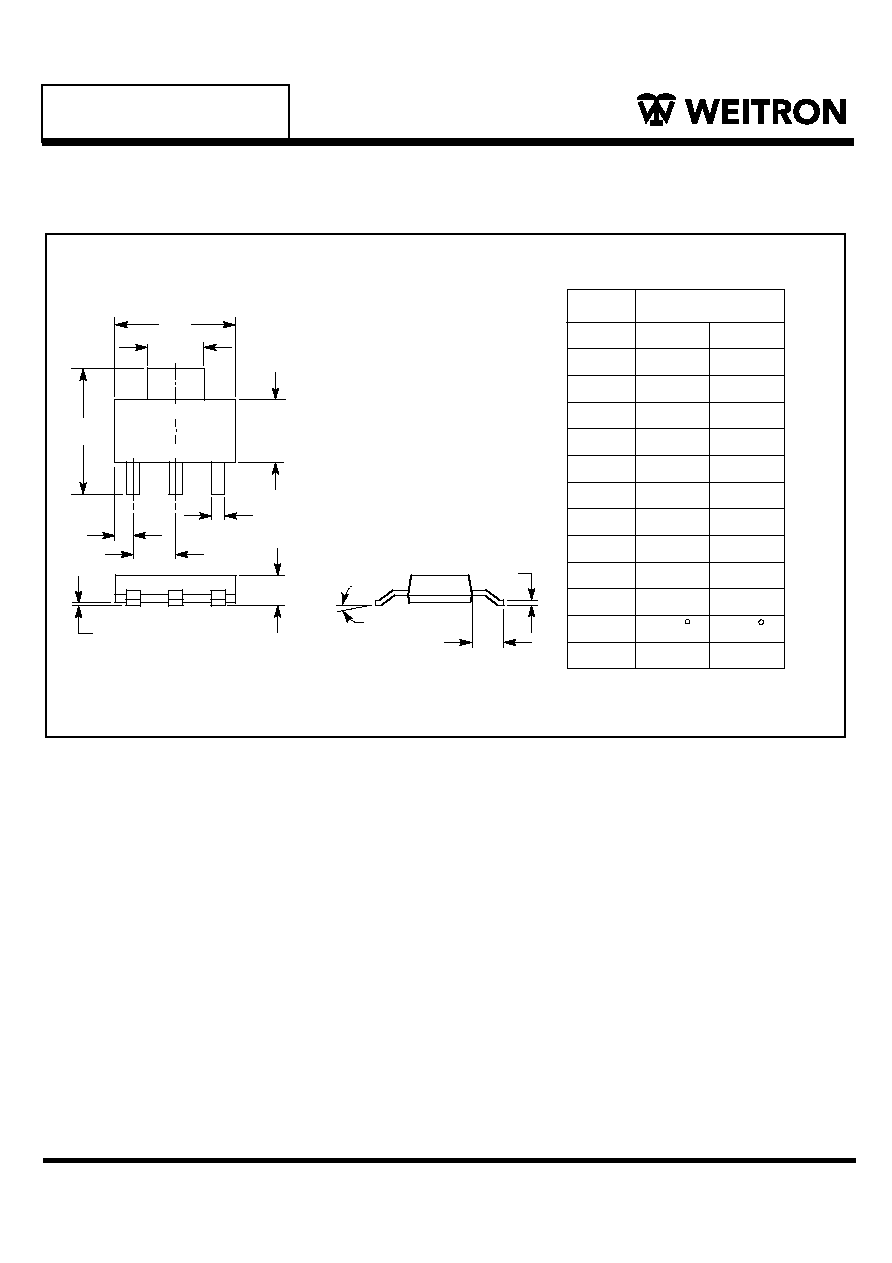
PZTA14
SOT-223
Tstg
PD
C
C
WEITRON
http://www.weitron.com.tw
Darlington NPN Silicon Planar Epitaxial Transistor
(Ta=25 C)
W
Junction Temperature
T j
150
Storage,Temperature
-55 to +150
Device Marking
PZTA14=A14
30
30
100
NOTE: 1.Device mounted on an epoxy printed circuit board 1.575 inches 1.575 inches 0.059 inches; mounting pad for the
3.EMITTER
2.COLLECTOR
1.BASE
C
Total Device Disspation T =25∞C
A
2
4.COLLECTOR
1
2
3
4
BASE
1
COLLECTOR
2, 4
3
EMITTER
30
30
10
300
collector lead min. 0.93 inches.
2
1/4
22-Sep-05
Lead(Pb)-Free
P b
PZTA14
ELECTRICAL CHARACTERISTICS Continued
(T
A
= 25 C unless otherwise noted)
Characteristic
Symbol
Min
Typ
Max
Unit
ON CHARACTERISTICS
DC Current Gain
(I
C
=10 mA, V
CE
= 5 V)
(I
C
= 100 mA, V
CE
= 5 V)
CE
= 5 V)
h
FE1
h
FE2
10K
20K
-
-
-
-
-
Collector-Emitter Saturation Voltage
(I
C
= 100 mA, I
B
= 0.1 mA)
V
CE(sat)
-
-
1.5
-
V
Base-Emitter Saturation Voltage
(I
C
= 100mA, V
V
BE( on)
-
2
V
DYNAMIC CHARACTERISTICS
Current-Gain-Bandwidth Product
(I
C
= 10 mA, V
CE
= 5V, f = 100 MHz)
f
T
125
-
MHz
-
-
WEITRON
http://www.weitron.com.tw
2/4
22-Sep-05

PZTA14
WEITRON
http://www.weitron.com.tw
3/4
22-Sep-05
0.1
V
CE
=5V
V
CE(sat)@
I
C
= 1000I
B
V
BE(on)@
V
CE
= 5V
V
CE =
5V
1
10
100
1000
Collector Current (mA)
hFE
Fig.1 Current Gain & Collector Current
Characieristics Curve
10000
100000
1000
1
10
100
0.1
Collector Current (mA)
Saturation V
oltage (V)
Fig.2 Saturation Voltage & Collector Current
1
1000
0.1
0.01
10
100
0.1
Collector Current (mA)
On V
oltage (mV)
Fig.3 On Voltage & Collector Current
1
10
1000
1
1
10
100
100
10
Collector Current (mA)
Cutoff Fr
equence (MHz)
Fig.4 Cutoff Frequency & Collector Current
1000
1000
Cob
0.1
10
100
Reverse-Biased Voltage (V)
Capacitance (pF)
Fig.5 Capacitance & Reverse-Biased Voltage
1
10
1
1
10
100
100
10
1000
1
Forward Biased Voltage (V)
Collector
Curr
ent (mA)
Fig.6 Safe Operating Area
10000
P
T =
1ms
P
T =
100ms
P
T =
1s