* For Surface Mount Application
* Glass Passivated Chip
* Low Reverse Leakage Current
* Low Forward Voltage Drop And High Current Capability
* Ultra Fast Switching For High Efficiency
* Plastic Meterial Has UL Flammability Classification 94V-0
* Case : Molded Plastic
* Terminals: Solder Plated Terminal-Solderable per MIL-STD-202, Method 208
* Polarity :Indicated by cathode band
* Weight : 0.002 Ounce ,0.064 grams
REVERSE VOLTAGE
50 TO 1000 VOLTS
FORWARD CURRENT
1.0 AMPERE
http://www.weitron.com.tw
US1A Thru US1M
Surface Mount Ultra Fast Rectifiers
Features:
WEITRON
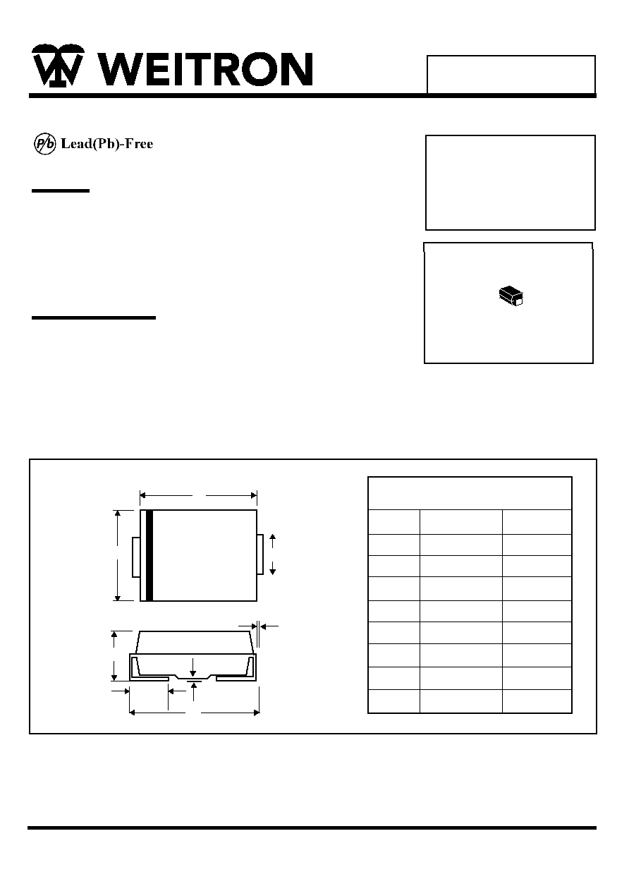
Mechanical Data
SMA(DO-214AC)
SMA Outline Dimension
Unit:mm
SMA
Dim
Min
Max
A
B
C
D
E
G
H
J
2.20
4.00
1.27
0.15
4.48
0.10
0.76
1.70
2.92
4.60
1.63
0.31
5.59
0.20
1.52
2.62
A
B
C
D
J
G
H
E

Maximum Ratings and Electrical Characteristics
Characteristics
Symbol
Unit
Maximum Recurrent Peak Reverse Voltage
Maximum RMS Voltage
Maximum DC Blocking Voltage
Maximum Average Forward
Rectified Current @T =75 C
Peak Forward Surge Current,
8.3 ms Single Half Sine-Wave
Superimposed on Rated Load (JEDEC Method)
Maximum Instantaneous At 1.0A DC
Maximum DC Reverse Current @T =25 C
At Rated DC Blocking Voltage @T =100 C
Maximun Reverse Recocery Time(Note1)
Typical Junction Capacitance (Note 2)
Typical Thermal Resistance (Note 3)
Operating Temperature Range
Storage Temperature Range
V
A
A
V
uA
C
C
Rating 25 C Ambient Temperature Unless Otherwise Specified.
Single Phase Half Wave, 60Hz , Resistive or Inductive Load.
For Capacitive Load, Derate Current by 20%.
VRRM
VRMS
VDC
IF(AV)
IFSM
VF
IR
C
J
T
TSTG
50
35
50
100
70
100
200
140
200
400
280
400
600
420
600
800
560
800
1000
700
1000
-55 to+150
-55 to+150
F
C/W
2.Measured at 1.0MHz applied reverse voltage of 4.0V DC.
3.Unit Mounted on PC board with 5.0 mm (0.03mm thick) land areas.
1.0
30
1.0
1.30
5.0
100
20
75
http://www.weitron.com.tw
WEITRON
J
J
US1A Thru US1M
US1A US1B US1D US1G
US1K
US1J
US1M
1.70
P
R
Trr
50
nS
NOTES:1.Reverse Recovery Test Conditions: F=0.5A, R=1.0A, =0.25A.
I
I
I
RR
T
A
A
T
100
10
2

WEITRON
US1A thru US1M
http://www.weitron.com.tw
t
rr
S et time bas e for 50/100 ns /cm
+0.5A
0A
-0.25A
-1.0A
F IG ..5 R evers e R ecovery Time C haracteris tic and Tes t C ircuit
50V DC
Approx
Os cillos cope
(Note 1)
P uls e
G enerator
(Note 2)
Device
Under
Tes t
(+)
(+)
(-)
(-)
0.01
0.1
1.0
10
100
1000
0
20
40
60
80
100
120
140
P E R C E NT OF R AT E D P E AK R E V E R S E V OLTAG E (%)
F IG ..4 T ypical R evers e C haracteris tics
T = 100∞C
j
T = 25∞C
j
0.01
0.1
1.0
10
0
0.4
0.8
I
,
I
N
S
T
A
N
T
A
N
E
O
U
S
F
O
R
W
A
R
D
C
U
R
R
E
N
T
(
A
)
F
V , INS TANTANE OUS F OR WAR D V OLTAG E (V )
F
F IG .2 Tpical F orward C haracteris tics
1.2
1.6
2.0
US 1A - US 1D
US 1G
US 1J - US 1M
0
10
20
30
40
1
10
100
I
,
P
E
A
K
F
O
R
W
A
R
D
S
U
R
G
E
C
U
R
R
E
N
T
(
A
)
F
S
M
NUMB E R OF C Y C LE S AT 60Hz
F IG . 3 F orward S urge C urrent Derating C urve
S ingle Half S ine-Wave
(J E DE C Method)
T = 150∞C
j
0
0.5
1.0
25
50
75
100
125
150
I
,
A
V
E
R
A
G
E
R
E
C
T
I
F
I
E
D
C
U
R
R
E
N
T
(
A
)
(
A
V
)
T , T E R MINAL T E MP E R AT UR E (∞C )
T
F IG .1 F orward C urrent Deratin C urve