TRANSIENT
VOLTAGE
SUPPRESSORS
300 WATTS
3-36 VOLTS
* Transient Protection for data lines as per IEC 61000-4-2(ESD)15KV(air),
8KV(contact)
* 300 Watts Peak Power Protection. (tp=8/20µS)
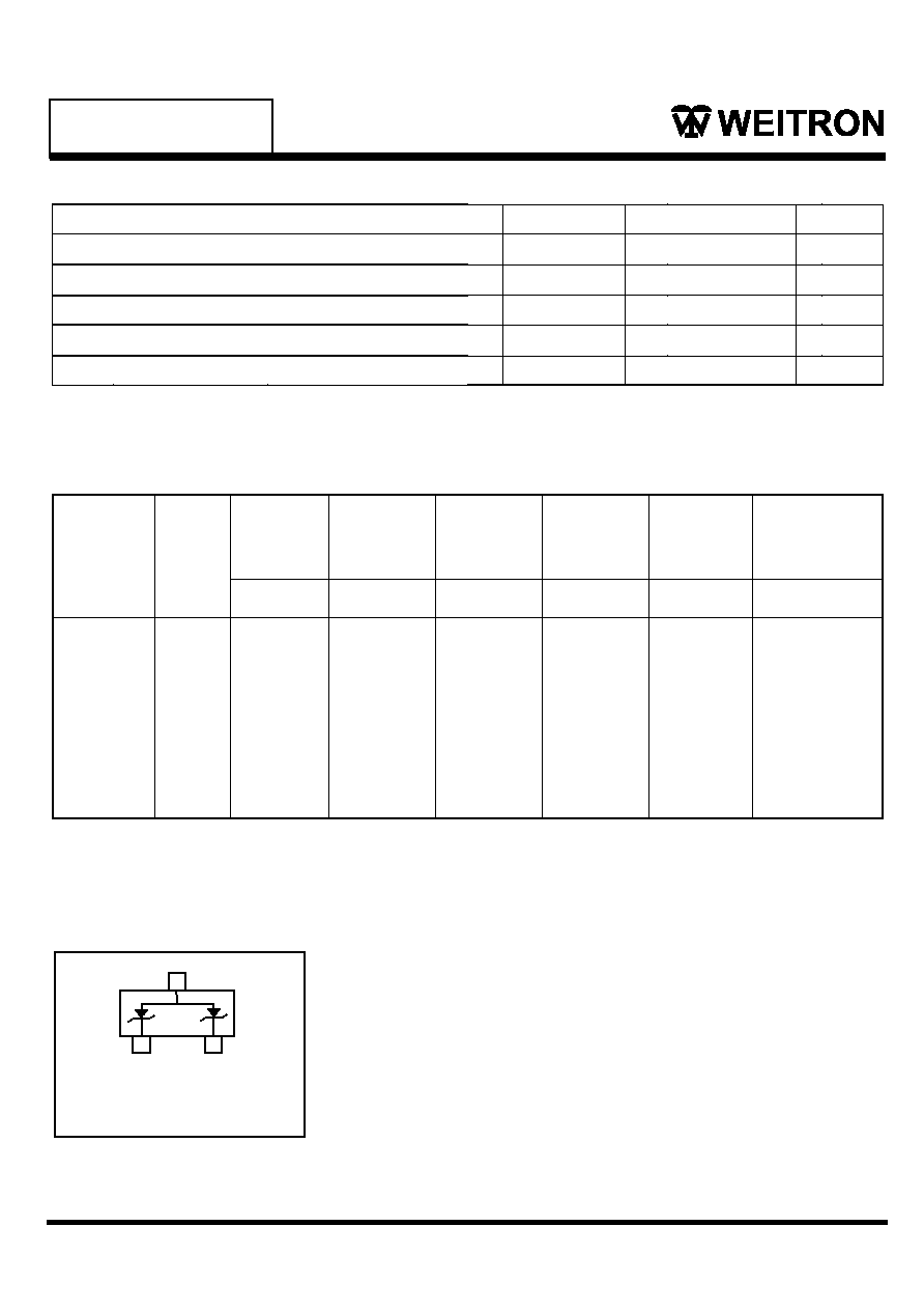
* Protects Two Unidirectional Lines with pin3 used as a common anode
Connection or One Bidirectional Line between pin1 & pin2
* Low Leakage Current
* Excellent Clamping Capability
* Transient Voltage Suppressors Encapsulated in a SC-59 Package
* Case : Molded Epoxy
* Marking : Marking Code
* Weight : 0.008 grams(approx)
Features:
Mechanical Data:
Surface Mount TVS Diode Array
for ESD Protection
Lead(Pb)-Free
P b
1
2
3
SC-59
J
K
G
D
C
H
S
A
L
B
3
2
1
Top View
A
B
C
D
G
H
J
K
L
S
2.70
1.30
1.00
0.35
1.70
0.00
0.10
0.20
1.25
2.25
3.10
1.70
1.30
0.50
2.30
0.10
0.26
0.60
1.65
3.00
Dim Min
Max
All Dimension in mm
SC-59
SC-59 Outline Dimension
WOST03C thru
WOST36C
WEITRON
http://www.weitron.com.tw
1/3
Rev.A 19-Dec-05

Electrical Characteristics(T
A
=25∞C Unless Otherwise Noted)
Part
Number
Marking
Code
Reverse
Stand off
Voltage
Breakdown
Voltage
VBR@1mA
Max
Clamping
Voltage
Max
Clamping
Voltage
Max
Reverse
Leakage
R
@1A
@5A
@VRWM
Capacitance
@V,IMHZ
VRWM(V)
MIN(V)
Vc(V)
Vc(V)
(uA)
(PF)
WOST03C
M03
3.3
4-5
7.0
8.5
100
700
WOST05C
M05
5.0
6.1-7.4
9.8
11
12
420
WOST36C
M36
36.0
40.0-47.0
60.0
75
0.5
60
WOST12C
M12
12.0
13.3-16.3
19.0
24
0.5
150
WOST15C
M15
15.0
16.7-20.4
24.0
30
0.5
100
WOST24C
M24
24.0
26.7-32.6
43.0
55
0.5
60
NOTE:1. Suffix"C" denotes Bi-directional device.
I
Bidirectional
Configuration
Eqivalent Circuit Diagram:
WOST03C thru
WOST36C
Maximum Ratings(T
A
=25∞C Unless Otherwise Noted)
Characteristic
Symbol
Votle
Unit
P
PK
R
JA
300
556
260(10s)
W
∞C/W
Operating Temperature Range
Lead Soldering Temperature
Thermal Resistance, Junction to Ambient
Peak Pulse Power Dissipation (t
P
= 8/20s)
T
J
T
L
-55 to +125
∞C
T
stg
-55 to +150
∞C
∞C
Storage Temperature Range
PIN 1-3 or PIN 2-3
WEITRON
http://www.weitron.com.tw
2/3
Rev.A 19-Dec-05

WOST03C thru
WOST36C
10
1
0.1
0.01
0.1 1 10 100 1000
0 25 50 75 100 125 150
0
10
20
30
40
50
60
70
80
90
100
110
0
10
20
30
40
50
60
70
80
90
100
110
Pulse Duration - tp (us)
P
P
k
a
e
u
P
e
s
o
P
-
r
e
w
K
P
W
k
(
)
FIG.1 Non-Repetitive Peak Pulse Power vs. Pulse Time
Ambient Temperature - T
A
(
o
C)
%
f
o
I
r
o
r
e
w
o
P
d
e
t
a
R
P
P
FIG.2 Power Derating Curve
0
5
10
15
20
25
30
Time (us)
I
f
o
t
n
e
c
r
e
P
P
P
e
-t
td=I
PP
/2
Wave form
Paramete rs:
tr = 8 µs
td = 20 µs
FIG.3 Pulse Waveform
WEITRON
http://www.weitron.com.tw
3/3
Rev.A 19-Dec-05


