
Surface Mount Schottky Barrier Diodes
*Extremely Fast Switching Speed
*Low Forward Voltage
*Very Small Conduction Losses
*Schottky Barrier Diodes Encapsulated in a SOT-323 Package
Description:
These schottky barrier diodes are designed for high speed
switching applications circuit protection, and voltage clamping,
Extremely low forward voltage reduces conduction loss,
Miniature surface mount package is excellent for hand held and
portable applications where space is limited.
Features:
WEITRON
WSD715F/WSD717F
SMALL SIGNAL
SCHOTTKY DIODES
30m AMPERES
40-45 VOLTS
hpp://www.weitron.com.tw
SOT-323(SC-70)
Unit:mm
SOT-323 Outline Demensions
1
2
3
A
B
D
E
G
M
L
H
J
T OP VIE W
K
C
Dim
A
B
C
D
E
G
H
J
K
L
M
Min
0.30
1.15
2.00
-
0.30
1.20
1.80
0.00
0.80
0.42
0.10
Max
0.40
1.35
2.40
0.65
0.40
1.40
2.20
0.10
1.00
0.53
0.25
SOT-323
WSD706F
WEITRON
WEITRON
WEITRON
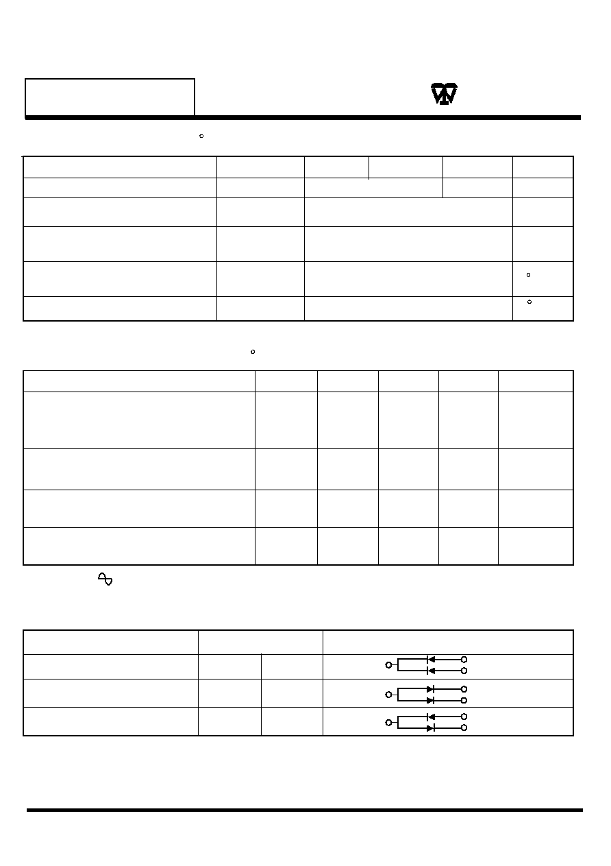
Maximum Ratings
(TA=25 C Unless otherwise noted)
Characteristic
Reverse Voltage
Average Rectifier
Forward Current
Operating Junction
Temperature Range
Storage Temperature Range
Symbol
VR
IF(AV)
IFSM
TJ
Tstg
Unit
30
-55 to +125
-55 to +125
Volts
mA
mA
C
C
Device Marking
Item
Marking
Eqivalent Circuit diagram
1
2
3
1
2
3
WSD715F
WSD717F
WSD706
JD
JE
JF
1
2
3
Electrical Characteristics
(TA=25 C Unless otherwise noted)
Characteristic
Symbol
Reverse Breakdown Voltage (IR=10�A)
Forward Voltage
IF=1.0mA
Total Capacitance
(VR=1.0V, f=1.0MHz)
Reverse Leakage
VR=10V
V(BR)R
VF
CT
IR
Min
Typ
Max
Unit
40
0.37
2.0
-
1.0
Volts
Volts
PF
�Adc
http://www.weitron.com.tw
Peak Surge
Forward Current(1)
200
WSD715F/WSD717F
WSD706F
WSD715
WSD717F
WSD706F
40
45
WSD715F/WSD717F
WSD706F
45
60HE for 1
1.
3D
3E
3J

0
5
1
0
1 5
2
0
2 5
3 0
3
5
100n
10n
1n
pulse measurement
Typ.
100
10
1
R
E
V
E
R
S
E
C
U
R
R
E
N
T
:
I
R
(
A
)
REVERSE VOLTAGE : V
R
(V)
FIG3. Reverse characteristics
Ta 75 C
Ta 25 C
Ta 125 C
Ta
25 C
=
=
=
= -
0
2
4
6
8
10
12
14
1
2
5
10
20
50
100
f 1MHz
Ta 25 C
REVERSE VOLTAGE : V
R
(V)
C
A
P
A
C
I
T
A
N
C
E
B
E
T
W
E
E
N
T
E
R
M
I
N
A
L
S
:
C
T
(
p
F
)
FIG4. Capacitance between
terminals characteristics
=
=
0
0.2
0.4
0.6
0.8
1.0
1.2
1.4
1m
10m
100m
pulse measurement
1
10
100
1000m
Typ.
F
O
R
W
A
R
D
C
U
R
R
E
N
T
:
I
F
(
A
)
FORWARD VOLTAGE : V
F
(V)
FIG2. Forward characteristics
Ta 75 C
Ta 25 C
Ta
25 C
Ta
125
C
=
=
=
= -
0
0
20
40
60
80
100
25
50
75
100
125
I
o
C
U
R
R
E
N
T
(
%
)
AMBIENT TEMPERATURE : Ta(
C )
FIG1. Derating curve
(mounting on glass epoxy PCBs)
Electrical characteristic curves(Ta=25 C)
WEITRON
http://www.weitron.com.tw
WSD715F/WSD717F
WSD706F