 | –≠–ª–µ–∫—Ç—Ä–æ–Ω–Ω—ã–π –∫–æ–º–ø–æ–Ω–µ–Ω—Ç: WSD751S | –°–∫–∞—á–∞—Ç—å:  PDF PDF  ZIP ZIP |

http://www.weitron.com.tw
WEITRON
WSD751S
SMALL SIGNAL
SCHOTTKY DIODES
30m AMPERES
40 VOLTS
*Extrmely High Switching Speed.
*Low Forward Voltage and Low Reverse Current.
*High Reliability.
*Schottky Barrier Diodes Encapsulated in a SOD-523 Package
Description:
Feature:
These schottky barrier diodes are designed for high speed
switching applications circuit protection, and voltage clamping,
Extremely low forward voltage reduces conduction loss,
Miniature surface mount package is excellent for hand held and
portable applications where space is limited.
Surface Mount Schottky Barrier Diodes
Dim
A
B
C
D
E
J
K
Min
1.10
0.70
0.50
0.25
0.15
0.07
1.50
Max
1.30
0.90
0.70
0.35
0.25
0.20
1.70
S OD-523
P IN 1. C A T HODE
2. A NODE
SOD-523 Outline Dimensions
SOD-523
1
2
Lead(Pb)-Free
P b
WEITRON
WSD751S
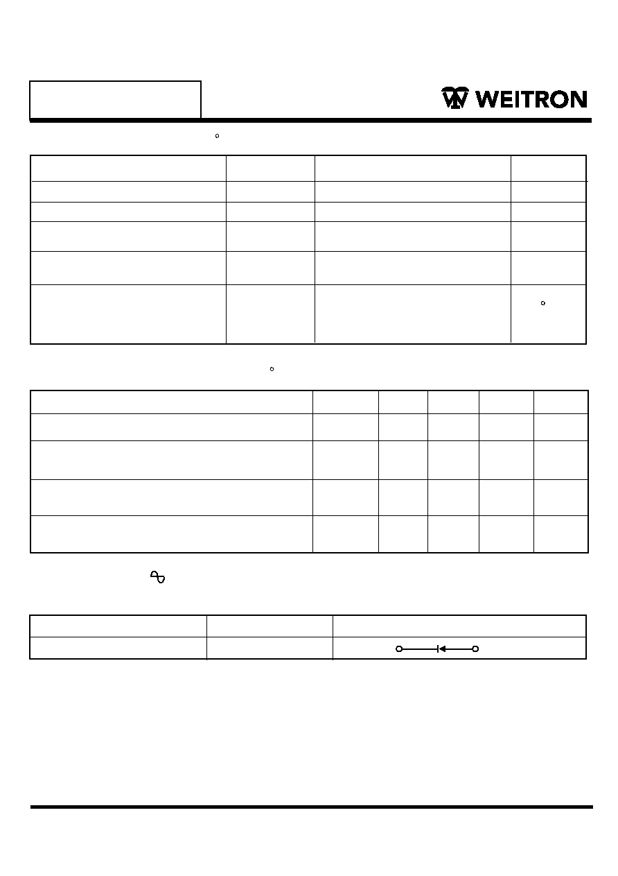
Maximum Ratings
(Ta=25 C Unless otherwise noted)
Characteristic
DC Reverse Voltage
Average Rectifier
Forward Current
Peak Forward Surge Current
Operating Junction
Temperature Range
Storage Temperature Range
Symbol
VR
VR=1V, f=MHZ
VRM
IF(AV)
IFSM
TJ
Tstg
Value
Unit
30
30
200
-40 to +125
Volts
Volts
mA
mA
C
Device Marking
Item
Marking
Eqivalent Circuit diagram
2
1
Electrical Characteristics
(TA=25 C Unless otherwise noted)
http://www.weitron.com.tw
(1)
Characteristic
Symbol
Reverse Breakdown Voltage (IR=100µA)
Forward Voltage
IF=1.0mA
Reverse Leakage
V(BR)R
VF
IR
Min
Max
Unit
30
Volts
Volts
µAdc
0.37
0.5
WSD751S
5
NOTE:
1. 60HZ for 1
Peak Reverse Voltage
40
TYP
Capacitance Between Terminals
C T
2.0
PF
VR=30V

Electrical characteristic curves (Ta = 25∞C unless specified otherwise)
0
Ta
=
1
25
˚C
T a = 75˚C
T a = 25˚C
T a = -25˚C
0.2
0.4
0.6
0.8
1.0
1.2
1.4
1m
10m
100m
puls e meas urement
1
10
100
1000m
T yp.
F
O
R
W
A
R
D
C
U
R
R
E
N
T
:
I
F
(
A
)
F O R W AR D V O LT AG E : V
F
(V )
F ig. 1 F orward characteris tics
0
5
10
15
20
25
30
35
100n
10n
1n
T a = 125˚C
T a = 75˚C
T a = 25˚C
T a = -25˚C
puls e meas urement
T yp.
100
10
1
R E V E R S E V OLT AG E : V
R
(V )
R
E
V
E
R
S
E
C
U
R
R
E
N
T
:
I
R
(
A
)
F ig. 2 R evers e characteris tics
0
2
4
6
8
10
12
14
1
2
5
10
20
50
100
f = 1MHz
T a = 25˚C
R E V E R S E V OLT AG E : V
R
(V )
C
A
P
A
C
I
T
A
N
C
E
B
E
T
W
E
E
N
T
E
R
M
I
N
A
L
S
:
C
T
(
p
F
)
F ig. 3 C apacitance between
terminals characteris tics
WSD751S
WEITRON
http://www.weitron.com.tw