 | –≠–ª–µ–∫—Ç—Ä–æ–Ω–Ω—ã–π –∫–æ–º–ø–æ–Ω–µ–Ω—Ç: W566B151 | –°–∫–∞—á–∞—Ç—å:  PDF PDF  ZIP ZIP |

W566BXXX
3S/3HQ SPEECH+MELODY PROCESSOR
(BandDirector
TM
Series)
Publication Release Date: April 24, 2002
- 1 - Revision A1
1. GENERAL DESCRIPTION
The W566Bxxx is a powerful embedded microcontroller (
µ
C) dedicated for speech and melody
synthesis application. This series IC is tailored for plush toy, educational toy or music instrument. With
the help of 16 bits microprocessor (
µ
P) W566-16, the W566Bxxx can synthesize multi-channel speech
and melody. 3-track of synthesized speech can be in different kinds of format, for example ADPCM
and MDPCM. Regarding synthesized melody, W566Bxxx can provide 2-track of Tone melody (T-
melody) plus 2-track percussion sound (2T+2Per), or 3-track of
High-Quality melody (HQ-melody)
that
can emulate the characteristics of musical instruments. These signals can be mixed flexibly through 4-
input Mixer to produce colorful effect. The result of Mixer is converted to analog signal to drive speaker
output.
W566Bxxx has two kinds of power saving modes: one is HOLD mode and the other is STOP mode. In
HOLD mode, the specific peripherals can be inactivated and IC can operate at the sub-clock.
Consequently, the W566Bxxx can perform some special tasks periodically. In STOP mode, all the IC's
peripherals are disable which is designated specially for try-me application. Besides, W566Bxxx can
sink 8mA at most for high-current application.
Following table depicts the W566Bxxx series.
PART#
W566B025 W566B030
W566B040
W566B060
W566B080
W566B100
W566B120
ROM (Byte)
94K
108K
126K
200K
254K
328K
382K
RAM (Byte)
256
256
256
256
256
256
256
Operating
Speed
8/4 MHz
8/4 MHz
8/4 MHz
8/4 MHz
8/4 MHz
4 MHz
4 MHz
Duration1
(sec)
1
25"
30"
36"
61"
80"
105"
124"
Duration2
(sec)
2
19"
23"
27"
46"
60"
79"
93"
In : Bid
3
4 : 16
4 : 16
4 : 16
4 : 16
4 : 16
0 : 16
0 : 16
Speaker
DAC
DAC
DAC
DAC
DAC
DAC
DAC
Mixer Inputs
4
4
4
4
4
4
4
Speech Tracks
4
3
3
3
3
3
3
3
Speech
Algorithms
ADPCM
MDPCM
PCM
ADPCM
MDPCM
PCM
ADPCM
MDPCM
PCM
ADPCM
MDPCM
PCM
ADPCM
MDPCM
PCM
ADPCM
MDPCM
PCM
ADPCM
MDPCM
PCM
Melody Tracks
3
3
3
3
3
3
3
Instrument
Types
HQ
Tone
Voice
HQ
Tone
Voice
HQ
Tone
Voice
HQ
Tone
Voice
HQ
Tone
Voice
HQ
Tone
Voice
HQ
Tone
Voice
IR-Carrier
¸
¸
¸
¸
¸
¸
¸
Number of
System Clocks
2
2
2
2
2
2
2
Power
Management
HOLD
STOP
HOLD
STOP
HOLD
STOP
HOLD
STOP
HOLD
STOP
HOLD
STOP
HOLD
STOP

W566BXXX
- 2 -
Following table depicts the W566Bxxx series, continued.
PART#
W566B150
W566B170
W566B210
W566B260
W566B300
W566B340
ROM (Byte)
460K
510K
640K
766K
912K
1022K
RAM (Byte)
256
256
256
256
256
256
Operating Speed
4 MHz
4 MHz
8/4 MHz
8/4 MHz
8/4 MHz
8/4 MHz
Duration1
(sec)
1
150"
167"
212"
255"
304"
342"
Duration2
(sec)
2
113"
125"
159"
191"
228"
257"
In : Bid
3
0 : 16
0 : 16
4 : 16
4 : 16
4 : 16
4 : 16
Speaker Driver
DAC
DAC
DAC
DAC
DAC
DAC
Mixer Inputs
4
4
4
4
4
4
Speech Tracks
4
3
3
3
3
3
3
Speech Algorithms
ADPCM
MDPCM
PCM
ADPCM
MDPCM
PCM
ADPCM
MDPCM
PCM
ADPCM
MDPCM
PCM
ADPCM
MDPCM
PCM
ADPCM
MDPCM
PCM
Melody Tracks
3
3
3
3
3
3
Instrument Types
HQ
Tone
Voice
HQ
Tone
Voice
HQ
Tone
Voice
HQ
Tone
Voice
HQ
Tone
Voice
HQ
Tone
Voice
IR-Carrier
¸
¸
¸
¸
¸
¸
Numbers of System
Clock
2
2
2
2
2
2
Power Management
HOLD
STOP
HOLD
STOP
HOLD
STOP
HOLD
STOP
HOLD
STOP
HOLD
STOP
Notes:
1. The Duration1 is calculated based on 6000Hz*4-bits = 24 Kbps, 24 Kbps on the assumption that all the ROM space is used
to store speech data.
2. The Duration2 is calculated based on 8000Hz*4-bits = 32 Kbps, 32 Kbps on the assumption that all the ROM space is used
to store speech data.
3. "In" is the number of input pins; "Bid" is the number of I/O pins.
4. Synthesized speech in ADPCM/MDPCM format.

W566BXXX
Publication Release Date: April 24, 2002
- 3 - Revision A1
Following table depicts the W566Bxxx series, continued.
PART#
W566B101
W566B121
W566B151
W566B171
ROM (Byte)
328K
382K
460K
510K
RAM (Byte)
256
256
256
256
Operating Speed
8/4 MHz
8/4 MHz
8/4 MHz
8/4 MHz
Duration1
(sec)
1
105"
124"
150"
167"
Duration2
(sec)
2
79"
93"
113"
125"
In : Bid
3
4 : 16
4 : 16
4 : 16
4 : 16
Speaker Driver
DAC
DAC
DAC
DAC
Mixer Inputs
4
4
4
4
Speech Tracks
4
3
3
3
3
Speech Algorithms
ADPCM
MDPCM
PCM
ADPCM
MDPCM
PCM
ADPCM
MDPCM
PCM
ADPCM
MDPCM
PCM
Melody Tracks
3
3
3
3
Instrument Types
HQ
Tone
Voice
HQ
Tone
Voice
HQ
Tone
Voice
HQ
Tone
Voice
IR-Carrier
¸
¸
¸
¸
Numbers of System Clock
2
2
2
2
Power Management
HOLD
STOP
HOLD
STOP
HOLD
STOP
HOLD
STOP
Notes:
1. The Duration1 is calculated based on 6000Hz*4-bits = 24 Kbps, 24 Kbps on the assumption that all the ROM space is used
to store speech data.
2. The Duration2 is calculated based on 8000Hz*4-bits = 32 Kbps, 32 Kbps on the assumption that all the ROM space is used
to store speech data.
3. "In" is the number of input pins; "Bid" is the number of I/O pins.
4. Synthesized speech in ADPCM/MDPCM format.

W566BXXX
- 4 -
2. FEATURES
∑
Wide operating voltage:
-
4MHz @ 2.4 volt to 5.5 volt
-
8MHz @ 3.6 volt to 5.5 volt
∑
Sophisticated power managements:
-
Dual system clocks, one is 8 MHz and the other is 32768 Hz
-
HOLD mode for dealing with interrupt events only
-
STOP mode for stopping all IC operation
∑
4 input pins
∑
16 I/O pins and 8 of them can sink 8 mA in their output portion
∑
10-bit Current type digital-to-analog converters (DAC) to drive speaker output
∑
Multiple synthesized speech formats: ADPCM/MDPCM/PCM
∑
3 tracks synthesized ADPCM/MDPCM speech at programmable playback rate
∑
2 tracks Tone melody which can emulate envelope of music instruments
∑
3 tracks High-Quality melody that can emulate characteristic of musical instruments
∑
4-input/10-bit-resolution Mixer can mix the speech and melody signals flexibly
∑
Built-in IR carrier generation circuit for simplification firmware IR application
∑
Built-in 4 timers for speech/melody synthesis and general purpose application
∑
Available package: COB
W566BXXX
Publication Release Date: April 24, 2002
- 5 - Revision A1
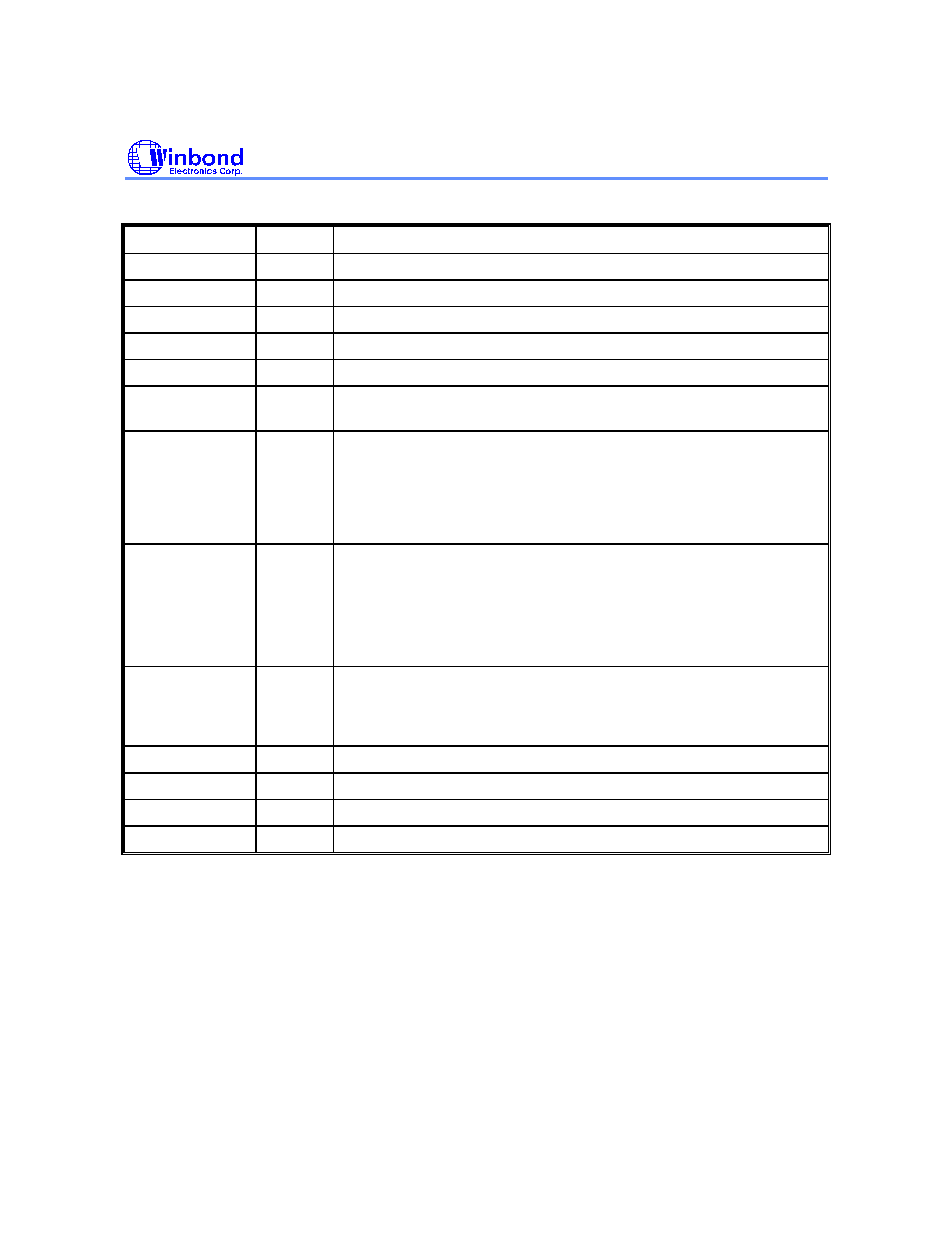
3. PIN DESCRIPTION
PIN NAME
I/O
FUNCTION
RESETB
In
IC reset input.
XIN
In
Sub-clock oscillation input. Only RC type is allowed.
XOUT
Out
Sub-clock oscillation output.
OSCI
In
Main-clock oscillation input.
OSCO
Out
Main-clock oscillation output.
OSCSEL
In
Pin selection of main-clock type. When OSCSEL is logic 1, Ring type
is used. When OSCSEL is logic 0, crystal type is used.
IP0[7:4]
(Expect
W566B100,
W566B120,
W566B150, &
W566B170)
In
General input port with pull-high selection. Each input pin can be
programmed to generate interrupt request and used to release IC
from HOLD/STOP mode.
IP0.6 can be used as the external clock source of the general timer
TimerG.
BP0[7:0]
I/O
General input/output pins. When used as output pin, it can be open≠
drain or CMOS type and it can sink 8mA for high-current application.
When used as input pin, there may have a pull-high option and
generate interrupt request to release IC from HOLD/STOP mode.
When BP0[7] is used as output pin, it can be the IR transmission
carrier for firmware IR application.
BP1[7:0]
I/O
General input/output pins. When used as output pin, it can be open≠
drain or CMOS type. When used as input pin, there may have a pull-
high option and generate interrupt request to release IC from
HOLD/STOP mode.
DAC
Out
Current type speaker output.
TEST
In
Test input. Do not connect during normal operation.
V
DD
Power Positive power supply.
V
SS
Power Negative power supply.