 | –≠–ª–µ–∫—Ç—Ä–æ–Ω–Ω—ã–π –∫–æ–º–ø–æ–Ω–µ–Ω—Ç: W83768 | –°–∫–∞—á–∞—Ç—å:  PDF PDF  ZIP ZIP |

W83768
I/O COUPLER
Publication Release Date: October 1994
- 1 -
Revision A1
GENERAL DESCRIPTION
The W83768 is an I/O-coupler chip that includes six line drivers (1488), ten line receivers (1489), two
timers (556), and one 244-type buffer block for game port signals. It also supports a power-down
control circuit to reduce power consumption. This chip is intended for use with an I/O controller, and it
is specifically designed to match the pin assignments of the Winbond Power I/O series. With this
chip, engineers can easily design an all-in-one I/O circuit for personal computer systems without using
any other TTL ICs.
FEATURES
∑
Six line drivers (1488), ten line receivers (1489), two timers (556), one buffer block for game port
signals
∑
Supports two RS232 serial ports and one game port control logic circuit
∑
Power-down control function available
∑
Four power supplies needed: 0V, +5V, +12V, and -12V
∑
48-pin QFP package
PIN CONFIGURATION
25
26
27
28
29
30
31
32
33
34
35
36
24
23
22
21
20
19
18
17
16
15
14
13
48
47
46
45
44
43
42
41
40
39
38
37
12
11
10
9
8
7
6
5
4
3
2
1
/
R
V
O
P
3
G
N
D
P
D
C
I
N
G
B
O
0
R
V
I
N
9
/
R
V
O
P
2
/
R
V
O
P
1
G
B
O
1
R
V
I
N
6
R
V
I
N
7
R
V
I
N
8
/
D
R
O
P
5
DROP4
DROP6
DROP2
DROP3
-12V
RVIN10
RVIN1
RVIN4
RVIN3
RVIN2
RVIN5
DROP1
M
R
S
D
5
G
P
O
0
+
1
2
V
G
P
O
1
S
D
4
S
D
1
S
D
0
/
R
V
O
P
7
/
R
V
O
P
8
/
R
V
O
P
9
/
R
V
O
P
1
0
RVOP4
RVOP5
RVOP6
DRIN1
DRIN2
DRIN3
GMRD
GMWR
DRIN4
DRIN5
DRIN6
+5V
W83768
- 2 -
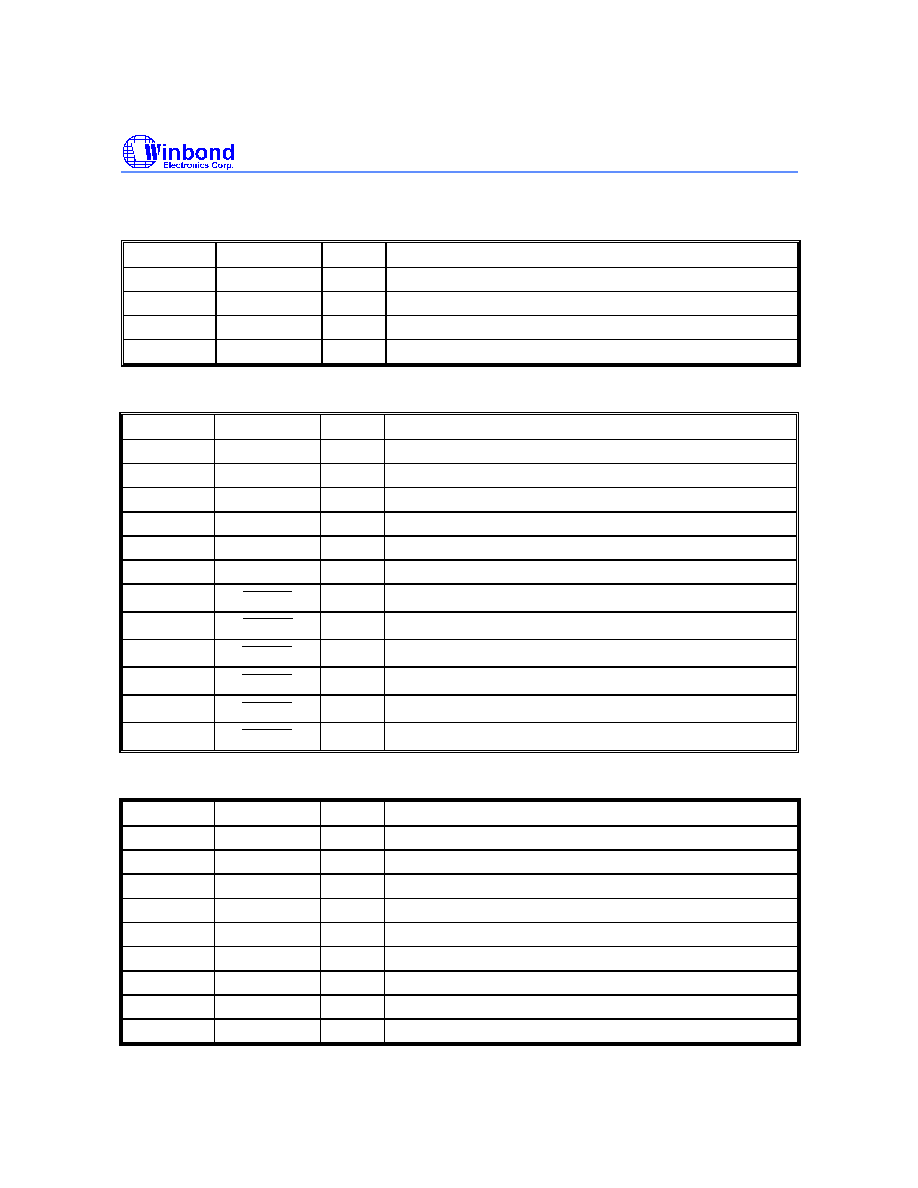
PIN DESCRIPTION
Power Pins
PIN NO.
SYMBOL
I/O
DESCRIPTION
36
GND
-
Ground
48
V
CC
-
+5V Power
12
V
DD
-
+12V Power
24
V
SS
-
-12V Power
Line Drivers
PIN NO.
SYMBOL
I/O
DESCRIPTION
38
DRIN1
I
Driver input 1
39
DRIN2
I
Driver input 2
40
DRIN3
I
Driver input 3
44
DRIN4
I
Driver input 4
45
DRIN5
I
Driver input 5
46
DRIN6
I
Driver input 6
13
DROP1
O
Driver output 1
18
DROP2
O
Driver output 2
14
DROP3
O
Driver output 3
22
DROP4
O
Driver output 4
27
DROP5
O
Driver output 5
21
DROP6
O
Driver output 6
Line Receivers
PIN NO.
SYMBOL
I/O
DESCRIPTION
20
RVIN1
I
Receiver input 1
16
RVIN2
I
Receiver input 2
17
RVIN3
I
Receiver input 3
19
RVIN4
I
Receiver input 4
15
RVIN5
I
Receiver input 5
28
RVIN6
I
Receiver input 6
26
RVIN7
I
Receiver input 7
25
RVIN8
I
Receiver input 8
29
RVIN9
I
Receiver input 9

W83768
Publication Release Date: October 1994
- 3 -
Revision A1
Line Receivers, continued
PIN NO.
SYMBOL
I/O
DESCRIPTION
23
RVIN10
I
Receiver input 10
33
RVOP1
I/O
During normal operations, this pin works as receiver output
#1. During power-on reset, this pin is used to select power-
down control (PDC) mode enable level.
When
RVOP1
is set to high at power-on, PDC is high
active. When
RVOP1
is set to low at power-on, PDC is low
active.
34
RVOP2
O
Receiver output 2
35
RVOP3
O
Receiver output 3
37
RVOP4
O
Receiver output 4
41
RVOP5
O
Receiver output 5
47
RVOP6
O
Receiver output 6
1
RVOP7
O
Receiver output 7
2
RVOP8
O
Receiver output 8
3
RVOP9
O
Receiver output 9
4
RVOP10
O
Receiver output 10
Game Port
PIN NO.
SYMBOL
I/O
DESCRIPTION
11
GPO0
I/O
Game port RC constant (open drain)
10
GPO1
I/O
Game port RC constant (open drain)
31
GBO0
I
Game port button input
30
GBO1
I
Game port button input
42
GMRD
I
Game port read. This pin is internally pulled-up to make it
convenient to disable the game port.
43
GMWR
I
Game port write
Control Signals
PIN NO.
SYMBOL
I/O
DESCRIPTION
5
MR
I
Master reset signal input
32
PDCIN
I
This pin is used to enable/disable the power-down function.
The active level of this pin depends on how pin
RVOP1
is
programmed at power-on. If
RVOP1
is set high at power-
on, for example, then setting PDCIN to high will cause the
W83768 to enter power-down mode.

W83768
- 4 -
Data Bus
PIN NO.
SYMBOL
I/O
DESCRIPTION
6
SD0
O
System data bit 0
7
SD1
O
System data bit 1
8
SD4
O
System data bit 4
9
SD5
O
System data bit 5
BLOCK DIAGRAM
74244
556
LINE DRIVER
1488
LINE RECEIVER
1489
SD0, SD1
SD4, SD5
GMRD
GMWR
DRIN1-6
RVOP1-10
RVIN1-10
DROP1-6
GBO1
GBO0
GPO1
GPO0
GPO1'
GPO0'
FUNCTIONAL DESCRIPTION
Block 74244
This 244-type block functions as a buffer for reading game port buttons GBO0 and GBO1 and the
status of block 556 output signals GPO0' and GPO1' on data bits 4, 5, 0, and 1, respectively.
Block 556
This block contains two independent 555-type timing circuits that are used to generate two separate
one-shot signals. With these two one-shot pulses, the RC inputs of the game port can easily be
measured. The
GMWR
signal is the trigger signal of block 556.

W83768
Publication Release Date: October 1994
- 5 -
Revision A1
Line Driver Block 1488
This block contains six line drivers that are designed to serve as an interface between data terminal
equipment and data communications equipment in conformance with the specifications of EIA
standard RS-232C. The power requirements are +12V, 0V, and -12V.
Line Receiver Block 1489
This block contains ten line receivers that are designed to serve as an interface between data
terminal equipment and data communications equipment in conformance with the specifications of
EIA standard RS-232C. The power requirements are +12V, 0V, and -12V.
Power-Down Control Mode
When pin PDCIN is set active (active high or low determined by RVOP1 at power-on reset), the
W83768 enters power-down mode, and all output buffers (SD0, SD1, SD4, SD5,
RVOP1 10
-
,
DROP1
6
-
) will enter tri-state to reduce power consumption.
ABSOLUTE MAXIMUM RATINGS
PARAMETER
RATING
UNIT
Power Supply Voltage
GND, V
CC
0 to 5.5
V
V
SS
, V
DD
-13 to 13
Input Voltage
Low Voltage
-0.5 to 7.0
V
High Voltage
-12 to 12
Operating Temperature
0 to 70
∞
C
Storage Temperature
-55 to 150
∞
C
Note: Exposure to conditions beyond those listed under Absolute Maximum Ratings may adversely affect the life and reliability of the
device.
DC CHARACTERISTICS
Ta = 0
∞
C to +70
∞
C, V
CC
= 5V, V
DD
= 12V, V
SS
= -12V, GND = 0V
PARAMETER
SYMBOL
MIN.
MAX.
NOTES
Input low voltage
V
IL
(TTL)
-0.3V
+0.6V
MR, GMRD, GMWR
Input high voltage
V
IH
(TTL)
+2.4V
V
CC
+0.3V
MR, GMRD, GMWR
Input low voltage
V
IL
(CMOS)
-0.3V
0.2 V
CC
DRIN1
-
6, GBO0
-
1, GPO0
-
1,
PDCIN

W83768
- 6 -
DC Characteristics, continued
PARAMETER
SYMBOL
MIN.
MAX.
NOTES
Input high voltage
V
IH
(CMOS)
+3.9V
V
CC
+0.3V
DRIN1
-
6, GBO0
-
1, GPO0
-
1,
PDCIN
Input low voltage
V
IL
(HI-V)
V
SS
GND
RVIN1
-
10
Input high voltage
V
IH
(HI-V)
2V
V
DD
RVIN1
-
10
Output low voltage
V
OL
-
0.4V
RVOP1 10
-
, SD0, SD1, SD4, SD5
Output high voltage
V
OH
+2.4V
-
RVOP1 10
-
, SD0, SD1, SD4, SD5
Output low voltage
V
OL
(HI-V)
V
SS
-2V
DROP1 6
-
Output high voltage
V
OH
(HI-V)
+2V
V
DD
DROP1 6
-
CURRENT LEVEL
SYMBOL
MAX.
MIN.
TYP.
I
IL
I
IH
I
OL
I
OH
I
OL
I
OH
MR
-20
µ
A
3
µ
A
-
-
-
-
PDCIN
-20
µ
A
3
µ
A
-
-
-
-
GMRD
,
GMWR
-20
µ
A
3
µ
A
-
-
-
-
GBO0, GBO1
-20
µ
A
3
µ
A
-
-
-
-
RVIN1
-
10
-1 mA
3
µ
A
-
-
-
-
GPO0, GPO1
-
-
1.5 mA
-
2 mA
-
SD0, SD1, SD4, SD5
-
-
5.5 mA
4 mA
8 mA
6 mA
RVOP1 10
-
-
-
2 mA
2 mA
3 mA
3 mA
DROP1 6
-
-
-
10 mA
10 mA
14 mA
16 mA
AC CHARACTERISTICS
PARAMETER
SYMBOL
MIN.
TYP.
MAX.
UNIT
1488 tpLH
DRIN1
-
6
-
60
90
nS
1488 tpHL
DROP1 6
-
-
60
90
nS
1489 tpLH
RVIN1
-
10
-
60
90
nS
1489 tpHL
RVOP1 10
-
-
60
90
nS
tD
SD0, SD1, SD4, SD5
-
90
120
nS

W83768
Publication Release Date: October 1994
- 7 -
Revision A1
TIMING WAVEFORMS
Floating
Floating
Data Valid
tD
T= RC
+5V
0V
+12V
-12V
+12V
-12V
+5V
0V
tpLH
tpHL
tpLH
tpHL
CV= 3.3V
IN
OUT
IN
OUT
DRIN1-6
RVIN1-10
RVOP1-10
GPO0
GPO1
GPO0'
GPO1'
SD0, SD1
SD4, SD5
DROP1-6
GMWR
GMRD
Driver Timing
Receiver Timing
Timer Timing

W83768
- 8 -
PACKAGE DIMENSIONS
48-lead QFP
2
1
A
H
D
D
e
b
E
H
E
y
A
A
Seating Plane
L
L
1
See Detail F
Detail F
c
1
12
13
24
25
36
37
48
1. Dimensions D & E do not include interlead
flash.
2. Dimension b does not include dambar
protrusion/intrusion.
3. Controlling dimension: Millimeters
4. General appearance spec. should be based
on final visual inspection spec.
0.25
0.10
0.010
0.004
Notes:
Symbol
Min.
Nom.
Max.
Max.
Nom.
Min.
Dimension in inch
Dimension in mm
A
b
c
D
e
H
D
H
E
L
y
0
A
A
L
1
1
2
E
0.006
0.15
0.070
1.78
0.004
0.052
0.011
0.057
0.013
0.062
0.017
1.32
0.28
0.10
1.45
0.33
1.58
0.43
0.389
0.618
0.067
0.118
0.006
0
15
0.394
0.630
0.075
0.399
0.642
0.083
9.87
0.75
15.70
1.70
3.00
10.00
16.00
1.90
10.13
16.30
2.10
0.399
0.394
0.389
0.642
0.630
0.618
16.30
16.00
15.70
10.13
10.00
9.87
15
0
0.15
0.024
0.036
0.126
0.110
0.60
0.90
2.79
3.20
---
---
---
---
---
---
---
---
---
---
---
---
---
---
Headquarters
No. 4, Creation Rd. III,
Science-Based Industrial Park,
Hsinchu, Taiwan
TEL: 886-3-5770066
FAX: 886-3-5792646
http://www.winbond.com.tw/
Voice & Fax-on-demand: 886-2-7197006
Taipei Office
11F, No. 115, Sec. 3, Min-Sheng East Rd.,
Taipei, Taiwan
TEL: 886-2-7190505
FAX: 886-2-7197502
Winbond Electronics (H.K.) Ltd.
Rm. 803, World Trade Square, Tower II,
123 Hoi Bun Rd., Kwun Tong,
Kowloon, Hong Kong
TEL: 852-27516023
FAX: 852-27552064
Winbond Electronics North America Corp.
Winbond Memory Lab.
Winbond Microelectronics Corp.
Winbond Systems Lab.
2730 Orchard Parkway, San Jose,
CA 95134, U.S.A.
TEL: 1-408-9436666
FAX: 1-408-9436668
Note: All data and specifications are subject to change without notice.