
W90220F
1
Version 0.84
The above information is the exclusive intellectual property of Winbond Electroncs Corp. and shall not be dsiclosed or distributed or reproduced without permission from
Winbond.
W90220F
PA-RISC Embedded Controller
Version 0.84
March 1999

W90220F
2
Version 0.84
The above information is the exclusive intellectual property of Winbond Electroncs Corp. and shall not be dsiclosed or distributed or reproduced without permission from
Winbond.
Table of Contents
TABLE OF CONTENTS
1. OVERVIEW
2. FEATURES
3. PIN CONFIGURATION
3.1 Pin Diagram
3.2 Detailed Pin Descriptions
4. CPU CORE
4.1 Overview
4.2 Block diagram
4.3 Features
4.4 PA-RISC Architecture
4.4.1 CPU Resources
4.4.2 Addressing Mode & Memory Map
4.4.3 Branch Control
4.4.4 Interrupt Control
4.5 Pipeline Operation
4.6 Implementation Dependent features
4.6.1 MultiMedia Extension Instruction Set
4.6.2 MAC unit and Releated Instruction Set
4.6.3 Diagnostic Instruction Set
4.6.4 Flush Instruction/Data Cache & Branch-Target-Buffer (BTB)
4.6.5 Level-0 Debug SFU
4.7 Power Management Unit
4.8 Serial ICE interface
5. MEGACELLS
5.1 Functional Descriptions
5.1.1 Memory Controller
5.1.2 DMA Controller
5.1.3 PCI Bridge
5.1.4 Parallel Port Interface (PPI)
5.1.5 UART

W90220F
3
Version 0.84
The above information is the exclusive intellectual property of Winbond Electroncs Corp. and shall not be dsiclosed or distributed or reproduced without permission from
Winbond.
5.1.6 Synchronous Serial Port Interface (SSI)
5.1.7 Timer Channels
5.2 Register Definitions
5.2.1 Memory Controller
5.2.2 DMA Controller
5.2.3 PCI Bridge
5.2.4 Parallel Port Interface (PPI)
5.2.5 UART
5.2.6 Synchronous Serial Port Interface (SSI)
5.2.7 Timer Channels
6. ELECTRICAL SPECIFICATIONS
6.1 Absolute Maximum Ratings
6.2 DC Specifications
6.3 AC Specifications
6.3.1 Memory Controller
6.3.2 DMA Controller
6.3.3 PCI Bridge
6.3.4 Parallel Port Interface (PPI)
6.3.5 UART
6.3.6 Synchronous Serial Port Interface (SSI)
6.3.7 Timer Channels
7. PACKAGE DIMENSIONS

W90220F
4
Version 0.84
The above information is the exclusive intellectual property of Winbond Electroncs Corp. and shall not be dsiclosed or distributed or reproduced without permission from
Winbond.
1. OVERVIEW
The W90220 is a high performance, highly integrated 32-bit processor intended for a wide range of
embedded applications, such as videophone, internet devices, internetworking platform. Fig 1-1 shows a
block diagram of the overall system. The W90220 consists of a 32-bit PA-RISC core, memory controller
and integrated logics for I/O modules
The PA-RISC core is equipped with 4 KBytes of instruction cache memory and 4 KBytes of data cache
memory augmented with a dual-cycle multiply/accumulate module running up to 150 MHz. It allows to
implement integrated DSP functions like software modem for high-performance standard data and fax
protocols. A flexible power management scheme (under software control) and lots of low power circuits
have been used to eliminate the chip's power consumption. The W90220 consume only 375 mA at its
maximum speed (150 MHz) on a full-load system.
The chip provides two 8-bit DMA channels, four 16-bit IDE I/O channels, a PCI bridge supporting up to
four external PCI masters, a IEEE-1284 compliant parallel port interface (PPI), two RS232 type universal
asynchronous serial port (UART), two timer channels, a flexible synchronous interface (SSI) connecting to
an external audio or telephony codec devices, a proprietary serial ICE interface (SP-ICE) for software
development and debugging.
The chip has a high performance memory controller. The types of external memory devices supported
include dynamic random access memory (DRAM), Extended data out dynamic random access memory
(EDO-DRAM), static random access memory (SRAM), Flash memory as well as read-only memory
(ROM).
PCI
Bridge
Memory
Controller
DMA
Controller
Parallel Port
Interface
UART
(x2)
Sync. Serial
Port
Timer (x2)
32-bit Internal DMA bus
32-bit CPU Internal Bus
6-Stage Integer Pipeline
Instr. Cache
RAM
Internal Bus Interface Unit
PLL
Data Cache
RAM
Branch Table
RAM
OSC
(14.318 Mhz)
CPUCLK
PCI Bus
DRAM/Flash/
ROM Port
8-bit-DMA/
16-bit-IO Bus
Power Mang.
Unit
Serial ICE
Unit
Serial ICE
Bus
3
Fig 1-1 : W90220 Internal Block Diagram

W90220F
5
Version 0.84
The above information is the exclusive intellectual property of Winbond Electroncs Corp. and shall not be dsiclosed or distributed or reproduced without permission from
Winbond.
2. FEATURES
�
PQFP 208-pin package
�
High level of integration
�
minimal number of inter-chip connections
�
32-bit PA-RISC core with cache memory, multiply-accumulate module and flexible power management
unit
�
DMA controller provides two external 8-bit DMA slots and four 16-bit IDE-IO slots
�
memory controller supports four banks of EDO- or fast-page-mode DRAM, Flash, ROM and SRAM
�
an PCI bridge supports four PCI master devices
�
an IEEE-1284 compliant parallel port connecting an external printer
�
two RS-232 compliant serial port connecting external MODEM controller or other serial devices
�
a synchronous serial port connecting external audio or telephony codec devices
�
two timer channels for general purpose usage
�
High performance and low power consumption
�
0.35-micron single-poly-triple-metal CMOS process
�
split rail design (3.3V/5V IO and 3.3V core)
�
maximal operation frequency : 150 Mhz
�
typical active current : 2.5mA/Mhz
�
typical suspend current (PLL turn off) : -
�
fully static design, afford dynamic turn on/off cpu clock or PLL module+
�
programable standby clock to reduce standby current
�
real time clock and UART baud rate base on 14.318 Mhz
�
A flexible hardware serial ICE port for monitor/update cpu status at any time

W90220F
6
Version 0.84
The above information is the exclusive intellectual property of Winbond Electroncs Corp. and shall not be dsiclosed or distributed or reproduced without permission from
Winbond.
3. PIN CONFIGURATION
The W90220 family of embedded controllers is available in a 208-pin quad flat pack (PQFP) device configuration,
shown below.
3.1. PIN DIAGRAM
E
D
4
E
D
5
E
D
6
E
D
7
V
D
D
i
D
A
C
K
1
D
A
C
K
0
V
D
D
p
O
S
C
V
S
S
p
C
S
1
C
S
0
D
R
E
Q
1
D
R
E
Q
0
D
D
0
D
D
1
D
D
2
D
D
3
D
D
4
D
D
5
D
D
6
D
D
7
S
D
O
V
S
S
i
S
Y
N
C
V
S
S
p
S
C
L
K
S
D
I
V
D
D
p
T
C
1
V
D
D
5
V
T
C
0
I
O
R
#
I
O
W
#
D
M
A
R
D
Y
N
A
U
F
D
N
I
N
I
T
V
S
S
i
S
E
L
O
E
D
0
E
D
1
E
D
2
E
D
3
S
E
L
P
E
N
A
C
K
N
F
A
U
L
T
V
D
D
p
B
U
S
Y
N
S
T
B
V
S
S
p
R
C
S
1
#
R
C
S
2
#
R
C
S
3
#
M
A
0
M
A
1
R
O
M
E
N
M
A
2
M
A
3
M
A
4
V
D
D
i
M
A
5
M
A
6
V
S
S
p
P
W
R
O
N
V
D
D
p
M
A
7
V
S
S
i
M
A
8
M
A
9
M
A
1
0
M
A
1
1
R
O
M
R
W
#
R
O
M
O
E
#
G
N
T
0
#
G
N
T
1
#
P
R
E
Q
0
#
P
R
E
Q
1
#
P
D
A
3
1
P
D
A
3
0
P
D
A
2
9
V
S
S
p
P
D
A
2
8
V
D
D
p
P
D
A
2
7
W
A
K
E
U
p
P
C
I
C
L
K
V
S
S
p
R
A
S
0
#
V
D
D
5
V
R
A
S
1
#
R
A
S
2
#
R
A
S
3
#
R
C
S
0
#
S
I
N
0
S
O
U
T
0
D
T
R
0
N
R
T
S
0
N
S
O
U
T
1
S
I
N
1
P
C
I
R
S
T
V
D
D
p
I
N
T
D
#
R
E
S
U
M
E
P D A 9
P D A 1 0
V S S p
P D A 1 1
P D A 1 2
P D A 1 3
P D A 1 4
P D A 1 5
C O M B E 1 #
P P A R #
S E R R #
P E R R #
S T O P #
V D D i
D E V S E L #
V D D p
T R D Y #
V S S p
I R D Y #
F R A M E #
C O M B E 2 #
P D A 1 6
P D A 1 7
P D A 1 8
P D A 1 9
V S S i
P D A 2 0
V D D p
P D A 2 1
V S S p
P D A 2 2
P D A 2 3
C O M B E 3 #
P D A 2 4
P D A 2 5
P D A 4
V S S i
P D A 5
P D A 6
P D A 7
C O M B E 0 #
P D A 8
V D D p
I N T C #
I N T B #
I N T A #
P D A 0
P D A 1
P D A 2
P D A 3
V S S p
P D A 2 6
1 0 0
M D 1 3
M D 1 4
M D 1 5
M D 1 6
M D 1 7
M D 1 8
M D 1 9
V S S p
M D 2 0
M D 2 1
V D D i
M D 2 2
M D 2 3
M D 2 4
M D 2 5
M D 2 6
M D 2 7
M D 2 8
M D 2 9
V D D p
M D 3 0
V S S p
M D 3 1
V S S i
C A S 0 #
V D D l
P L L O S C
V S S l
C A S 1 #
C A S 2 #
C A S 3 #
W E #
D C D 0 #
R I 0 #
D S R 0 #
V S S i
M D 8
V S S p
M D 9
V D D p
M D 1 0
M D 1 1
M D 1 2
M D 0
M D 1
M D 2
M D 3
M D 4
M D 5
M D 6
M D 7
C T S 0 #
1 6 0
8 0
1 8 0
1 7 0
9 0
2 0 0
1 9 0
6 0
7 0
1
5
0
1
4
0
1
3
0
1
2
0
1
1
0
2
0
3
0
1
0
4
0
1
5
0
W 9 0 2 2 0 F
( 2 0 8 - p i n P Q F P )

W90220F
7
Version 0.84
The above information is the exclusive intellectual property of Winbond Electroncs Corp. and shall not be dsiclosed or distributed or reproduced without permission from
Winbond.
3.2 DETAILED PIN DESCRIPTIONS
The following abbreviations are used for pin types in the following sections : (I) indicates inputs; (O) indicates
outputs; (I/O) indicates a bidirectional signal; (TS) indicates three-state; (OC) indicates open collector.
PIN Name
DIR
PIN #
DESCRIPTION
CPU Signal
PWRON
I
30
CPU Power-On reset input, high active
PLLOSC
I
199
14.318Mhz Oscillator input for internal PLL
OSC
I
132
14.318Mhz Oscillator input for Timer, UART
PCI LOCAL BUS
for more detail description of the PCI signals please refer to the PCI LOCAL
BUS SPECIFICATION
INTA#
INTB#
INTC#
INTD#
I
102
103
104
105
PCI Interrupt input, level senstive, low active signal. Once
the INTx# signal is asserted, it remains asserted until the
device driver clear the pending request. When the request is
cleared, the device deasserts its INTx# signal.
PREQ0#
PREQ1#
I
42
43
PCI Request input, indicates to the PCI arbiter that this agent
desires use of the bus.
GNT0#
GNT1#
O
40
41
PCI Grant output, indicates to the agent that access to the
bus has been granted.
PCIRST#
O
7
PCI Reset output, is used to bring PCI-specific registers,
sequencers, and signals to a consistent state. Low active.
PCICLK
O
9
PCI Clock output, provides timing for all transactions on PCI
and is an input to every PCI device.
SERR#
I
78
PCI System Error is for reporting address parity errors, data
parity errors on the Special Cycle command, or any other
system error where the result will be catastrophic. The
assertion of SERR# is synchronous to the clock and meets
the setup and hold times of all bused signals.
PERR#
I/O
77
PCI Parity Error is only for the reporting of data parity errors
during all PCI transactions except a Special Cycle. The
PERR# pin is sustained tri-state and must be driven active
by the agent receiving data two clocks following the data
when a data parity error is detected. The minimum duration
of PERR# is one clock for each data phase that a data parity
error is detected. An agent cannot report a PERR# until it
has claimed the access by asserting DEVSEL# (for a target)
and completed a data phase or is the master of the current
transaction.

W90220F
8
Version 0.84
The above information is the exclusive intellectual property of Winbond Electroncs Corp. and shall not be dsiclosed or distributed or reproduced without permission from
Winbond.
PDA[31:0]
I/O
44-46, 48, 50,
53-55, 57, 58,
60, 62, 64-67,
81-85, 87, 88,
90, 92-94, 96,
98-101,
PCI tri-state Address/Data bus, Address and Data are
multiplexed on the same PCI pins. A bus transaction consists
of an address phase followed by one or more data phases.
PCI supports both read and write bursts. The address phase
is the clock cycle in which FRAME# is asserted. During the
address phase PDA[31:0] contain a physical address. During
data phases PDA[7:0] contain the least significant byte (lsb)
and PDA[31:24] contain the most significant byte (msb).
Write data is stable and valid when IRDY# is asserted and
read data is stable and valid when TRDY# is asserted. Data
is transferred during those clocks where both IRDY# and
TRDY# are asserted.
STOP#
I/O
76
PCI Stop indicates the current target is requesting the master
to stop the current transaction.
TRDY#
I/O
72
PCI Target Ready indicates the selected device
ability to
complete the current data phase of the transaction. A data
phase is completed on any clock both TRDY# and IRDY# are
sampled asserted. During a read, TRDY# indicates that valid
data is present on PDA[31:0]. During a write, it indicates the
target is prepared to accept data. Wait cycles are inserted
until both IRDY# and TRDY# are asserted together.
DEVSEL#
I/O
74
PCI Device Select, when actively driven, indicates the
driving device has decoded its address as the target of the
current access. As an input, DEVSEL# indicates whether any
device on the bus has been selected.
C/BE[3:0]#
I/O
56,68,80,91
PCI Bus Command and Byte Enables are multiplexed on the
same PCI pins. During the address phase of a transaction,
C/BE[3:0]# define the bus command. During the data phase
C/BE[3:0]# are used as Byte Enables. The Byte Enables are
valid for the entire data phase and determine which byte
lanes carry meaningful data. C/BE[0]# applies to byte 0 (lsb)
and C/BE[3]# applies to byte 3 (msb).
FRAME#
I/O
69
PCI Cycle Frame is driven by the current master to indicate
the beginning and duration of an access. FRAME# is
asserted to indicate a bus transaction is beginning. While
FRAME# is asserted, data transfers continue. When FRAM#
is deasserted, the transaction is in the final data phase or has
completed.
IRDY#
I/O
70
PCI Initiator Ready indicates the bus master
ability to
complete the current data phase of the transaction. A data
phase is completed on any clock both IRDY# and TRDY# are
sampled asserted. During a write, IRDY# indicates that valid
data is present on PDA[31:0]. During a read, it indicates the
master is prepared to accept data. Wait cycles are inserted
until both IRDY# and TRDY# are asserted together.

W90220F
9
Version 0.84
The above information is the exclusive intellectual property of Winbond Electroncs Corp. and shall not be dsiclosed or distributed or reproduced without permission from
Winbond.
PPAR
I/O
79
PCI Parity is even parity across PDA[31:0] and C/BE[3:0]#.
PPAR is stable and valid one clock after the address phase.
For data phases, PPAR is stable and valid one clock after
either IRDY# is asserted on a write transaction or TRDY# is
asserted on a read transaction. (PPAR has the same timing
as PDA[31:0], but it is delayed by one clock.) The mater
drives PPAR for address and write data phases; the target
drives PPAR for read data phase.
DMA Interface
DREQ0
DREQ1
I
127
128
DMA Request signals request an external transfer on DMA
channel 0 (DREQ0) or DMA channel 1 (DREQ1).
DACK0
DACK1
O
134
135
DMA Acknowledge signals acknowledge an external transfer
on DMA channel 0 (DREQ0) or DMA channel 1 (DREQ1).
DMARDY
I
106
DMA Device Ready signal is used to extend the length of
DMA bus cycles. If a device wants to extend the DMA bus
cycles, it will force the DMARDY signal low when it decodes
its address and receives a IOR or IOW command.
CS0
CS1
O
129
130
DMA Chip Select signals select the corresponding I/O
devices for programming or DMA transfers.
IOR
O
108
DMA I/O read signal is used to indicate to the I/O device that
the present bus cycle is an I/O read cycle.
IOW
O
107
DMA I/O write signal is used to indicate to the I/O device that
the present bus cycle is an I/O write cycle.
TC0
TC1
O
109
111
Terminal count for DMA channels, the pin is driven active for
one clock when byte count reaches zero and after the last
transfer for a DAM has completed.
DD[0:7]
I/O
126-119
8-bit DMA I/O Data bus, bit 0 is the most significant bit.
ECP Interface
For more detail description of the ECP interface signals,
please refer to the IEEE P1284 Standard
Busy
I
151
ECP busy input signal
nFault
I
153
ECP fault input
nAck
I
154
ECP acknowledge input
PError
I
155
ECP parity error
Select
I
156
ECP Select
nSelectIn
O
145
ECP select output
nInit
O
147
ECP initialization
nAutoFd
O
148
ECP Autofeed
nStrobe
O
150
ECP Strobe
ED[0:7]
I/O
144-137
Bi-directional ECP Data bus, ED[0] is the most significant bit
(msb).
Memory Controller Interface
RAS#[0:1]
O
11, 13
DRAM Row Address Strobe, Banks 0-1. These signals are
used to select the DRAM row address. A High-to-Low
transition on one of these signals causes a DRAM in the
corresponding bank to latch the row address and begin an
access.

W90220F
10
Version 0.84
The above information is the exclusive intellectual property of Winbond Electroncs Corp. and shall not be dsiclosed or distributed or reproduced without permission from
Winbond.
RAS#[2:3]/
PREQ#[2:3]
I/O
14, 15
If MD[20] is pull down, these pins serve RAS signals for
external DRAM's bank 2 and 3.
If MD[20] is pull high, these pins serve as "PCI Request 2
and 3" indicate to the PCI arbiter that the masters desires
use of the bus
CAS#[0:3]
O
197, 201-203
DRAM Column Address Strobes, Byte 0-3. These signals are
used to select the DRAM column address. A High-to-Low
transition on these signals causes the DRAM selected by
RAS#[0:3] to latch the column address and complete the
access.
WE#
O
204
DRAM Write Enable signal is used to write the selected
DRAM bank.
RCS#[0:1]
O
16, 17
ROM Chip Selects, Banks 0-1. A low level on one of these
signals selects the memory devices in the corresponding
ROM bank.
RCS#[2:3]/
GNT#[2:3]
O
18, 19
If MD[20] is pull down, these pins serve ROM "Chip select"
for
bank 2 and 3.
If MD[20] is pull high, these pins serve as "PCI Grant 2 and
3" indicate to the PCI masters that access to the PCI bus has
been granted.
ROMEN
O
22
ROM Address Latch, ROM address are divided into two
portions, higher address bits and lower address bits, the
address will be put out on the MA bus in two consecutive
cycles. The ROMEN signal is used to latch the higher
address bits in the first ROM address cycle.
ROMRW#
O
38
FLASH ROM write enable. This signal is used to write data
into the mrmory in a ROM bank (such as Flash ROM).
ROMOE#
O
39
ROM output enable. This signal enables the selected ROM
Bank to drive the MD bus.
MA[0:11]/
DA[0:11]
O
20-21, 23-25,
27-28, 32, 34-
37
Memory controller Memory Address bus. For DRAM access,
MA[0:11] is the DRAM row address and the DRAM column
address. For ROM/FLASH ROM access, MA[0:11] is the
higher portion ROM space address bits in the first ROM
address cycle, and the lower portion ROM space address bits
after the first ROM address cycle. During DMA I/O cycles,
these pins also serve as DMA address bus. MA[0] is the
most significant bit (msb).
MD[0:7]
I/O
157-164
Memory controller Data bus bit 0-7 for both DRAM data and
ROM space data. Bit 0 is the most significant bit (msb).
MD[8:15]/
DD[8:15]
I/O
166, 168,
170-175
Memory controller Data bus bit 8-15for both DRAM data and
ROM space data. During DMA cycles, these pins also serve
as DMA data bus bit 8-15 for 16-bit DMA transfering. Bit 8 is
the most significant bit (msb).
MD[16:31]
I/O
176-179,
181,182,184-
191,193,195
Memory controller Data bus bit 16-31 for both DRAM data
and ROM space data. Bit 16 is the most significant bit (msb).
COM1 Serial Port Signal
SIN1
I
1
COM1 serial data input from the communication link (modem
or peripheral device).

W90220F
11
Version 0.84
The above information is the exclusive intellectual property of Winbond Electroncs Corp. and shall not be dsiclosed or distributed or reproduced without permission from
Winbond.
SOUT1
O
2
COM1 serial data output to the communication link (modem
or peripheral device).
CTS1n
I
208
COM1 clear to send signal
DSR1n
I
207
COM1 data set ready
DTR1n
O
3
COM1 data terminal ready
RTS1n
O
4
COM1 request to send
DCD1n
I
205
COM1 data carrier detect
RIN1n
I
206
COM1 ring indicator
COM2 Serial Port Signal
SIN2
I
6
COM2 serial data input from the communication link (modem
or peripheral device).
SOUT2
O
5
COM2 serial data output to the communication link (modem
or peripheral device).
Synchronous Serial Port Signal
SDI
I
113
Serial data-in from a external codec device
SDO
O
118
Serial data-out to a exteral codec device
SYNC
I/O
116
Frame sync of SDI/SDO. This signal is an input signal during
"slave mode" or output signal during "master mode"
SCLK
I/O
114
Serial Clock for SDI/SDO transfering. This signal is an input
signal during "slave mode" or output signal during "master
mode"
Miscellaneous
WAKEUP
/INTR0
I
51
If MD[24] is pull down, this pin serves as an external interrupt
request. A active high-state in this pin will make EIER[12] be
set. In this mode, this pin can also serve as an interrupt
request pin for an IDE slot.
If MD[24] is pull high, this pin serves a "resume" request to
wake up the chip from "DOZE" mode.
RESUME
/INTR1
I
52
If MD[24] is pull down, this pin serves as an external interrupt
request. A active high-state in this pin will make EIER[13] be
set. In this mode, this pin can also serve as an interrupt
request pin for an IDE slot.
If MD[24] is pull high, this pin serves a "resume" request to
wake up the chip from "SLEEP" mode.
Power/Ground pin
VDD5V
I
12,110
5.0V Vdd (for a mixed 5.0V/3.3V enviornment)
VDDp
I
8,31,49,61,73
,89,112,133,
152,169,192
Global 3.3V Vdd
VDDi
I
26,75,136,18
3
3.3V Vdd (for internal logic only)
VDDl
I
198
3.3V Vdd (for internal PLL logic)
VSSl
I
200
VSS (for internal PLL logic)
VSSi
I
33,63,95,117,
146,165,196,
VSS (for internal logic)
VSSp
I
10,29,47,59,
71,86,97,115,
131,149,167,
180,194
Global VSS

W90220F
12
Version 0.84
The above information is the exclusive intellectual property of Winbond Electroncs Corp. and shall not be dsiclosed or distributed or reproduced without permission from
Winbond.
4 CPU CORE
4.1 OVERVIEW
(Left for Blank)
4.2 BLOCK DIAGRAM
(Left for Blank)
4.3 FEATURES
�
Base on PA-RISC 1.1 level-0 architecture
�
32-bit integer instruction set and register files
�
Maximum 150Mhz operation frequency
�
3.3V and 0.01W/Mhz at full speed operation
�
On-chip power management
- Build-in software-independent `dynamic power-down mode`
- Programable `stand-by ` and `sleep ` mode
- Specific instruction to assist power-down control and ICE function
�
High-speed 32-bit integer pipeline design
- 6 stages for Load/Store instructions
- 5 stages for other instructions
�
On-chip cache memory
- 4KB, direct-map instruction cache and 4KB, 4-way set-associative data cache
- Write-through and write-back support for data cache
- 1 level read buffer and wrap-arround support in each cache
- l level write buffer and hit-under-miss support in data cache
- Cache-locking support in instruction cache
�
Dynamic branch prediction

W90220F
13
Version 0.84
The above information is the exclusive intellectual property of Winbond Electroncs Corp. and shall not be dsiclosed or distributed or reproduced without permission from
Winbond.
- Build-in 1-level 256 entry, 4-way set-associative (LRU) Branch-Target-Buffer to improve branch
prediction rate and accelerate pipeline throughput
�
Two high speed (12ns) 16-bit MACs (or one 32-bit MAC) and multimedia extended instructions have been
built-in for DSP releated calculation
�
Specific serial-ICE-interface to facilitate chip debuging and software development
4.4 PA-RISC ARCHITECTURE
4.4.1 CPU RESOURCES
(Left for Blank)
4.4.2 ADDRESSING MODES & MEMORY MAP
(Left for Blank)
4.4.3 BRANCH CONTROL
(Left for Blank)
4.4.4 INTERRUPT CONTROL
(Left for Blank)
4.5 PIPELINE OPERATION
(Left for Blank)
4.6 IMPLEMENTATION DEPENDENT FEATURES
4.6.1 MULTIMEDIA ENTENSION INSTRUCTION SET
(Left for Blank)
4.6.2 MAC UNIT AND RELEATED INSTRUCTION SET
(Left for Blank)

W90220F
14
Version 0.84
The above information is the exclusive intellectual property of Winbond Electroncs Corp. and shall not be dsiclosed or distributed or reproduced without permission from
Winbond.
4.6.3 DIAGNOSTIC INSTRUCTION SET
(Left for Blank)
4.6.4 FLUSH INSTRUCTION/DATA CACHE & BTB
(Left for Blank)
4.6.5 LEVEL-0 DEBUG SFU
(Left for Blank)
4.7 POWER MANAGEMENT UNIT
(Left for Blank)
4.8 SP-ICE INTERFACE
(Left for Blank)

W90220F
15
Version 0.84
The above information is the exclusive intellectual property of Winbond Electroncs Corp. and shall not be dsiclosed or distributed or reproduced without permission from
Winbond.
5 MEGACELLS
5.1 FUNCTIONAL DESCRIPTIONS
5.1.1 MEMORY CONTROLLER
Overview :
(Left for Blank)
Block Diagram :
(Left for Blank)
Features :
�
supports up to 4 banks of FPM- (fast page mode) or EDO-DRAM (SIMM)
�
supports up to 4 banks of ROM or Flash memory
�
optional parity bits for each data bytes
�
CAS#-befor-RAS# refresh cycles for DRAM module
�
programmable RAS#/CAS# timing for DRAM access
�
programmable wait states for ROM and Flash memory access
Related Pins :
(Left for Blank)
Operation Modes :
(Left for Blank)
5.1.2 DMA CONTROLLER
Overview :
(Left for Blank)
Block Diagram :
(Left for Blank)
Features :
�
provides two channels for external devices to do 8-bit dma io-to-memory transfer
�
flexible block-transfer mode and demand mode are supported
�
provides two 16-bit IDE IO-channels connecting IDE devices
�
provides 8-bit io-to-memory or memory-to-io transfer mode
�
provides 8-, 16- and 32-bit memory-to-memory transfer modes

W90220F
16
Version 0.84
The above information is the exclusive intellectual property of Winbond Electroncs Corp. and shall not be dsiclosed or distributed or reproduced without permission from
Winbond.
�
dma transfer between pci memory to/from system memory are also support
�
4 words (16 bytes) memory burst-access; linear burst order
�
build-in 4-words data FIFO to accelerate memory access
�
the starting address of source and target shall be halfword boundary for 16-bit memory transfer and word
boundary for 32-bit memory transfer
Related Pins :
There are 19 pins allocated for two external dma slots to do 8-bit io-to-memory dma transfer. These pins include 8-
bit bi-directional data bus as well as 11control/status pins.
- DREQ0, DREQ1 (input) :
Set high by external dma devices of slot 0 and slot 1 respectively to request dma 8-bit io-to-memory transfer.
The DREQ(s) shall keep asserted (logic 1) during "demand mode" transfering, while during "block mode"
transfering the DREQ(s) shall be deasserted (logic 0) after their corresponding DACK(s) is granted and before
the end of dma block transfering.
- DACK0, DACK1 (output) :
Set high by the dma controller to acknowledge the dma DREQ(s) from dma slot 0 and slot1 respectively.
Whenever DACK(s) is set high, the dma transfer is on-going.
- TC0, TC1 (output) :
At the end of the last byte of dma transfer, the TC(s) will be pulse high for 1 system clock immediately
indicating that dma transfer is finished.
- DMARDY (input) :
This signal is used by external dma devices to insert wait states when the devices being progrmming by cpu.
DMARDY is an open collector signal which shall be pull-up externally (default "don't insert any wait states").
If any devices need to lengthen the IOR or IOW cycle, it must drive DMARDY to logic high within one system
clock after IOR or IOW signal being set high.
- IOR (output) :
This signal is pulsed high indicating an IO read command cycle is on-going whether in cpu mode (DACK(s)
= 0s) or in dma mode (DACK(s) = 1).
- IOW (output) :
This signal is pulsed high indicating an IO write command cycle is on-going whether in cpu mode (DACK(s)
= 0s) or in dma mode (DACK(s) = 1).
- CS0, CS1 (output) :
These two signals are Chip Selects of dma slot 0 and slot 1. As dma controller wants to programming dma
devices, it must drive the corresponding CS(s) to logic high.
- DD[0:7] (in/out) :
Birdirectional 8-bit data bus with bit 0 is the most significant bit.
Operation Modes :
(Left for Blank)

W90220F
17
Version 0.84
The above information is the exclusive intellectual property of Winbond Electroncs Corp. and shall not be dsiclosed or distributed or reproduced without permission from
Winbond.
5.1.3 PCI BRIDGE
Overview :
(Left for Blank)
Block Diagram :
(Left for Blank)
Features :
�
supports "long framing" and "short framing" (synchronous, frame-based protocol)
�
provides "master mode" and "slave mode"
�
build-in two 48x16 (or 24x32) data fifo to accelerate transmit/receive operation
�
programable data bits per one frame (sampling rate) : 1 ~ 256 bits/frame
�
programable data bits per word (resolution of each sampling) : 1 ~ 32 bits/word
�
programable multi-word (per frame) transfer : 1 ~ 16 words/frame
Related Pins :
(Left for Blank)
Operation Modes :
(Left for Blank)
5.1.4 PARALLEL PORT INTERFACE
Overview :
(Left for Blank)
Block Diagram :
(Left for Blank)
Features :
�
supports all IEEE P1284 transfer modes including :
- Compatible (centronic) mode (forward channel)
- Nibble mode (reverse channel, compatible with all existing PC hosts - relies on software control)
- Byte mode (reverse channel, compatible with IBM PS/2 host)
- EPP mode (bi-directional half-duplex channel - relies on software control)
- ECP mode (fast bi-directional half-duplex channel)
�
Host-side design
�
Provide a special operation mode to emulate peripheral-side centronic device
�
Build-in one 16bytes FIFO to accelerate ECP mode and centronic forward transfer
�
Provide DMA capability to accelerate moving data from parallel port interface to system memory
�
ECP mode is also including :
- High performance half-duplex forward and reverse channel

W90220F
18
Version 0.84
The above information is the exclusive intellectual property of Winbond Electroncs Corp. and shall not be dsiclosed or distributed or reproduced without permission from
Winbond.
- Interlocked handshake, for fast reliable transfer
- Forward "channel-addressing/command transfer" for low-cost peripherals
- Support reverse RLE decompression
- Peer-to-peer capability
Related Pins :
17 pins are allocated for Parallel-Port-Interface including 8-bit data bus, 5 status input signals and 4 control output
signals.
- nStrobe (output) :
Compatible Mode : Set active low to transfer data into peripheral device's input latch
ECP Mode
: Used in a closed-loop handshake with "Busy" to transfer data or address information from
host to peripheral device.
- nAutoFd (output) :
Compatible Mode : Set low by host to put some printers into auto-line feed mode. May also be used as a ninth
data, parity, or command/data control bit.
ECP Mode
: The host drives this signal for flow control in the reverse direction. It is used in an
interlocked handshake with "nAck". "nAutoFd" also provides a ninth data bit used to
determine whether command or data information is present on the data signals in the
forward transfering.
- nInit (output) :
Compatible Mode : Pulsed low in conjunction with "nSelectIn" active low to reset the interface and force a
return to compatible mode idle state.
ECP Mode
: This signal is driven low to place the channel in the reverse direction. While in this mode,
the peripheral is only allowed to drive the bi-directional data signals when "nInit" is low
and "nSelectIn" is high.
- nSelectIn (output) :
Compatible Mode : Set low by host to select peripheral device.
ECP Mode
: Driven high by host while in ECP mode. Set low by host to terminate ECP mode and
return the link to the compatible mode.
- nAck (input) :
Compatible Mode : Pulse low by the peripheral device to acknowledge transfer of a data byte from the host.
ECP Mode
: Used in a close-loop handshake with "nAufoFd" to transfer data during reverse
transfering.
- Busy (input) :
Compatible Mode : Driven high to indicate that the peripheral device is not ready to receive data.
ECP Mode
: The peripheral device uses this signal for flow control in the forward transfering. "Busy"
also provides a ninth data bit used to determine whether command or data information is
present on the data signals in the reverse direction.
- PError (input) :
Compatible Mode : Driven high to indicate that the peripheral device has encountered an error in its paper
path
(ex. paper empty). Peripherals shall set "nFault" low whenever they set "PError" high.
ECP Mode
: Peripherals drive this signal low to acknowledge "nInit". The host relies upon "PError" to
deterine when it is permitted to drive the data signals.

W90220F
19
Version 0.84
The above information is the exclusive intellectual property of Winbond Electroncs Corp. and shall not be dsiclosed or distributed or reproduced without permission from
Winbond.
- Select (input) :
Compatible Mode : Set high to indicate that the peripheral device is on-line.
ECP Mode
: Used by peripheral to reply to the requested extensibility byte sent by the host during the
negotiation phase.
- nFault (input) :
Compatible Mode : Set low by peripheral device to indicate that an error has occured.
ECP Mode
: Set high to acknowledge 1284 compatibility during negotiation phase. During ECP mode
the peripheral may drive this pin low to request communications with the host. This signal
would be typically used to generate an interrupt to the host. This signal is valid in both
forward and reverse trnasfers.
- ED[0:7] (in/out) : 8-bit bus used to hold data, address or command information in all modes. The bit 0 is the
most significant bit.
Operation Modes :
(Left for Blank)
5.1.5 UART
Overview :
The W90220 contains two Universal Asynchronous Receiver/Transmitter (UART) ports, one of them provides
complete MODEM-control and serial transfermation capabilities, whereas the other one provides only serial
transfermation capability. The UART performs serial-to-parallel conversion on data characters received from a
peripheral device such as MODEM, and parallel-to-serial conversion on data characters received from the CPU.
One 16 bytes transmitter FIFO (TX-FIFO) and one 16 bytes (plus 3 bits of error data per byte) receiver FIFO (RX-
FIFO) have been built in to reduce the number of interrupts presented to the CPU. The CPU can read the complete
status of the UART at any time during the functional operation. Status reported includes error conditions (parity,
overrun, framing, or break interrupt) and states of TX-FIFO and RX-FIFO.
Block Diagram :
TX-FIFO (16x8)
& Control
Baud Rate
Generator
32-bit CPU bus
TX shift register
RX-FIFO (16x8)
& Control
RX shift register
SDI
SDO
8
8
Fig 5.1.5-1 UART Block Diagram
OSC (14.318Mhz)
RTS#
DTR#
OUT1#
OUT2#
CTS#
DSR#
DCD#
RI#
Modem
Control
Reg
Modem
Status
Reg
8

W90220F
20
Version 0.84
The above information is the exclusive intellectual property of Winbond Electroncs Corp. and shall not be dsiclosed or distributed or reproduced without permission from
Winbond.
Features :
�
transmitter and receiver are each buffered with 16 bytes FIFO's to reduce the number of interrupts presented to
the CPU
�
MODEM control functions (CTS, RTS, DSR, DTR, RI and DCD)
�
Fully programmable serial-interface characteristics :
-- 5-, 6-, 7-, or 8-bit characters
-- even, odd, or no-parity bit generation and detection
-- 1-, 1&1/2, or 2-stop bit generation
-- baud rate generation
�
line break generation and detection
�
false start bit detection
�
full prioritize interrupt system controls
�
loop back mode for internal diagnostic testing
Related Pins :
(COM1)
- SIN1
(input) : Serial data input from peripheral device or MODEM
- SOUT1 (output) : Serial data output to peripheral device or MODEM
- CTS1# (input) : Clear to send signal
- DSR1# (output) : Data set ready
- DTR1# (input) : Data terminal ready
- RTS1# (output) : Request to send
- DCD1# (input) : Data carrier detect
- RI1#
(output) : Ring indciator
(COM2)
- SIN2
(input) : Serial data input from peripheral device or MODEM
- SOUT2 (output) : Serial data output to peripheral device or MODEM
Operation Modes :
- Interrupt Mode operation :
A. Receiver control :
- Set FCR[0:1] to select a proper receiver threshold level and then turn on "receiver data available
interrupt"
(Irpt_RDA) by set IER[7] to logic 1.
- The Irpt_RDA will be triggered when the receiver FIFO (RX-FIFO) has reached its programmed trigger
level, and it will be cleared as the available data in RX-FIFO drops below the trigger level.
- As Irpt_RDA occured, the corresponding IIR bits will be set to inform the software application that data
in RX-FIFO has reached programmed threshold level.
- If the received data has any errors, the "line status interrupt" (Irpt_RLS) will occur and has higher priority
than Irpt_RDA.
- If "time out interrupt" (Irpt_TOR) is enable by set IER[7] and TOR[0] to logic 1s. The Irpt_TOR will
occur, if the following conditions exist :
- at least one character is in RX-FIFO.
- RX-FIFO is not received any data or accessed by CPU from the most recent serial character received,
and the time period, counting by baud rate bit clock, has exceeded the value being programmed in
TOR[1:7].
- The Irpt_TOR and the time-out counter will be cleared as the CPU reads one character from RX-FIFO.
- The time-out counter is reset after a new character is received or after the CPU reads the RX-FIFO.

W90220F
21
Version 0.84
The above information is the exclusive intellectual property of Winbond Electroncs Corp. and shall not be dsiclosed or distributed or reproduced without permission from
Winbond.
B. Transmitter control :
- Set IER[6] to logic 1 to enable "transmitter empty interrupt" (Irpt_THRE) before transmitter operation.
- Once the transmitter FIFO (TX-FIFO) is empty, the Irpt_THRE is triggered and the corresponding IIR
bits
are set to inform the CPU to fill the TX-FIFO (maximum 16 bytes of characters).
- The Irpt_THRE is reset after the CPU reads the IIR (IIR[4:7] must be 4'b0010 at that time) or writes a
character into TX-FIFO.
- Irpt_RDA and Irpt_TOUT has the same interrupt priority (2nd priority) while Irpt_THRE has a lower
priority (3rd priority).
- Polled Mode operation : (refer to "LSR" register discriptions located on Section 5.2.5)
- No interrupts need be enabled at this mode, the CPU always polls the LSR to check COM port status before
taking any actions.
- LSR[7] will be set as long as there is at least one byte in the RX-FIFO, and it is cleared if the RX-FIFO is
empty.
- LSR[3:6] will specify error(s) status which is handled the same way as in the interrupt mode operation, the
IIR[4:7] is not affected since no interrupt is enabled.
- LSR[2] will indicate when the TX-FIFO is empty.
- LSR[1] will indicate that both TX-FIFO and shift register are empty.
- LSR[0] will indicate whether there are any errors in the RX-FIFO.
5.1.6 SYNCHRONOUS SERIAL INTERFACE (SSI)
Overview :
The SSI module within W90220 contains holding registers, shift registers, and other logic to support a variety of
serial data communications protocols and provide a direct connection to external audio/telephony codec devices.
Two 48 halfwords fifos, the transmitter fifo and receiver fifo, have been implented to accelerate both transmittion
and receiving operations. These two fifos can be configured as 48 halfwords or 24 words depth depending on the
data word length.
Block Diagram :
TX-FIFO
(48x16/24x32)
FIFO Control
Logic
SCLK/SYNC
& Shift-in/out
control
32-bit CPU bus
32-bit TX-Shift reg
16/32
RX-FIFO
(48x16/24x32)
32-bit RX-Shift reg
16/32
SYNC
SCLK
SDI
SDO
16/32
16/32
Fig 5.1.6-1 SSI Block Diagram

W90220F
22
Version 0.84
The above information is the exclusive intellectual property of Winbond Electroncs Corp. and shall not be dsiclosed or distributed or reproduced without permission from
Winbond.
Features :
�
supports "long framing" and "short framing" (synchronous, frame-based protocol)
�
provides "master mode" and "slave mode"
�
build-in two 48x16 (or 24x32) data fifo to accelerate transmit/receive operation
�
programable data bits per one frame (sampling rate) : 1 ~ 256 bits/frame
�
programable data bits per word (resolution of each sampling) : 1 ~ 32 bits/word
�
programable multi-word (per frame) transfer : 1 ~ 16 words/frame
Related Pins :
- SDI
(input) : This pin contains the input data shifted from external audio/telephony codec devices
- SDO (output) : This pin contains the output data shifted to external audio/telephony codec devices
- SYNC (in/out) : This pin is the frame synchronization signal between SSI and codec devices. The SYNC may be
input or output depending on SSI operated in slave- or master-mode respectively.
- SCLK (in/out) : This pin is the serial bit clock between SSI and codec devices. Likewise, The SCLK may be
input or output depending on SSI operated in slave- or master-mode respectively.
Operation Modes :
- Master Mode : Once CFGH[2] is set to logic 1 and MD[25] is pull high, SSI is operated in master mode, and the
SYNC (determines the sampling rate) and SCLK is drived by SSI module to external codec devices.
SCLK frequence = EXTCLK/[2*(CFGL[8:15] + 1)]
(5.1.6a)
SYNC period = SCLK * (CFGL[0:7] + 1)
(5.1.6b)
- Slave Mode : Once CFGH[2] is set to logic 0 and MD[25] is pull down, SSI is operated in slave mode, the SCLK
and SYNC are drived externally (may be from codec devices). So the sampling rate and SCLK fre-
quence are determined by external devices, however software driver still need to properly set "serial
data bit length" (CFGH[8:10] ) as well as "data words per frame" ( CFGH[12:15] ) to make SSI
module working correctly.
- Loop mode : This mode (CFGH[1] =1) aims at selftesting. When this bit is set, serial data-out "SDO" is connected
to serial data-in "SDI" internally and SDO pin fixed at logic 0 state. Besides, if Loop and Master
mode are chose concurrently, SSI module will not issue SYNC until TX-FIFO contains at least one
data word.
- Long Framing : When CFGH[3] is set to logic 1, SSI is operated in long framing mode. The following features
are
included in long framing mode :
consists of the following features.
- The SSI module always samples receive date (SDI) on the falling edge of SCLK, whereas always
pushes transmit data (SDO) on the rising edge of SCLK.
- The frame sync (SYNC) is asserted immediately as the first bit of transmit and receive data.
- The frame sync (SYNC) is asserted for one "serial word length" which determined by
CFGH[8:11].
Serial word length = CFGH[8:11] + 1
(5.1.6c)
- The frame sync rate (sampling rate) and SCLK frequence follow eq (5.1.6b) and (5.1.6a)
respectively on master mode and determined by external devices on slave mode.
- The transmit FIFO and receive FIFO is configued as 48x16 if "serial word length" <= 16,
and will be configured as 24x32 if "serial word length" > 16.

W90220F
23
Version 0.84
The above information is the exclusive intellectual property of Winbond Electroncs Corp. and shall not be dsiclosed or distributed or reproduced without permission from
Winbond.
- The shifting data bits on SDI and SDO are always MSB first.
- If serial word length is not 16 or 32, it is software responsibility to left(MSB) justify the transmit
data words before writing it to transmit FIFO, the received data before being written into receive
FIFO is righ(LSB) justified automatically by SSI module where the unfilled MSBs are catneted
with logic 0s.
- SSI module always shifts out logic 0s on each frame sync if transmit FIFO is empty at that time.
- A receiver FIFO interrupt will be asserted (when RX-FIFO interrupt is enable) if the received
data words exceeds the receive FIFO's threshold level. Likewise, a transmitter FIFO interrupt
will be asserted (when TX-FIFO interrupt is enable) if the available data words in transmit FIFO
is lower than its threshold level.
- Fig 6.1.5-2 shows a standard long framing transfer where serial word length is 3 (CFGH[8:11] =
2), words per frame is 3 (CFGH[12:15]=2) and bits per frame is 9 (CFGL[0:7] = 10).
SYNC
SDI
D1_1
D1_2
D1_3
D2_1
D2_2
D2_3
D3_1
D3_2
D3_3
D1_1
D1_2
SDO
D1_1
D1_2
D1_3
D2_1
D2_2
D2_3
D3_1
D3_2
D3_3
D1_1
D1_2
SCLK
Fig 5.1.6-2 SSI long framing transfer
- Short Framing : When CFGH[3] is set to logic 0, SSI is operated in long framing mode. The following features
are included in short framing mode
consists of the following features.
- The frame sync (SYNC) is asserted for one SCLK immediately before the first bit of transmit
and receive data.
- The frame sync (SYNC) is asserted for one SCLK period.
- All other features are the same as long framing mode.
- Fig 6.1.5-3 shows a standard short framing transfer where serial word length is 3 (CFGH[8:11] =
2), words per frame is 3 (CFGH[12:15]=2) and bits per frame is 9 (CFGL[0:7] = 10).
SYNC
SDI
D1_1
D1_2
D1_3
D2_1
D2_2
D2_3
D3_1
D3_2
D3_3
D1_1
D1_2
SDO
D1_1
D1_2
D1_3
D2_1
D2_2
D2_3
D3_1
D3_2
D3_3
D1_1
D1_2
SCLK
Fig 5.1.6-3 SSI short framing transfer
5.1.7 TIMER CHANNELS
Overview :
(Left for Blank)

W90220F
24
Version 0.84
The above information is the exclusive intellectual property of Winbond Electroncs Corp. and shall not be dsiclosed or distributed or reproduced without permission from
Winbond.
Block Diagram :
(Left for Blank)
Features :
�
Two 24-bit decremental timer channels with individual interrupt requests
�
Programmable timer clocks for each channels, the clock range is OSC ~ OSC/8'hFF
�
maximum uninterrupted time or timeout = 5 minutes (if OSC = 14.318Mhz)
�
Typical OSC frequence is 14.318Mhz.
Related Pins : (None)
Operation Modes :
(Left for Blank)

W90220F
25
Version 0.84
The above information is the exclusive intellectual property of Winbond Electroncs Corp. and shall not be dsiclosed or distributed or reproduced without permission from
Winbond.
5.2 REGISTER DEFINITIONS
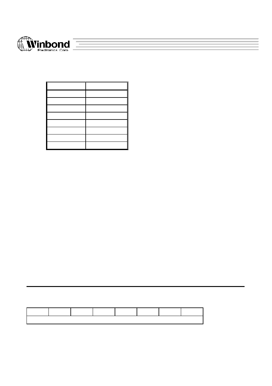
5.2.1 MEMORY CONTROLLER REGISTERS
There are 24 8-bit registers included in the memory (ROM/DRAM) controller. Access to these registers
are through a 8-bit "index" port and a 8-bit data port. The index port address is 0xf0000022 and the data port
address is 0xf0000023. The memory controller supports ROM, Flash, EDO- and Fast-page-mode DRAM.
Table
5.2.1-1 : MEMC Register Map (IO base (BA) : 0xf0000000)
Index
Symbol
Access
Description
0x00
R/W
ROM bank 0 base register [0:7]
0x01
R/W
ROM bank 0 base register [8:15]
0x02
R/W
ROM bank 1 base register [0:7]
0x03
R/W
ROM bank 1 base register [8:15]
0x04
R/W
ROM bank 2 base register [0:7]
0x05
R/W
ROM bank 2 base register [8:15]
0x06
R/W
ROM bank 3 base register [0:7]
0x07
R/W
ROM bank 3 base register [8:15]
0x08
ROMconf0
R/W
ROM Configuration register 0 [0:7]
0x09
ROMconf1
R/W
ROM Configuration register 1 [0:7]
0x0a
ROMconf2
R/W
ROM Configuration register 2 [0:7]
0x0b
ROMconf3
R/W
ROM Configuration register 3 [0:7]
0x20
R/W
RAM bank 0 base register [0:7]
0x21
R/W
RAM bank 0 base register [8:15]
0x22
R/W
RAM bank 1 base register [0:7]
0x23
R/W
RAM bank 1 base register [8:15]
0x24
R/W
RAM bank 2 base register [0:7]
0x25
R/W
RAM bank 2 base register [8:15]
0x26
R/W
RAM bank 3 base register [0:7]
0x27
R/W
RAM bank 3 base register [8:15]
0x28
RAMconf0
R/W
RAM Configuration register 0 [0:7]
0x29
RAMconf1
R/W
RAM Configuration register 1 [0:7]
0x2a
RAMconf2
R/W
RAM Configuration register 2 [0:7]
0x2b
RAMconf3
R/W
RAM Configuration register 3 [0:7]

W90220F
26
Version 0.84
The above information is the exclusive intellectual property of Winbond Electroncs Corp. and shall not be dsiclosed or distributed or reproduced without permission from
Winbond.
ROM Base Address Register ( )
Index : 0x00,0x02,0x04, 0x06
Read/Write
Power-on Default : --
0
1
2
3
4
5
6
7
ROM base address bit 0-7 (most significant bits)
Index : 0x01,0x03,0x05,0x07
Read/Write
Power-on Default : --
0
1
2
3
4
5
6
7
ROM base address bit 8-15
These eight 8-bit registers (boundle to four 16-bit registers) defines the most significant 16 bits
of each ROM banks' base (bottom) address. The "ROM base address" togather with the "ROM
size" (defined in ROMconf0) construct the whole address range of each ROM banks.
These ROM base registers do not contain any initial value after system power-on. All ROM access
will be directed to bank 0 right after system power-on (for ROMconf3[3]=1 at that time). System
programmer shall not set ROMconf3[3] to logic 0 before all ROM base and configuration registers
have been filled with valid data.
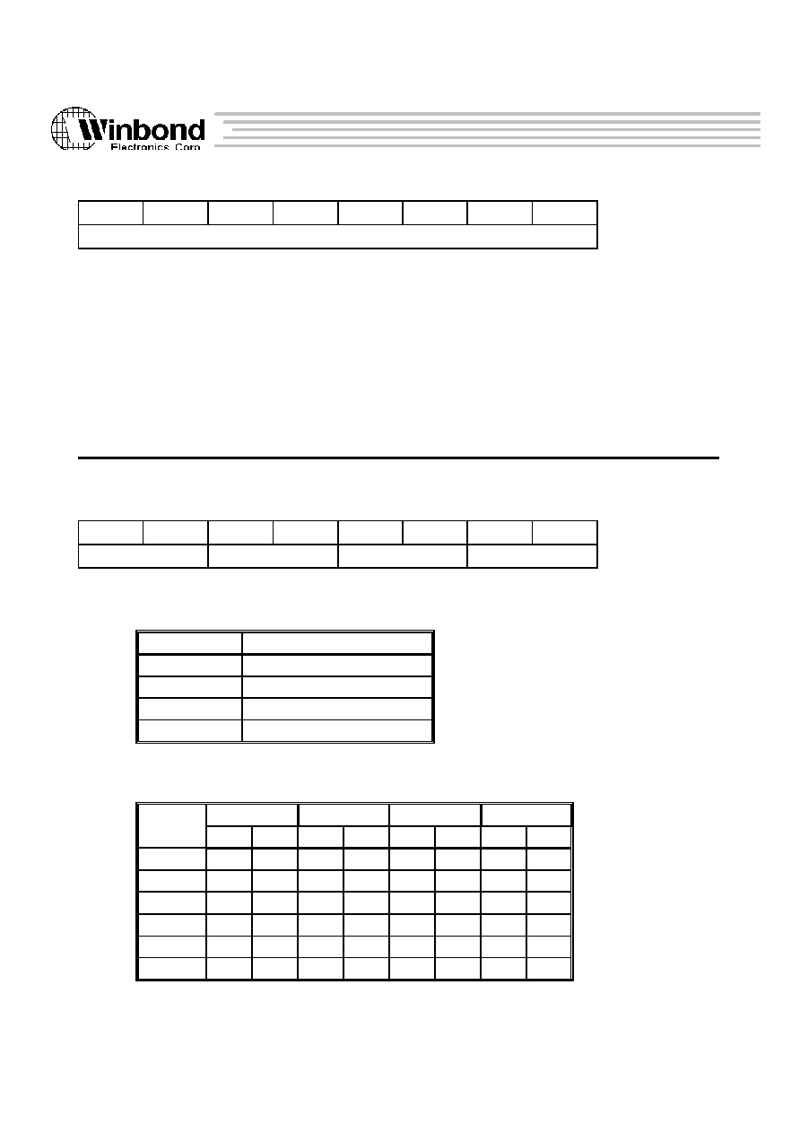
ROM Configuration_0 Register (ROMconf0)
Index : 0x08
Read/Write
Power-on Default : 0x0
0
1
2
3
4
5
6
7
ROMen0
ROM bank_0 size
ROMen1
ROM bank_1 size
Bit 0
Enable ROM bank 0
0 = Disable
1 = Enable
Bits 1-3 Size of ROM bank 0

W90220F
27
Version 0.84
The above information is the exclusive intellectual property of Winbond Electroncs Corp. and shall not be dsiclosed or distributed or reproduced without permission from
Winbond.
ROMconf0[1:3]
ROM size (*Basic unit)
0 0 0
64K
0 0 1
128K
0 1 0
256K
0 1 1
512K
1 0 0
1M
1 0 1
2M
1 1 0
4M
1 1 1
16M
( "*Basic unit" may be "byte", "halfword" or "word" which is
defined in ROMconf2[0:7] )
Bit 4
Enable ROM bank 1
0 = Disable
1 = Enable
Bits 5-7 Size of ROM bank 1
(The definition is the same as ROMconf0[1:3])
ROM Configuration_1 Register (ROMconf1)
Index : 0x09
Read/Write
Power-on Default : 0x0
0
1
2
3
4
5
6
7
ROMen2
ROM bank_2 size
ROMen3
ROM bank_3 size
Bit 0
Enable ROM bank 2
0 = Disable
1 = Enable
Bits 1-3 Size of ROM bank 2
(The definition is the same as ROMconf0[1:3])
Bit 4
Enable ROM bank 3
0 = Disable
1 = Enable

W90220F
28
Version 0.84
The above information is the exclusive intellectual property of Winbond Electroncs Corp. and shall not be dsiclosed or distributed or reproduced without permission from
Winbond.
Bits 5-7 Size of ROM bank 3
(The definition is the same as ROMconf0[1:3])
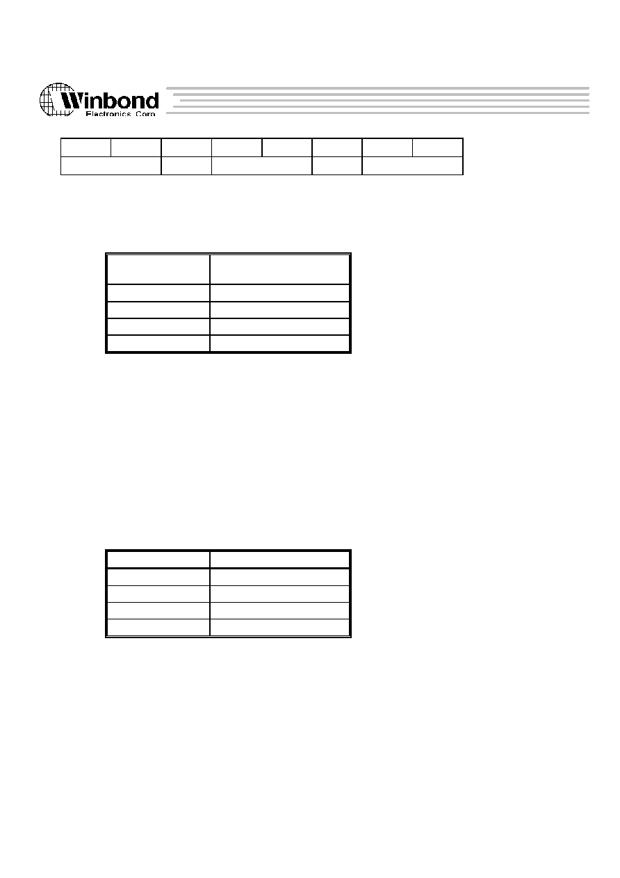
ROM Configuration_2 Register (ROMconf2)
Index : 0x0a
Read/write
Power-on Default : *note
0
1
2
3
4
5
6
7
ROM3DW
ROM2DW
ROM1DW
ROM0DW
Bits 0-1 Data Width of ROM bank 3
ROMconf2[0:1]
Data width
0 0
Byte
0 1
Halfword
1 0
Word
1 1
(reserved)
Bits 2-3 Data Width of ROM bank 2
(The definition is the same as ROMconf2[0:1])
Bits 4-5 Data Width of ROM bank 1
(The definition is the same as ROMconf2[0:1])
Bits 6-7 Data Width of ROM bank 0
(The definition is the same as ROMconf2[0:1])
*note : The default value of this register is determined by MD[30:31]. The states of MD[30:31] will be
copied into ROMconf2[0:1]/[2:3]/4:5]/[6:7] during system power-on (cold) reset.
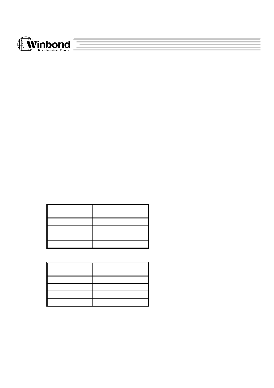
ROM Configuration_3 Register (ROMconf3)
Index : 0x0b
Read/write
Power-on Default : 0b'11011xx
0
1
2
3
4
5
6
7
ROM Read Wait state
BK0only
LA
Reserved
W90220F
29
Version 0.84
The above information is the exclusive intellectual property of Winbond Electroncs Corp. and shall not be dsiclosed or distributed or reproduced without permission from
Winbond.
Bits 0-2 Wait states of ROM Read cycle
ROMconf2[0:2]
Wait States
0 0 0
2
0 0 1
3
0 1 0
4
0 1 1
5
1 0 0
6
1 0 1
7
1 1 0
8
1 1 1
9
Only ROM read cycles have a programmable wait states, while Flash ROM write cycles are
always 9-wait states.
The AC timing of the ROM read/write cycles with different wait states are shown in AC timing
specification.
Bits 3
ROM Bank 0 Only
When this bit is set, all ROM cycles will be directed to bank 0 despite of the programming value
of Base, ROMconf0 and ROMconf1 registers.
Bits 4
Logic Analyzer Mode Enable
This mode is used for chip's testing and debugging. When this bit is set, some of the DMA pins
are used to echo internal 486 bus' control/status signals.
DACK0 echos
ADS#;
IOR
echos
BLAST#;
DACK1 echos
MIO#
IOW
echos
BRDY#
CS0
echos
DC#;
TC0
echos
RDY#;
CS1
echos
WR#;
TC1
echos
HLDA
RAM Base Address Register ( )
Index : 0x20,0x22,0x24, 0x26
Read/Write
Power-on Default : --
0
1
2
3
4
5
6
7
RAM base address bit 0-7 (most significant bits)
Index : 0x21,0x23,0x25,0x27
Read/Write
Power-on Default : --
W90220F
30
Version 0.84
The above information is the exclusive intellectual property of Winbond Electroncs Corp. and shall not be dsiclosed or distributed or reproduced without permission from
Winbond.
0
1
2
3
4
5
6
7
RAM base address bit 8-15
These eight 8-bit registers (boundle to four 16-bit registers) defines the most significant 16 bits
of each RAM banks' base (bottom) address. The "RAM base address" togather with the "RAM
size" (defined in ROMconf0) construct the whole address range of each RAM banks.
The base address of all four DRAM banks have no default value after power-on reset. It is software's
responsibility to well program these registers before access system DRAM.
RAM Configuration_0 Register (RAMconf0)
Index : 0x28
Read/Write
Power-on Default : 0x0
0
1
2
3
4
5
6
7
RAMTP3
RAMTP2
RAMTP1
RAMTP0
Bits 0-1 DRAM Bank 3's RAM type & Bank-size
RAMconf0[0:1]
RAM type & Bank size (x32)
0 0
256K
0 1
1M
1 0
4M
1 1
16M
The following table defines how CPU address bus map to DRAM address :
256K
1M
4M
16M
ROW
COL
ROW
COL
ROW
COL
ROW
COL
MA11
*(A6)
*(A18)
*(A6)
*(A18)
*(A6)
*(A18)
A6
A18
MA10
*(A8)
*(A19)
*(A8)
*(A19)
A8
A19
A8
A19
MA9
*(A10)
*(A20)
A10
A20
A10
A20
A10
A20
MA8
A20
A29
A11
A29
A11
A29
A11
A29
MA7
A19
A28
A19
A28
A9
A28
A9
A28
MA6
A18
A27
A18
A27
A18
A27
A7
A27

W90220F
31
Version 0.84
The above information is the exclusive intellectual property of Winbond Electroncs Corp. and shall not be dsiclosed or distributed or reproduced without permission from
Winbond.
MA5
A17
A26
A17
A26
A17
A26
A17
A26
MA4
A16
A25
A16
A25
A16
A25
A16
A25
MA3
A15
A24
A15
A24
A15
A24
A15
A24
MA2
A14
A23
A14
A23
A14
A23
A14
A23
MA1
A13
A22
A13
A22
A13
A22
A13
A22
MA0
A12
A21
A12
A21
A12
A21
A12
A21
Bank Selector
Bank Selector
Bank Selector
Bank Selector
2 Banks
A11
A9
A7
A5
4 Banks
A10, A11
A8, A9
A6, A7
A4, A5
Note * : Don't care pins (only for testing issue).
** : A0 is MSB and A31is LSB.
Bits 2-3 DRAM Bank 2's RAM type & Bank-size
(The definition is the same as RAMconf0[0:1])
Bits 4-5 DRAM Bank 1's RAM type & Bank-size
(The definition is the same as RAMconf0[0:1])
Bits 6-7 DRAM Bank 0's RAM type & Bank-size
(The definition is the same as RAMconf0[0:1])
RAM Configuration_1 Register (RAMconf1)
Index : 0x29
Read/Write
Power-on Default : 0x0
0
1
2
3
4
5
6
7
PAREN
RAMen3
RAMen2
RAMen1
RAMen0
DIS384K
FW
FR
Bit 0
Enable parity-check of memory data bus
0 = Disable parity check
1 = Enable parity check
Bit 1
DRAM bank_3 enable
0 = Disable
1 = Enable
Bit 2
DRAM bank_2 enable
W90220F
32
Version 0.84
The above information is the exclusive intellectual property of Winbond Electroncs Corp. and shall not be dsiclosed or distributed or reproduced without permission from
Winbond.
0 = Disable
1 = Enable
Bit 3
DRAM bank_1 enable
0 = Disable
1 = Enable
Bit 4
DRAM bank_0 enable
0 = Disable
1 = Enable
Bit 5
Swap out 0xA0000 ~ 0xFFFFF
When this bit is set to a logic 1, address space 0xA0000 ~ 0xFFFFF will not be recognized as
"system" DRAM space.
Bit 6
Fast Write Enable (FW)
"FW" together with RAMconf2[2:3] ("CASPC, CASWR") determine CAS# precharge- and
active-time during "DRAM write" cycles.
(Table 5.2.1-2 CAS# precharge-time during "write cycle")
FW, CASPC
CAS# precharge-time
(SYSCLK)
1 0
0.5
1 1
0.5
0 0
1
0 1
2
(Table 5.2.1-3. CAS# active-time during "write cycle")
FW, CASWR
CAS# active-time
(SYSCLK)
1 0
0.5
1 1
1.5
0 0
1
0 1
2
Bit 7
Fast Read Enable (FR)
"FR" together with RAMconf2[2] ("CASPC") and RAMconf3[6:7] ("CASRD[0:1]") deter-
mine CAS# precharge- and active-time during "DRAM read" cycles.

W90220F
33
Version 0.84
The above information is the exclusive intellectual property of Winbond Electroncs Corp. and shall not be dsiclosed or distributed or reproduced without permission from
Winbond.
(Table 5.2.1-4. CAS# precharge-time during "read cycle")
FR, CASPC
CAS# precharge-time
(SYSCLK)
1 0
0.5
1 1
0.5
0 0
1
0 1
2
(Table 5.2.1-5. CAS# active-time during "read cycle")
FW, CASRD[0:1]
CAS# active-time
(SYSCLK)
1 0 0
0.5
1 0 1
1.5
1 1 0
2.5
1 1 1
3.5
0 0 0
1
0 0 1
2
0 1 0
3
0 1 1
4
RAM Configuration_2 Register (RAMconf2)
Index : 0x2a
Read/Write
Power-on Default : 0x15
0
1
2
3
4
5
6
7
RASPC[0:1]
CASPC
CASWR
R2CRD[0:1]
R2CWR[0:1]
Bits 0-1 RAS# precharge time (RASPC[0:1])
"RASPC[0:1]" determine RAS# precharge-time during every "DRAM " cycles.
(Table 5.2.1-6. RAS# precharge-time during "DRAM cycle")
RASPC[0:1]
RAS# precharge-time
(SYSCLK)
0 0
2
0 1
3
1 0
4
1 1
5

W90220F
34
Version 0.84
The above information is the exclusive intellectual property of Winbond Electroncs Corp. and shall not be dsiclosed or distributed or reproduced without permission from
Winbond.
Bits 2
CAS# precharge time (CASPC)
This bit together with RAMconf1[6:7] ("FW, FR") determine CAS# precharge-time during
"DRAM write or read" cycles respectively. Please refer Table 5.2.1-2 and Table 5.2.1-4 to get detail
information.
Bits 3
CAS# active time during DRAM-write (CASWR)
This bit together with RAMconf1[6] ("FW ") determine CAS# active-time during "DRAM
write" cycles. Please refer Table 5.2.1-3 to get detail information.
Bits 4-5 RAS# to CAS# delay time during DRAM-read cycles (R2CRD[0:1])
"R2CRD[0:1]" determine RAS# to CAS# delay during "DRAM-read" cycles if bank or
page is changing at that time.
(Table 5.2.1-7 RAS# to CAS# delay during "read cycle")
R2CRD[0:1]
RAS# to CAS# delay
(SYSCLK)
0 0
1
0 1
2
1 0
3
1 1
4
Bits 6-7 RAS# to CAS# delay time during DRAM-write cycles (R2CWR[0:1])
"R2CWR[0:1]" determine RAS# to CAS# delay during "DRAM-write" cycles if bank or
page is changing at that time.
(Table 5.2.1-8. RAS# to CAS# delay during "write cycle")
R2CWR[0:1]
RAS# to CAS# delay
(SYSCLK)
0 0
1
0 1
2
1 0
3
1 1
4
RAM Configuration_3 Register (RAMconf3)
Index : 0x2b
Read/Write
Power-on Default : 0x09
W90220F
35
Version 0.84
The above information is the exclusive intellectual property of Winbond Electroncs Corp. and shall not be dsiclosed or distributed or reproduced without permission from
Winbond.
0
1
2
3
4
5
6
7
REFRAT[0:1]
CD2RD
RA2CD[0:1]
CA2RA
CASRD[0:1]
Bits 0-1 Refresh Rate (REFRAT[0:1])
REFRAT[0:1] determine the frequence of DRAM refresh cycles.
(Table 5.2.1-9 The frequence of DRAM refresh cycles)
REFRAT[0:1]
Frequence of refresh cycle
(us)
0 0
15
0 1
60
1 0
240
1 1
960
Bit 2
CAS# deassertion to RAS# deassertion (CD2RD)
0 = The delay time for CAS# deassertion to RAS# deassertion is 1 SYSCLK
for CAS-before-RAS refresh cycle.
1 = The delay time for CAS# deassertion to RAS# deassertion is 2 SYSCLK
for CAS-before-RAS refresh cycle.
Bits 3-4 RAS# assertion to CAS# deassertion (RA2CD[0:1])
These two bits determine the duration between RAS# assertion to CAS# deassertion for CAS-
before-RAS refresh cycle.
(Table 5.2.1-10 Delay time from RAS# assertion to CAS# deassertion)
RA2CD[0:1]
Delay (SYSCLK)
0 0
1
0 1
2
1 0
3
1 1
4
Bit 5
CAS# assertion to RAS# assertion (CA2RA)
0 = The delay time for CAS# assertion to RAS# assertion is 1 SYSCLK
for CAS-before-RAS refresh cycle.
1 = The delay time for CAS# assertion to RAS# assertion is 2 SYSCLK
for CAS-before-RAS refresh cycle.
Bits 6-7 CAS# active time during DRAM-read (CASRD[0:1])

W90220F
36
Version 0.84
The above information is the exclusive intellectual property of Winbond Electroncs Corp. and shall not be dsiclosed or distributed or reproduced without permission from
Winbond.
These two bits together with RAMconf1[7] ("FR ") determine CAS# active-time during
"DRAM read" cycles. Please refer Table 5.2.1-5 to get detail information.
5.2.2 DMA REGISTERS
There are twelve registers included in two channels Direct Memory Access (DMA) controller. The IO address map
is allocated from 0xf0000200 to 0xf000022c.
Table 5.2.2-1 : DMA Register Map (IO base (BA) : 0xf0000000)
Port Addr.
Symbol
Access
Description
BA + 0x200
SAR0
R/W
Channel 0 Source Address Register
BA + 0x204
TAR0
R/W
Channel 0 Target Address Register
BA + 0x208
LETH0
R/W
Channel 0 Length Register
BA + 0x20c
MOD0
R/W
Channel 0 Mode Control Register
BA + 0x210
SAR1
R/W
Channel 1 Source Address Register
BA + 0x214
TAR1
R/W
Channel 1 Target Address Register
BA + 0x218
LETH1
R/W
Channel 1 Length Register
BA+ 0x21c
MOD1
R/W
Channel 1 Mode Control Register
BA + 0x220
DBA0
R/W
DMA IO Device 0 Bass Address
BA + 0x224
DBA1
R/W
DMA IO Device 1 Base Address
BA + 0x228
LCAR0
R
Channel 0 Length Counter
BA + 0x22c
LCAR1
R
Channel 1 Length Counter
Source Addrsee Register (SAR0 and SAR1)
Port address : 0xf0000200
Read/Write
Power-on Default : 0x00000000
Port address : 0xf0000210
Read/Write
Power-on Default : 0x00000000

W90220F
37
Version 0.84
The above information is the exclusive intellectual property of Winbond Electroncs Corp. and shall not be dsiclosed or distributed or reproduced without permission from
Winbond.
0
1
2
3
4
5
6
7
Source Address Register byte 0
8
9
10
11
12
13
14
15
Source Address Register byte 1
16
17
18
19
20
21
22
23
Source Address Register byte 2
24
24
26
27
28
29
30
31
Source Address Register byte 3
Bit 0-31 Source address register(SAR)
Define DMA transfer source address. In memory to memory mode, the source address should
be set in word boundary.
Target Address Register (TAR0 and TAR1)
Port address : 0xf0000204
Read/Write
Power-on Default : 0x00000000
Port address : 0xf0000214
Read/Write
Power-on Default : 0x00000000
0
1
2
3
4
5
6
7
Target Address Register byte 0
8
9
10
11
12
13
14
15
Target Address Register byte 1
16
17
18
19
20
21
22
23
Target Address Register byte 2
24
24
26
27
28
29
30
31
Target Address Register byte 3
Bit 0-31 DMA target address register(TAR)
Define target address. In memory to memory mode, the target address should be set in word

W90220F
38
Version 0.84
The above information is the exclusive intellectual property of Winbond Electroncs Corp. and shall not be dsiclosed or distributed or reproduced without permission from
Winbond.
boundary.
Length Register (LETH0 and LETH1)
Port address : 0xf0000208
Read/write
Power-on Default : 0x00000000
Port address : 0xf0000218
Read/write
Power-on Default : 0x00000000
0
1
2
3
4
5
6
7
Reserved
8
9
10
11
12
12
14
15
Reserved
LEN0
16
17
18
19
20
21
22
23
LEN1-8
24
24
26
27
28
29
30
31
LEN9-16
Bit 0-14 Reserved
Bit 15-31 Transfer Length
(LEN)
LEN 0-16 indicate DMA transfer length with max 128k-byte transferring. In memory to memory
tranfser mode, the length must in word boundary, because of vounting by word in length counter.
Mode Control Register (MOD0 and MOD1)
Port address : 0xf000020c
Read/Write
Power-on Default : 0x0000000f
Port address : 0xf000020c
Read/Write
Power-on Default : 0x00000000
0
1
2
3
4
5
6
7
DMAen
Reserved
TCIen
ECPen
TC
M2M
DEM
IOtype0

W90220F
39
Version 0.84
The above information is the exclusive intellectual property of Winbond Electroncs Corp. and shall not be dsiclosed or distributed or reproduced without permission from
Winbond.
8
9
10
11
12
13
14
15
IOtype1
TRtype
IOrec
16
17
18
19
20
21
22
23
Wstate
FIX
Reserved
Tout0
(MOD0)
Wsate
DACK0L DACK1L
CS0L
(MOD1)
24
25
26
27
28
29
30
31
Tout1-8
(MOD0)
CS1L
DACK1A
TO0
TO1
Reserved
(MOD1)
Bit 0
DMA enable(DMAen)
1 = DMA transfer enable.
0 = DMA transfer disable
Bit 1
Reserved
Set to 0
Bit 2
Terninal count interrupt enable(TCIen)
1 = enable terminal count interrupt
Once this bit is set, and TC is asserted, the DMAC will generate external interrupt to host.
Bit 3
Enable ECP as DMA device(ECPen)
1 = ECP is set as DMA device
Bit 4
Terminal count flag(TC)
1 = indicate the length counter reaches 0, and theTC asserted
Bit 5
Memory to memory transfer(M2M)
1 = DMA is set to memory to memory transfer
0 = DMA memory to memory transfer is disable
Bit 6
Demand mode or block mode select(DEM)
1 = DMA transfer between memory and IO is demand mode
0 = DMA transfer between memory and IO is block mode

W90220F
40
Version 0.84
The above information is the exclusive intellectual property of Winbond Electroncs Corp. and shall not be dsiclosed or distributed or reproduced without permission from
Winbond.
This bit is valid only in the transfer between memory and IO.
Bit 7-8 DMA IO device type(IOtype)
00 = 8-bit type, length counter(LENC) counts by byte
01 = 16-bit type, length counter counts by half word
10 = 32-bit type, length counter countes by word
11 = undefined
Only 8-bit external IO device is supported.
Bit 9-10 DMA transfer type(TRtype)
00 = memory to memory transfer
01 = memory to IO transfer
1x = IO to memory transfer
Bit 11-15
DMA IO read/write command recovery time(IOrec)
This field define the recovery cycle between two read/write command.
Bit 16-20
DMA IO read/write command wait state(Wstate)
This field define the IO read/write command wait state.
In MOD0:
Bit21
DMA transfer fix mode(FIX)
1 = Set DMA transfer as rotate mode. In rotate mode, the DMA controller acknowledge channel 1
request right after channel 0 being served. The channel 1 and channel 0 are served by turns.
0 = DMA is set in fix mode. Channel 0 is the most privilege. The channel 1 will not get the service
token, unless channel 0 release the request.
Bit22
Reserved
This bit should be set to 0.
Bit23-31 Ready timeout counter(Tout)
Set IO device assert NOT ready timeout cycle count. When IO read/write command is issued, and if
the IO device inserts wait state by asserting IORDY, the ready timeout counter starts to count. If the
counter reach the Tout before read/write command is completed, the timeout flag TO0 or TO1 is to
be set.

W90220F
41
Version 0.84
The above information is the exclusive intellectual property of Winbond Electroncs Corp. and shall not be dsiclosed or distributed or reproduced without permission from
Winbond.
In MOD1:
Bit 21
Set DACK0 low active(DACK0L)
1 = set DMA acknowledge signal DACK0 to low active
0 = set DMA acknowledge signal DACK0 to high active
Bit 22 Set DACK1 low active(DACK1L)
1 = set DMA acknowledge signal DACK1 to low active
0 = set DMA acknowledge signal DACK1 to high active
Bit 23
Set CS0 low active(CS0L)
1 = Set IO device chip select CS0 to low active
0 = Set IO device chip select CS0 to high active
Bit 24
Set CS1 low active(CS1L)
1 = Set IO device chip select CS1 to low active
0 = Set IO device chip select CS1 to high active
Bit 25 DACK1 active
1 = indicate DMA channel 1 acknoewledge DACK1 is active
Bit 26
Channel 0 time out(TO0)
1 = indicate channel 0 IORDY signal timeout
This bit is read ONLY.
Bit 27
Channel 0 time out(TO1)
1 = indicate channel 1 IORDY signal timeout
This bit is read ONLY.
Bit28-31
Reserved
DMA IO Device Bass Address (DBA0 and DBA1)
Port address : 0xf0000220
Read/write
Power-on Default : 0xfffff000
Port address : 0xf0000224
Read/write
Power-on Default : 0xfffff000

W90220F
42
Version 0.84
The above information is the exclusive intellectual property of Winbond Electroncs Corp. and shall not be dsiclosed or distributed or reproduced without permission from
Winbond.
0
1
2
3
4
5
6
7
DBA0-7
8
9
10
11
12
12
14
15
DBA8-15
16
17
18
19
20
21
22
23
DBA16-19
Reserved
24
24
26
27
28
29
30
31
Reserved
Bit0-19 DMA IO device base address(DBA)
Define DMA device IO base. The base address should not conflict to internal mega cell base, and the
bit0-3 should be always set to 0
.
Bit 20-31 Reserved
Length Counter Register (LCAR0 and LCAR1)
Port address : 0xf0000228
Read only
Power-on Default : ---
Port address : 0xf000022c
Read only
Power-on Default : ---
0
1
2
3
4
5
6
7
Reserved
8
9
10
11
12
12
14
15
Reserved
LENC0
16
17
18
19
20
21
22
23
LENC1-8

W90220F
43
Version 0.84
The above information is the exclusive intellectual property of Winbond Electroncs Corp. and shall not be dsiclosed or distributed or reproduced without permission from
Winbond.
24
24
26
27
28
29
30
31
LENC9-16
Bit 0-14 Reserved
Bit 15-31 Length counter indicates the remainder to be transfer. DMA transfered number = Length Register -
LENC. TC is asserted by Length counter reaching 0. Reading Length Counter may not get the valid
value if the channel is active, for the length may be in transition.
5.2.3 PCI BRIDGE INTERFACE REGISTERS
There are four 32 bits registers included in the PCI Bridge Interface controller. The IO address map is allocated
from 0xf0000250 to 0xf000025c.
Table 5.2.3-1 : PCI Bridge Register Map (IO base (BA) : 0xf0000000)
Port Addr.
Symbol
Access
Description
BA + 0x250
REG0
R/W
Master 0 Latency Register
BA + 0x254
REG1
R/W
Master 1 Latency Register
BA + 0x258
REG2
R/W
Master 2 Latency Register
BA + 0x25c
REG3
R/W
Master 3 Latency Register
Master 0 Latency Register (REG0)
Port address : 0xf0000250
Read/Write
Power-on Default : 0x000003ff
0
1
2
3
4
5
6
7

W90220F
44
Version 0.84
The above information is the exclusive intellectual property of Winbond Electroncs Corp. and shall not be dsiclosed or distributed or reproduced without permission from
Winbond.
Reserved
8
9
10
11
12
13
14
15
Reserved
16
17
18
19
20
21
22
23
PERRen
SERRen
Reserved
REQ0_reg[0:2]
24
25
26
27
28
29
30
31
REQ0_reg[3:10]
Bits 0-15 Reserved
Bit 16 Parity Error Enable
0 = disable
1 = enable
Bit 17 System Error Enable
0 = disable
1 = enable
Bits 18-20 Reserved
Bits 21-31 Number of PCICLK count for Master Latency Adjustment
Latency Time = REQ0_reg[0:11] / PCICLK
Master 1 Latency Register (REG1)
Port address : 0xf0000254
Read/Write
Power-on Default : 0x000003ff
0
1
2
3
4
5
6
7
Reserved
W90220F
45
Version 0.84
The above information is the exclusive intellectual property of Winbond Electroncs Corp. and shall not be dsiclosed or distributed or reproduced without permission from
Winbond.
8
9
10
11
12
13
14
15
Reserved
16
17
18
19
20
21
22
23
Reserved
CPURST
FIX
REQ1_reg[0:2]
24
25
26
27
28
29
30
31
REQ1_reg[3:10]
Bits 0-18 Reserved
Bit 19 CPU Reset Signal
0 = disable
1 = generate CPU Reset Signal
Bit 20 Request Priority Select
0 = Rotate Priority
1 = Fix priority
Bits 21-31 Number of PCICLK count for Master Latency Adjustment
Latency Time = REQ1_reg[0:11] / PCICLK
Master 2 Latency Register (REG2)
Port address : 0xf0000258
Read/Write
Power-on Default : 0x000003ff
0
1
2
3
4
5
6
7
Reserved

W90220F
46
Version 0.84
The above information is the exclusive intellectual property of Winbond Electroncs Corp. and shall not be dsiclosed or distributed or reproduced without permission from
Winbond.
8
9
10
11
12
13
14
15
Reserved
16
17
18
19
20
21
22
23
Reserved
REQ2_reg[0:2]
24
25
26
27
28
29
30
31
REQ2_reg[3:10]
Bits 0-20 Reserved
Bits 21-31 Number of PCICLK count for Master Latency Adjustment
Latency Time = REQ2_reg[0:11] / PCICLK
Master 3 Latency Register (REG3)
Port address : 0xf000025c
Read/Write
Power-on Default : 0x000003ff
0
1
2
3
4
5
6
7
Reserved
8
9
10
11
12
13
14
15
Reserved
16
17
18
19
20
21
22
23
Reserved
REQ3_reg[0:2]

W90220F
47
Version 0.84
The above information is the exclusive intellectual property of Winbond Electroncs Corp. and shall not be dsiclosed or distributed or reproduced without permission from
Winbond.
24
25
26
27
28
29
30
31
REQ3_reg[3:10]
Bits 0-20 Reserved
Bits 21-31 Number of PCICLK count for Master Latency Adjustment
Latency Time = REQ3_reg[0:11] / PCICLK
5.2.4 PARALLEL PORT INTERFACE REGISTERS
There are eleven registers included in the Parallel Port Interface (PPI) controller. The IO address map is allocated
from 0xf0000370 to 0xf000037f.
Table 5.2.4-1 : PPI Register Map (IO base (BA) : 0xf0000000)
Port Addr.
Symbol
Access
Description
BA + 0x378
DL
R/W
Data Line Register
BA + 0x379
DSR
R
Device Status Register
BA + 0x37a
DCR
R/W
Device Control Register
BA + 0x37b
FSR
R
FIFO Status Register
BA + 0x37c
FCR
R/W
FIFO Control Register
BA + 0x37d
IER
R/W
Interrupt Enable Register
BA + 0x37e
IIR
R
Interrupt Identification Register
BA+ 0x37f
DR
R
Data Register
BA + 0x370
Dfifo
R/W
Data FIFO
BA + 0x374
CMD
R/W
Command Register
BA + 0x375
TOR
R/W
Time Out Register
BA + 0x376 ~
BA + 0x377
-
-
Reserve for PPI future extension

W90220F
48
Version 0.84
The above information is the exclusive intellectual property of Winbond Electroncs Corp. and shall not be dsiclosed or distributed or reproduced without permission from
Winbond.
Data Line Register (DL)
Port address : 0xf0000378
Read/Write
Power-on Default : --
0
1
2
3
4
5
6
7
8-bit Data Lines status
Bits 0-7 Data Lines status
This is the standard parallel port data register. Writing to this register will drive data to the
parallel port data lines. Reads to this register return the value on the data lines.
Device Status Register (DSR)
Port address : 0xf0000379
Read only
Power-on Default : ---
0
1
2
3
4
5
6
7
BUSY#
nACK
PE
SEL
nFAULT
EMPTY
FULL
CMDtrue
Bits 0
Inverted version of Parallel Port Interface "BUSY" signal
Bit 1
Version of Parallel Port Interface "nACK" signal
Bit 2
Version of Parallel Port Interface "PError" signal
Bit 3
Version of Parallel Port Interface "Select" signal
Bit 4
Version of Parallel Port Interface "nFault" signal
Bit 5
Echo device data FIFO "empty" status
0 = device data FIFO is not empty
1 = device data FIFO is empty
Bit 6
Echo device data FIFO "full" status
0 = device data FIFO is not full
1 = device data FIFO is full

W90220F
49
Version 0.84
The above information is the exclusive intellectual property of Winbond Electroncs Corp. and shall not be dsiclosed or distributed or reproduced without permission from
Winbond.
Bit 7
"Command" pended
0 = Command Register (CMD) contains no command code
1 = A command code is in CMD not been transfered yet
This read-only register reflects the inputs on the Parallel Port Interface and some of device data
FIFO and Command Register status.
Device Control Register (DCR)
Port address : 0xf000037a
Read/write
Power-on Default : 0x0
0
1
2
3
4
5
6
7
Reserved
DOE
nAck_Ien nSELIN#
nINIT
nAUFD#
nSTB#
Bit 2
Data bus output enable
0 = Data bus is drived by PPI for forward transfering
1 = Data bus is drived by peripheral device for reverse transfering
This bit has no effects during "peripheral emulation mode", "standard mode",
"fast standard mode" and "PS2 mode".
Bit 3
nACK interrupt enable
0 = Data bus is drived by PPI for forward transfering
1 = Data bus is drived by peripheral device for reverse transfering
When this bit is set. A low-to-high transition will generate a interrupt request to CPU core.
Bit 4
Complement version of Parallel Port Interface "nSelectIn" signal
Bit 5
Version of Parallel Port Interface "nInit" signal
Bit 6
Complement version of Parallel Port Interface "nAutoFd" signal
Bit 7
Complement version of Parallel Port Interface "nStrobe" signal
This register directly controls several output signals as well as enabling some functions. The power-
on default "0x0" makes {nSelectIn, nInit, nAutoFd, nStrobe} in {high, low, high, high} state, and

W90220F
50
Version 0.84
The above information is the exclusive intellectual property of Winbond Electroncs Corp. and shall not be dsiclosed or distributed or reproduced without permission from
Winbond.
8-bit data bus in output enable mode which are suit for "standard mode" transfering.
FIFO Status Register (FSR)
Port address : 0xf000037b
Read only
Power-on Default : ---
0
1
2
3
4
5
6
7
Dfifo valid bytes
DA
SA
OV
Bits 0-4 Valid bytes in device data FIFO (Dfifo)
During forward transfering, these bits indicate that how many bytes in 16-byte Dfifo still
not be transfered yet. While during reverse transfering, these bits shows the number of
data bytes which received from parallel port interface and not be read by CPU core.
Bit 5
Dfifo data available
0 = Dfifo contains data bytes less than one "PWord"
1 = Dfifo contains at least one "PWord" of valid data.
Bit 6
Dfifo space available
0 = Dfifo contains empty locations less than one "PWord"
1 = Dfifo contains at least one "PWord" of empty locations.
Bit 7
Dfifo over/under run
0 = Dfifo is not yet over- or under-run
1 = Dfifo is already over- or under-run
Once this bit is set, it will keep on set state until Dfifo or the PPI is reset.
FIFO Control Register (FCR)
Port address : 0xf000037c
Read/Write
Power-on Default : 0x0
0
1
2
3
4
5
6
7
DMAen
FRST
DRST
PWord
MOD
RDTH

W90220F
51
Version 0.84
The above information is the exclusive intellectual property of Winbond Electroncs Corp. and shall not be dsiclosed or distributed or reproduced without permission from
Winbond.
Bits 0
DMA mode enable
A low-to-high transition of this bit will make PPI issue a DREQ to DMA controller.
On receiving the corresponding DACK, PPI deasserts the DREQ.
This bit will be cleared by DMA terminal-count (TC) asserting or by a CPU write
cycle with data-in[0] = 0.
Bit 1
Reset Dfifo
Writing a logical one to this bit will assert "Dfifo Reset" for one EXTCLK cycle.
This bit will return to deasserted state automatically after "Dfifo Reset" is issued.
Bit 2
Reset Device
Writing a logical one to this bit will assert "Device Reset" for one EXTCLK cycle.
This bit will return to deasserted state automatically after "Device Reset" is issued.
Bit 3
PWord size
0 = PWord is 8 bits (1 byte)
1 = PWord is 32 bits (4 bytes)
"PWord" defines the basic unit of Dfifo access during CPU cycle.
Bit 4-5 Device mode select
IER[1] and FCR[4:5] are used to choose device operation mode.
{IER[1], FCR[4:5]}
Device Operation Mode
1 x 0
Test Mode
1 x 1
Peripheral Emulation Mode
0 0 0
Standard Mode
0 0 1
PS2 Mode
0 1 0
Fast Standard Mode
0 1 1
ECP Mode
Bit 6-7 Dfifo Read Threshold
These two bits define the threshold level for triggering data-available interrupt (Irpt_RDA)
of Dfifo during reverse transfering.
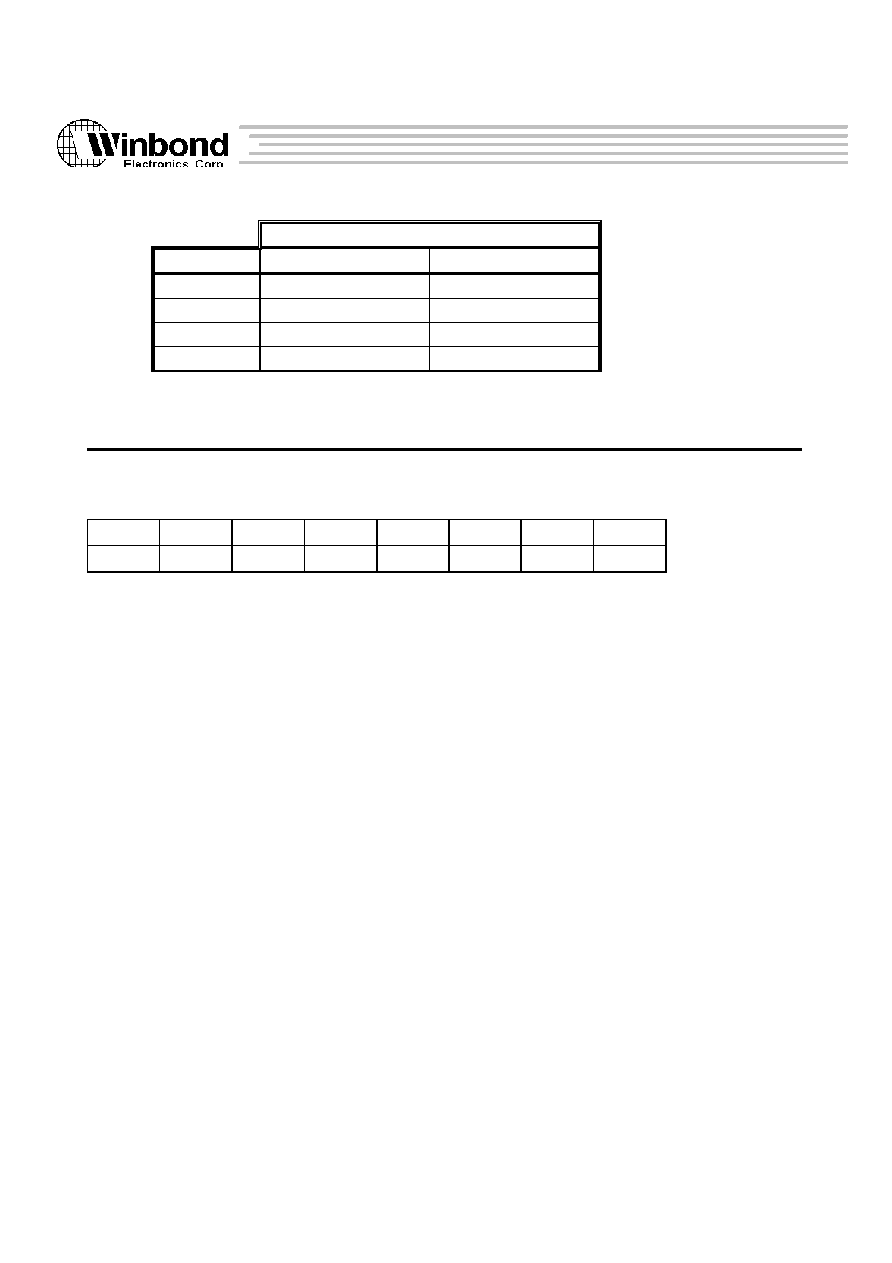
W90220F
52
Version 0.84
The above information is the exclusive intellectual property of Winbond Electroncs Corp. and shall not be dsiclosed or distributed or reproduced without permission from
Winbond.
Read Threshold level
FCR[6:7]
PWord = 1 byte
PWord = 4 bytes
0 0
16 bytes
16 bytes
0 1
12 bytes
12 bytes
1 0
8 bytes
8 bytes
1 1
1 byte
4 bytes
Interrupt Enable Register (IER)
Port address : 0xf000037d
Read/Write
Power-on Default : 0x0
0
1
2
3
4
5
6
7
Reserved
PEMU
Tout_Ien
TC_Ien
Temp_Ien
Rda_Ien
nFault_Ien
LOOP
Bits 1
Peripheral Emulation Mode enable
0 = Device is not operating in "Peripheral Emulation Mode" or "Test Mode"
1 = Set device to "Peripheral Emulation Mode" or "Test Mode"
This bit along with FCR[4:5] are used to choose device operation mode.
Bit 2
Time-Out Interrupt (Irpt_TOUT) enable
0 = Mask Irpt_TOUT
1 = Enable Irpt_TOUT
Bit 3
DMA Terminal-Count Interrupt (Irpt_TC) enable
0 = Mask Irpt_TC
1 = Enable Irpt_TC
Bit 4
Dfifo Empty Interrupt (Irpt_TEMP) enable
0 = Mask Irpt_TEMP
1 = Enable Irpt_TEMP
Bit 5
Dfifo Read Threshold Interrupt (Irpt_RDA) enable
0 = Mask Irpt_RDA
1 = Enable Irpt_RDA

W90220F
53
Version 0.84
The above information is the exclusive intellectual property of Winbond Electroncs Corp. and shall not be dsiclosed or distributed or reproduced without permission from
Winbond.
Bit 6
"nFault" Interrupt (Irpt_nFault) enable
0 = Mask Irpt_nFault
1 = Enable Irpt_nFault
Bit 7
Loop back enable
0 = Loop-back disable
1 = Loop-back enable
During Loop-Back mode, {nStrobe, nAutoFd, nInit, nSelectIn} will be fed to
{nAck, Busy, PError, nFault} internally. This mode is used only for test issue.
Interrupt Identification Register (IIR)
Port address : 0xf000037e
Read only
Power-on Default : ---
0
1
2
3
4
5
6
7
Reserved
Irpt_Tout
Irpt_TC
Irpt_Temp Irpt_RDA Irpt_nFaul
t
Irpt_nAck
Bits 2
Time-Out Interrupt flag
"Set" situation
: If IER[2] is set, and "Time out" is occured during parallel port
transfering.
"Reset" situation : Reset device, or CPU reads Time-Out Register (TOR) or Dfifo
being accessed either by CPU or parallel port interface transfering.
Bits 3
DMA Terminal Count Interrupt flag
"Set" situation
: If IER[3] is set, and TC is asserted by DMA controller once DMA
transfer is done.
"Reset" situation : TC is deasserted by DMA controller.
Bits 4
Dfifo Empty Interrupt flag
"Set" situation
: If IER[4] is set, and Dfifo is empty during "forward transfering".
"Reset" situation : CPU write new data into Dfifo.
Bits 5
Dfifo Read Threshold Interrupt flag
"Set" situation
: If IER[5] is set, and data bytes received by Dfifo are exceeded the
threshold level (defined in FCR[4:5] ) during "reverse transfering".

W90220F
54
Version 0.84
The above information is the exclusive intellectual property of Winbond Electroncs Corp. and shall not be dsiclosed or distributed or reproduced without permission from
Winbond.
"Reset" situation : CPU read Dfifo such that data bytes in Dfifo are below the thresh-
hold level.
Bits 6
"nFault" Interrupt flag
"Set" situation
: If IER[6] is set, and a high-to-low transition is on "nFault" pin.
"Reset" situation : CPU read Device Status Register (DSR).
Bits 7
"nAck" Interrupt flag
"Set" situation
: If DCR[3] is set, and a low-to-high transition is on "nAck" pin.
"Reset" situation : CPU read Device Status Register (DSR).
Data Register (DR)
Port address : 0xf000037f
Read only
Power-on Default : ---
0
1
2
3
4
5
6
7
8-bit Data of latched Lines status
Bits 0-7 Latched Line status
The status of data lines of PPI will be latched into this register if a high-to-low
transition is happened on "nAck" pin.
This register is added to support "Peripheral Emulation Mode" operation.
Device Data FIFO (Dfifo)
Port address : 0xf0000370
Read/write
Power-on Default : ---
0
1
2
3
4
5
6
7
Dfifo MSB byte
8
9
10
11
12
13
14
15

W90220F
55
Version 0.84
The above information is the exclusive intellectual property of Winbond Electroncs Corp. and shall not be dsiclosed or distributed or reproduced without permission from
Winbond.
16
17
18
19
20
21
22
23
24
25
26
27
28
29
30
31
Dfifo LSB byte
The device build-in a 16-byte data fifo to accelerate the transfer rate when using "Fast Standard
Mode" or "ECP mode".
The Dfifo may be 1-byte or 4-byte accessed by CPU using "PWord" basis.
Command Register (CMD)
Port address : 0xf0000374
Read/write
Power-on Default : ---
0
1
2
3
4
5
6
7
Pended Command Code
Bits 0-7 Pended Command Code
Whenever a command code is written by CPU, a "command trasfer" will be induced immediately
during "ECP forward transfering".
If CMD contains a command code not been transfered yet, a "command pended" status (CMDtrue)
is echoed in DSR[7]. "Reset device" or "CPU read CMD" or the pended command code is finished
transfering, the CMDtrue will also be cleared.
Time Out Register (TOR)
Port address : 0xf0000375
Read/write
Power-on Default : ---
0
1
2
3
4
5
6
7
TOUTen
TOUTcmp
Bits 0
Time Out Counter enable

W90220F
56
Version 0.84
The above information is the exclusive intellectual property of Winbond Electroncs Corp. and shall not be dsiclosed or distributed or reproduced without permission from
Winbond.
0 = Disable Time Out counter
1 = Enable Time Out counter
Bits 1-7 Time Out counter (TOUTcnt[0:6] ) comparsion value
If "TOUTen" is set, the "TOUTcnt[0:6] will be reset first and then start counting whenever
a new PPI transfer cycle is initiated. On detecting TOUTcnt[0:6] is equal to TOUTcmp[1:7],
a "Time Out" flag will be set which in turn trigger a interrupt request (Irpt_TOUT) if IER[2]
(ToutIen) is also set at that time.
The tick of Time-Out Counter is about 9.175ms (OSC/(2**21) where OSC = 14.318Mhz).
The maximum duration that Time-Out Counter can cover is about 1.17 sec (2**7 ticks).
5.2.5 COM PORT INTERFACE REGISTERS
W90220 Provides 2 COM ports to interface external RS232 devices. COM1 allocates 0xf00003f8
~ oxf00003ff as its IO-space, while COM2 allocates 0xf00002f8 ~ 0xf00002ff as its IO-space.
Table 5.2.5-1 : COM1 Register Map (IO base (BA) : 0xf0000000)
Port Addr.
Symbol
Access
Description
BA + 0x3f8,
DLAB = 0
RBR[0:7]
R
Receiver Buffer Register
BA + 0x3f8,
DLAB = 0
THR[0:7]
W
Transmitter Holding Register
BA + 0x3f9,
DLAB = 1
IER[3:7]
R/W
Interrupt Enable Register
BA + 0x3f8,
DLAB = 1
DLL[0:7]
R/W
Divisor Latch Register (LS)
BA + 0x3f9,
DLAB = 1
DLM[0:7]
R/W
Divisor Latch Register (MS)
BA + 0x3fa
IIR[0:7]
R
Interrupt Identification Register

W90220F
57
Version 0.84
The above information is the exclusive intellectual property of Winbond Electroncs Corp. and shall not be dsiclosed or distributed or reproduced without permission from
Winbond.
BA + 0x3fa
FCR[0:7]
W
FIFO Control Register
BA+ 0x3fb
LCR[0:7]
R/W
Line Control Register
BA + 0x3fc
MCR[0:7]
R/W
Modem Control Register
BA + 0x3fd
LSR[0:7]
R
Line Status Register
BA + 0x3fe
MSR[0:7]
R
MODEM Status Register
BA + 0x3ff
TOR[0:7]
R/W
Time Out Register
Table 5.2.5-2 : COM2 Register Map (IO base (BA) : 0xf0000000)
Port Addr.
Symbol
Access
Description
BA + 0x2f8,
DLAB = 0
RBR[0:7]
R
Receiver Buffer Register
BA + 0x2f8,
DLAB = 0
THR[0:7]
W
Transmitter Holding Register
BA + 0x2f9,
DLAB = 1
IER[3:7]
R/W
Interrupt Enable Register
BA + 0x2f8,
DLAB = 1
DLL[0:7]
R/W
Divisor Latch Register (LS)
BA + 0x2f9,
DLAB = 1
DLM[0:7]
R/W
Divisor Latch Register (MS)
BA + 0x2fa
IIR[0:7]
R
Interrupt Identification Register
BA + 0x2fa
FCR[0:7]
W
FIFO Control Register
BA+ 0x2fb
LCR[0:7]
R/W
Line Control Register
BA + 0x2fc
MCR[0:7]
R/W
Modem Control Register
BA + 0x2fd
LSR[0:7]
R
Line Status Register
BA + 0x2fe
MSR[0:7]
R
MODEM Status Register
BA + 0x2ff
TOR[0:7]
R/W
Time Out Register
Receiver Buffer Register (RBR)
Port address : 0xf00003f8, DLAB=0 (COM1)
Read only
Power-on Default : --
0xf00002f8, DLAB=0 (COM2)

W90220F
58
Version 0.84
The above information is the exclusive intellectual property of Winbond Electroncs Corp. and shall not be dsiclosed or distributed or reproduced without permission from
Winbond.
0
1
2
3
4
5
6
7
8-bit Receiver Data
Bits 0-7 Receiver Data
Reading this register, COM port returns 8-bit data receiving from SDI pin.
Transmitter Holding Register (THR)
Port address : 0xf00002f8, DLAB=0 (COM1)
Write only
Power-on Default : --
0xf00002f8, DLAB=0 (COM2)
0
1
2
3
4
5
6
7
8-bit Transmit Data
Bits 0-7 Transmit Data
Writing to this register, COM port will sent out the data through SDO pin (THR[7] first).
Interrupt Enable Register (IER)
Port address : 0xf00003f9, DLAB=0 (COM1)
Read/Write
Power-on Default : 0x0
0xf00002f9, DLAB=0 (COM2)
0
1
2
3
4
5
6
7
MOS_Ien
RLS_Ien THRE_Ien RDA_Ien
Bit 4
MODEM Status Interrupt (Irpt_MOS) Enable
0 = Mask Irpt_MOS
1 = Enable Irpt_MOS
Bit 5
Receiver Line Status Interrupt (Irpt_RLS) Enable
0 = Mask Irpt_RLS
1 = Enable Irpt_RLS
Bits 6
Transmitter Holding Register Empty Interrupt (Irpt_THRE) Enable

W90220F
59
Version 0.84
The above information is the exclusive intellectual property of Winbond Electroncs Corp. and shall not be dsiclosed or distributed or reproduced without permission from
Winbond.
0 = Mask Irpt_THRE
1 = Enable Irpt_THRE
Bits 7
Receiver Data Available Interrupt (Irpt_RDA) and Time-Out Interrupt (Irpt_TOUT) Enable
0 = Mask Irpt_RDA and Irpt_TOUT
1 = Enable Irpt_RDA and Irpt_TOUT
Divisor Latch (low byte) Register (DLL)
Port address : 0xf00003f8, DLAB=1 (COM1)
Read/write
Power-on Default : 0x0
0xf00002f8, DLAB=1 (COM2)
0
1
2
3
4
5
6
7
Baud Rate Divisor (Low Byte)
Bit 0-7 Low byte of baud rate dvisor
Divisor Latch (high byte) Register (DLM)
Port address : 0xf00003f9, DLAB=1 (COM1)
Read/write
Power-on Default : 0x0
0xf00002f9, DLAB=1 (COM2)
0
1
2
3
4
5
6
7
Baud Rate Divisor (High Byte)
Bit 0-7 High byte of baud rate dvisor
The 16-bit Divisor ({DLM, DLL}) is used to determine the COM port's baud rate. The equation
is
Baud Rate = Frequency input / {16 * [Divisor +2]}
Interrupt Identification Register (IIR)
Port address : 0xf00003fa (COM1)
Read only
Power-on Default : ---

W90220F
60
Version 0.84
The above information is the exclusive intellectual property of Winbond Electroncs Corp. and shall not be dsiclosed or distributed or reproduced without permission from
Winbond.
0xf00002fa (COM2)
0
1
2
3
4
5
6
7
FMENo
RTHo[0:1]
DMOD
IID[0:2]
NOI
Bits 0
Status of "FIFO Mode Enable"
This bit echos if "FIFO mode" is enable or not. Since "FIFO mode" is always enable,
this bit always shows logical 1 when CPU reading this register.
Bit 1-2 Status of RX FIFO threshold level
These bits show current setting of receiver FIFO threshold level (RTH). The meaning of
RTH is defined in the following FCR description.
Bit 3
DMA mode select
The DMA function is not implemented in this version. Reading IIR, the bit-3 is always 0.
Bit 4-6 Interrupt Identification bits
The IID[0:2] along with NOI indicate current interrupt request from COM port
Bit 7
No Interrupt (NOI) pended
Table 5.2.5-3 : Interrupt Control Functions
IIR[4:7]
Priority
Interrupt Type
Interrupt Source
Interrupt Reset
control
- - - 1
--
None
None
--
0 1 1 0
Highest
Receiver Line
Status
(Irpt_RLS)
Overrun Error or
Parity Error or
Framing Error or
Break Interrupt
Reading the LSR
0 1 0 0
Second
Received Data
Available
(Irpt_RDA)
Receiver FIFO thres-
hold level is reached
Receiver FIFO drops
below the threshold
level
1 1 0 0
Second
Receiver FIFO
Time-out
(Irpt_TOUT)
Receiver FIFO is non-
empty and no
activities are occured
in receiver FIFO
during the TOR
defined time duration
Reading the RBR
0 0 1 0
Third
Transmitter
Hoding Register
Empty
(Irpt_THRE)
Transmitter Holding
Register Empty
Reading the IIR (if
source of interrupt is
Irpt_THRE) or
writing into the THR

W90220F
61
Version 0.84
The above information is the exclusive intellectual property of Winbond Electroncs Corp. and shall not be dsiclosed or distributed or reproduced without permission from
Winbond.
0 0 0 0
Fourth
MODEM Status
(Irpt_MOS)
CTS, DSR, DCD bits
chang state or RI bit
changes from high to
low
Reading the MSR
FIFO Control Register (FCR)
Port address : 0xf00003fa (COM1)
Write only
Power-on Default : 0x1
0xf00002fa (COM2)
0
1
2
3
4
5
6
7
RTH[0:1]
Reserved
DMOD
TXRST
RXRST
FMEN
Bits 0-1 RX FIFO interrupt (Irpt_RDA) trigger level
FCR[0:1]
Irpt_RDA trigger level (bytes)
0 0
01
0 1
04
1 0
08
1 1
14
Bit 4
DMA mode select
The DMA function is not implemented in this version.
Bit 5
Reset TX FIFO
Seting this bit will generate 1 OSC cycle reset pulse to reset TX FIFO. The TX FIFO
becomes empty (TX-pointer is cleared to 0) after such reset. This bit is returned to 0
automatically after the reset pulse is generated.
Bit 6
Reset RX FIFO
Seting this bit will generate 1 OSC cycle reset pulse to reset RX FIFO. The RX FIFO
becomes empty (RX-pointer is cleared to 0) after such reset. This bit is returned to 0
automatically after the reset pulse is generated.
Bit 7
FIFO mode enable
The UART0 and UART1 are always operated on FIFO mode. Writing this bit has no
effect while reading this bit always get logical one.

W90220F
62
Version 0.84
The above information is the exclusive intellectual property of Winbond Electroncs Corp. and shall not be dsiclosed or distributed or reproduced without permission from
Winbond.
Line Control Register (LCR)
Port address : 0xf00003fb (COM1)
Read/Write
Power-on Default : 0x0
0xf00002fb (COM2)
0
1
2
3
4
5
6
7
DLAB
BREAK
SPAR
EPAR
PAR
STOP
WLEN
Bits 0
Divisor Latch Access Bit
0 = "2F8/3F8" and "2F9/3F9" are used to access RBR, THR or IER.
1 = "2F8/3F8" and "2F9/3F9" are used to access Divisor Latch Registers (DLL, DLM).
Bit 1
Break Control Bit
When this bit is set to a logic 1, the serial data output (SOUT) is forced to the Spacing State
(logic 0). This bit affects SOUT only and has no effect on the transmitter logic.
Bit 2
Stick Parity Enable
0 = Disable Stick Parity
1 = The parity bit is transmitted and checked as a logic 1 if bit-3=0 (odd parity), or
as a logic 0 if bit-3=1 (even parity).
This bit has effects only when bit-4 (Parity Bit Enable) is set.
Bit 3
Even Parity Enable
0 = Odd number of logic 1s is transmitted or checked in the data word bits and parity bit.
1 = Even number of logic 1s is transmitted or checked in the data word bits and parity bit.
This bit has effects only when bit-4 (Parity Bit Enable) is set.
Bit 4
Parity Bit Enable
0 = Praity bit is not generated (transmit data) or checked (receive data) during transfer.
1 = Parity bit is generated of checked between the "last data word bit" and "stop bit" of
the serial data.
Bit 5
Number of "Stop bit"
0 = One "stop bit" is generated in the transmitted data.
1 = One and a half "stop bit" is generated in the transmitted data when 5-bit word length
is selected.
Two "stop bit" is generated when 6-, 7- and 8-bit word length is selected.

W90220F
63
Version 0.84
The above information is the exclusive intellectual property of Winbond Electroncs Corp. and shall not be dsiclosed or distributed or reproduced without permission from
Winbond.
Bits 6-7 Word Length Select
LCR[6:7]
Character length
0 0
5 bits
0 1
6 bits
1 0
7 bits
1 1
8 bits
Modem Control Register (MCR)
Port address : 0xf00003fc (COM1)
Read/Write
Power-on Default : 0x0
0xf00002fc (COM2)
0
1
2
3
4
5
6
7
Reserved
LOOP
OUT2#
OUT1#
RTS#
DTR#
Bits 3
Enable Loop-Back mode
0 = Disable
1 = When loop-back is enable, the following signals is connected internally.
SOUT connects to SIN internally and SOUT pin is fixed logic 1.
DTR# connects to DSR# internally and DTR# pin is fixed logic 1.
RTS# connects to CTS# internally and RTS# pin is fixed logic 1.
OUT1# connects to RI# internally and OUT1# pin is fixed logic 1.
OUT2# connects to DCD# internally and OUT2# pin is fixed logic 1.
Bit 4
Complement version of OUT2# (user-designated output) signal
Bit 5
Complement version of OUT1# (user-designated output) signal
Bit 6
Complement version of RTS# (Request-To-Send) signal
Bit 7
Complement version of DTR# (Data-Terminal-Ready) signal
Writing 0x00 to MCR set DTR#, RTS#, OUT1# and OUT2# to logic 1s, while
writing 0x0f to MCR reset DTR#, RTS#, OUT1# and OUT2# to logic 0s.

W90220F
64
Version 0.84
The above information is the exclusive intellectual property of Winbond Electroncs Corp. and shall not be dsiclosed or distributed or reproduced without permission from
Winbond.
Line Status Register (LSR)
Port address : 0xf00003fd (COM1)
Read only
Power-on Default : ---
0xf00002fd (COM2)
0
1
2
3
4
5
6
7
Err_RCVR
TEMT
THRE
BI
FE
PE
OE
DR
Bits 0
RX FIFO Error
0 = RX FIFO works normally
1 = There is at least one parity error (PE), framing error (FE) or break indication (BI)
in the FIFO. LSR[0] is cleared when CPU reads the LSR and if there are no sub-
sequent errors in the RX FIFO.
Bit 1
Transmitter Empty
0 = Either Transmitter Holding Register (THR - TX FIFO) or Transmitter Shift Register
(TSR) are not empty.
1 = Both THR and TSR are empty.
Bit 2
Transmitter Holding Register Empty
0 = THR is not empty.
1 = THR is empty.
The THRE bit is set when the last data word of TX FIFO is transferred to TSR. This bit is reset
concurrently with the loading of the THR (or TX FIFO) by the CPU. This bit also causes the
UART to issue an interrupt (Irpt_THRE) to the CPU when IER[6]=1.
Bit 3
Break Interrupt indicator
This bit is set to a logic 1 whenever the received data input is held in the "spacing state"
(logic 0) for longer than a full word transmission time (that is, the total time of "start bit"
+ data bits + parity + stop bits).
Bit 4
Framing Error indicator
This bit is set to a logic 1 whenever the received character did not have a valid "stop bit"
(that is, the stop bit following the last data bit or parity bit is detected as a logic 0).
Bit 5
Parity Error indicator

W90220F
65
Version 0.84
The above information is the exclusive intellectual property of Winbond Electroncs Corp. and shall not be dsiclosed or distributed or reproduced without permission from
Winbond.
This bit is set to a logic 1 whenever the received character did not have a valid "parity bit".
Bit 6
Overrun Error indicator
An overrun error will occur only after the RX FIFO is full and the next character has been
completely received in the shift register. The ccharacter in the shift register is overwritten,
but it is not transferred to the RX FIFO. OE is indicated to the CPU as soon as it happens
and is reset whenever the CPU reads the contents of the LSR.
Bit 7
RX FIFO Data Ready
0 = RX FIFO is empty
1 = RX FIFO contains at least 1 received data word.
LSR[3:5] (BI, FE, PE) is revealed to the CPU when its associated character is at the top of the RX
FIFO. These three error indicators are reset whenever the CPU reads the contents of the LSR.
LSR[3:6] (BI, FE, PE, OE) are the error conditions that produce a "receiver line status interrupt"
(Irpt_RLS) when IER[5]=1. Read LSR clear Irpt_RLS.
Writing LSR is a null operation (not suggested).
Modem Status Register (MSR)
Port address : 0xf00003fe (COM1)
Read only
Power-on Default : ---
0xf00002fe (COM2)
0
1
2
3
4
5
6
7
DCD#
RI#
DSR#
CTS#
DDCD
TERI
DDSR
DCTS
Bits 0
Complement version of Data Carrier Detect (DCD#) input
Bits 1
Complement version of Ring Indicator (RI#) input
Bits 2
Complement version of Data Set Ready (DSR#) input
Bits 3
Complement version of Clear to Send (CTS#) input
Bits 4
DCD# state change

W90220F
66
Version 0.84
The above information is the exclusive intellectual property of Winbond Electroncs Corp. and shall not be dsiclosed or distributed or reproduced without permission from
Winbond.
This bit is set whenever DCD# input has changed state, and it will be reset if the CPU reads
the MSR.
Bits 5
Tailing edge of RI
This bit is set whenever TI# input has changed from high to low, and it will be reset if the
CPU reads the MSR.
Bits 6
DSR# state change
This bit is set whenever DSR# input has changed state, and it will be reset if the CPU reads
the MSR.
Bits 7
CTS# state change
This bit is set whenever CTS# input has changed state, and it will be reset if the CPU reads
the MSR.
Whenever either of MSR[4:7] is set to logic 1, a Modem Status Interrupt is generated if IER[4]=1.
Writing LSR is a null operation (not suggested).
Time Out Register (TOR)
Port address : 0xf00003ff (COM1)
Read/Write
Power-on Default : 0x0
0xf00002ff (COM2)
0
1
2
3
4
5
6
7
TOUT_en
TOUT_cmp
Bits 0
Time-Out (interrupt) enable
The feature of Receiver Time-Out (interrupt) is enable only when TOR[0] = IER[7] = 1.
Bits 1-7 Time-Out (interrupt) comparator
The Time-Out counter is reset and start counting (the counting clock = baud rate) whenever
the RX FIFO receives a new data word. Once the content of Time-Out counter (TOUT_cnt)
is equal to that of Time-Out comparator (TOUT_cmp), a Receiver Time-Out interrupt Irpt_
TOUT) is generated if TOR[0] = IER[7] = 1.

W90220F
67
Version 0.84
The above information is the exclusive intellectual property of Winbond Electroncs Corp. and shall not be dsiclosed or distributed or reproduced without permission from
Winbond.
A new incoming data word or RX FIFO empty clears Irpt_TOUT.
5.2.6 SYNCHRONOUS SERIAL INTERFACE REGISTERS
There are five registers included in the Synchronous Serial Interface (SSI) controller. The IO address map is
allocated from 0xf0000380 to 0xf000038a.
Table 5.2.6-1 : SSI Register Map (IO base (BA) : 0xf0000000)
Port Addr.
Symbol
Access
Description
BA + 0x380
Dfifo
R/W
Data FIFO
BA + 0x384
CFGH
R/W
High Configuration Register
BA + 0x386
CFGL
R/W
Low Configuration Register
BA + 0x388
CTRL
R/W
Control Register
BA + 0x38a
STUS
R/W
Status Register
Data FIFO Register (Dfifo)
Port address : 0xf0000380
Read/Write
Power-on Default : --
0
1
2
3
4
5
6
7
Dfifo MSB Byte
8
9
10
11
12
13
14
15

W90220F
68
Version 0.84
The above information is the exclusive intellectual property of Winbond Electroncs Corp. and shall not be dsiclosed or distributed or reproduced without permission from
Winbond.
16
17
18
19
20
21
22
23
24
25
26
27
28
29
30
31
Dfifo LSB byte
The device build-in a 48x16 or 24x32 data fifo to accelerate the transfer rate.
The Dfifo may be 16-bit or 32-bit accessed by CPU, the type of reading, 16-bit or 32-bit depends on
RX_FIFO type, and the type of writing, 16-bit or 32-bit depends on TX_FIFO type.
Bits 0-31
PCM data in/out, Whether the MSB bits are sign- or zero-extension depends on MEXT (CFGH[6]).
High Configuration Register (CFGH)
Port address : 0xf0000384
Read/Write
Power-on Default : 0x0000
0
1
2
3
4
5
6
7
SSIEN
LOOP
MASTER
LFMOD
Reserved
FACT
MEXT
SLEN[0]
8
9
10
11
12
13
14
15
SLEN[1:4]
WPF[0:3]
Bits 0
SSI Enable
0 = SSI disable
1 = SSI enable
Bit 1
Loop back enable
0 = disable
1 = enable

W90220F
69
Version 0.84
The above information is the exclusive intellectual property of Winbond Electroncs Corp. and shall not be dsiclosed or distributed or reproduced without permission from
Winbond.
Bit 2
Master mode enable
0 = Slave mode enable. SYNC, SCLK are inputs.
1 = Master mode enable. SYNC, SCLK are outputs.
Bit 3
Long Framing Mode
0 = Short framing
The first data will be available on the next SCLK cycle as SYNC is active. In this mode,
SYNC width is 1 SCLK.
1 = Long framing
The first data will be available on the same SCLK cycle as SYNC is active. In this mode,
SYNC width is 1 SLEN.
Bit 4
Reserved
Bit 5
Frame active level
0 = active high
1 = active low
Bit 6
RX-FIFO MSB extension
0 = fill 0 in redundant MSBs of RX-FIFO
1 = non-implement
Bit 7-11 Serial word length
Word length = SLEN[0:4] + 1.
The word length supported by SSI is from 1 to 32 bits.
SLEN[0:4] configure TX/RX also.
if SLEN[0:4] <= 15, FIFO will be configured as 48x16.
if 15 < SLEN[0:4] <= 31, FIFO will be configured as 24x32.
Bit 12-15 Words per Frame
Words per frame = WPF[0:3] + 1. (max. 16 words/frame)
Low Configuration Register (CFGL)
Port address : 0xf0000386
Read/write
Power-on Default : 0x0000
0
1
2
3
4
5
6
7
BPF[0:7]

W90220F
70
Version 0.84
The above information is the exclusive intellectual property of Winbond Electroncs Corp. and shall not be dsiclosed or distributed or reproduced without permission from
Winbond.
8
9
10
11
12
13
14
15
SCLKDIV[0:7]
Bit 0-7 Number of bits per frame
Bits per frame = BPF[0:7] + 1. (max. 256 bits/frame)
Bit 8-15 Serial clock divider
On master mode,the SCLK is an output and its frequency is
SCLK frequency = EXTCLK / (2*(SCLKDIV+1))
Control Register (CTRL)
Port address : 0xf0000388
Read/Write
Power-on Default : 0x0000
0
1
2
3
4
5
6
7
DVRST
TXRST
RXRST
RXTH[0:1]
TXTH[0:1]
IntRxen
8
9
10
11
12
13
14
15
IntTXen
IntERRen
Reserved
Bits 0
Device reset
This is a self-clear bit, ie. set this bit to 1, it will be clear to 0 automatically after 1 EXTCLK.
When this bit is set, all registers will be set to its default value and the controller will be also
set to its initial states.
Bit 1
Reset TX-FIFO
This is a self-clear bit, ie. set this bit to 1, it will be clear to 0 automatically after 1 EXTCLK.
When this bit is set, The TX-FIFO pointer will be cleared to 0, the TX-FIFO is empty
immediately.
Bit 2
Reset RX-FIFO
This is a self-clear bit, ie. set this bit to 1, it will be clear to 0 automatically after 1 EXTCLK.
When this bit is set, The RX-FIFO pointer will be cleared to 0, the RX-FIFO is empty
immediately.

W90220F
71
Version 0.84
The above information is the exclusive intellectual property of Winbond Electroncs Corp. and shall not be dsiclosed or distributed or reproduced without permission from
Winbond.
Bit 3-4 RX-FIFO threshold level
00 = RX-FIFO full
01 = 3/4 RX-FIFO
10 = 1/2 RX-FIFO
11 = RX-FIFO non-empty
Bit 5-6 TX-FIFO threshold level
00 = TX-FIFO empty
01 = 1/4 TX-FIFO
10 = 1/2 TX-FIFO
11 = TX-FIFO non-full
Bit 7
RX-FIFO interrupt enable
0 = disable
1 = enable
Bit 8
TX-FIFO interrupt enable
0 = disable
1 = enable
Bit 9
RX-FIFO overrun interrupt enable
0 = disable
1 = enable
Bit 10-15 Reserved
Status Register (STUS)
Port address : 0xf000038a
Read/Write
Power-on Default : --
0
1
2
3
4
5
6
7
RXDA
TXSA
RXERR
Reserved
IntRX
8
9
10
11
12
13
14
15
IntTX
INTRERR
Reserved
Bits 0
RX-FIFO data available

W90220F
72
Version 0.84
The above information is the exclusive intellectual property of Winbond Electroncs Corp. and shall not be dsiclosed or distributed or reproduced without permission from
Winbond.
0 = There is no valid data word in RX-FIFO.
1 = There is at least one valid data word in RX-FIFO.
Bit 1
TX-FIFO space available
0 = There is no space available in TX-FIFO.
1 = The TX-FIFO can still accept at least one data word.
Bit 2
RX-FIFO overrun
0 = The RX-FIFO works well.
1 = The RX-FIFO is already overrun.
Once the RX-FIFO is overrun, this bit will keep active until RX-FIFO is reset.
Bit 3-6 Reserved
Bit 7
RX-FIFO interrupt request
0 = No RX-FIFO interrupt request
1 = A RX-FIFO interrupt request is pending
Set = Valid data words in RX-FIFO exceeds the threshold level.
Reset = Valid data words in RX-FIFO drops below the threshold level.
Bit 8
TX-FIFO interrupt request
0 = No TX-FIFO interrupt request
1 = A TX-FIFO interrupt request is pending
Set = Valid data words in TX-FIFO drops below the threshold level.
Reset = Valid data words in TX-FIFO exceeds the threshold level
Bit 9
RX-FIFO overrun interrupt request
0 = No RX-FIFO overrun interrupt request
1 = A RX-FIFO overrun interrupt request is pending
Set = When RX-FIFO is overrun.
Reset = Reset RX-FIFO or reset device.
Bit 10-15 Reserved
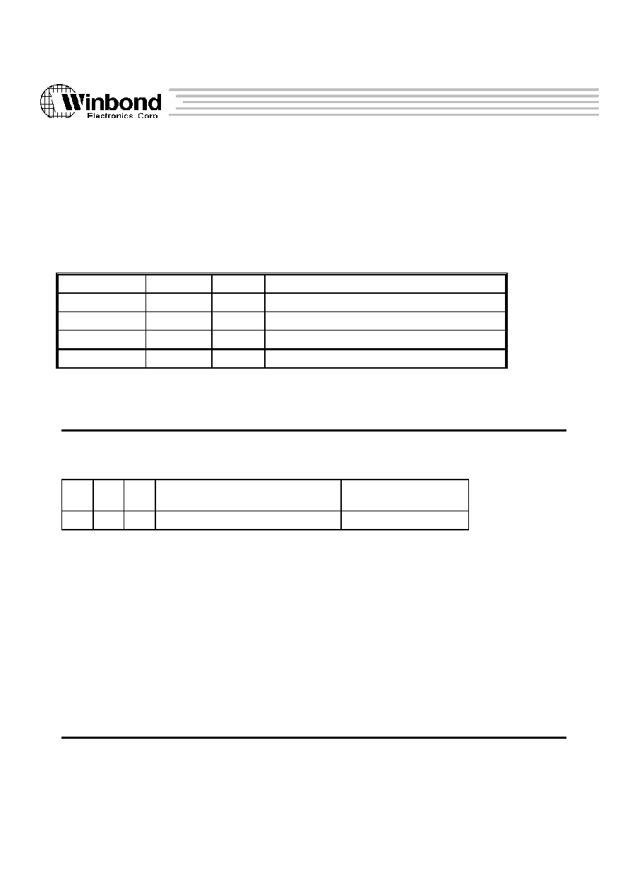
W90220F
73
Version 0.84
The above information is the exclusive intellectual property of Winbond Electroncs Corp. and shall not be dsiclosed or distributed or reproduced without permission from
Winbond.
5.2.7 TIMER REGISTERS
There are four registers included in the Timer. The IO address map is allocated from 0xf0000040 to 0xf0000043.
Table 5.2.7-1 Timer Register Map (IO base (BA) : 0xf0000000)
Port Addr.
Symbol
Access
Description
BA + 0x40
TCR1
R/W
Timer Control Register 1
BA + 0x41
TICR1
R/W
Timer Initial Control Register 1
BA + 0x42
TCR2
R/W
Timer Control Register 2
BA + 0x43
TICR2
R/W
Timer Initial Control Register 2
Timer Control Register1 (TCR1)
Port address : 0x00000040
Read/Write
Power-on Default : --
0
1
2
3
23
24 31
TI
CE
IE
Reserved
Pre-scale
Bit 0 Timer interrupt bit : The timer sets this bit to one to indicate that it has decremented to
zero. this bit remain one until software sets it to zero.
Bit1 Counter Enable bit : Setting the CE bit to one causes the timer to begin decrementing
Setting the CE bit to zero stops the timer.
Bit2 Interrupt Enable bit : When IE is set to one and the counter decrements to zero,
the timer asserts its interrupt signal to interrupt CPU.
Bit24_31 Pre-Scalar : A pre-scalar value can be used to divide the input clock.
W90220F
74
Version 0.84
The above information is the exclusive intellectual property of Winbond Electroncs Corp. and shall not be dsiclosed or distributed or reproduced without permission from
Winbond.
Timer Initial Control Register1 (TICR1)
Port address : 0xf0000041
Read/Write
Power-on Default : --
0
7
8
31
reserved
Timer Initial Count
Bit8_31 : A 24-bit register for the initial counter value.
Timer Control Register2 (TCR2)
Port address : 0xf0000042
Read/Write
Power-on Default : --
0
1
2
3
23
24 31
TI
CE
IE
Reserved
Pre-scale
Bit 0 Timer interrupt bit : The timer sets this bit to one to indicate that it has decremented
to zero. this bit remain one until software sets it to zero.
Bit1 Counter Enable bit : Setting the CE bit to one causes the timer to begin decrementing
Setting the CE bit to zero stops the timer.
Bit2 Interrupt Enable bit : When IE is set to one and the counter decrements to zero, the
timer asserts its interrupt signal to interrupt CPU.
Bit24_31 Pre-Scalar : A pre-scalar value can be used to divide the input clock.
Timer Initial Control Register1 (TICR2)
Port address : 0xf0000043
Read/Write
Power-on Default : --

W90220F
75
Version 0.84
The above information is the exclusive intellectual property of Winbond Electroncs Corp. and shall not be dsiclosed or distributed or reproduced without permission from
Winbond.
0
7
8
31
reserved
Timer Initial Count
Bit8_31 : A 24-bit register for the initial counter value.
Two 24-bit decrementing timers will be implemented, corresponding to the TCR1, TICR1 and TCR2, TICR2
independently. When the timers interrupt enable bit is set to one and the counter decrements to zero, the timer
will assert the associated interrupt signal. The interrupt signal will assert one of the 32 external interrupts
defined by the EI bits in the control register. When a timer reaches zero, the timer hardware reloads the
counter with the value from the timer initial count register and continues decrementing.

W90220F
76
Version 0.84
The above information is the exclusive intellectual property of Winbond Electroncs Corp. and shall not be dsiclosed or distributed or reproduced without permission from
Winbond.
6 ELECTRICAL SPECIFICATIONS
6.1 Absolute Maximum Ratings
Ambient temperature ....................................................................................................... 0
�
C ~ 70
�
C
Storage temperature ......................................................................................................... -40
�
C ~ 125
�
C
Voltage on any pin ........................................................................................................... Vss-0.5V ~ Vcc+0.5V
Power supply voltage ....................................................................................................... 7V
Injection current (latch-up testing) ................................................................................... 100mA
Operating power dissipation ............................................................................................. 30mA/Mhz
6.2 DC Specifications
(Normal test conditions : VDD5V = 5.0V+/- 5%, VDDi/VDDp/VDDl = 3.3V+/- 5%, TA = 0
�
C ~ 70
�
C
unless otherwise specified)
SYMBOL
PARAMETER
CONDITION
MIN
MAX
UNIT
VDD5V
Power Supply
4.75
5.25
V
VDDi/VDDp
Power Supply
3.14
3.46
V
VIL
Input Low Voltage
0.8
V
VIH
Input High Voltage
2.0
V
VOL
Output Low Voltage
IOUT = 2,4,8 mA
(*2)
VSS+ 0.4
V
VOH
Output High Voltage
IOUT = -1,2,4 mA
(*2)
2.4
V
ICC
Supply Current
Fcpu = 100Mhz
300
mA
IIH
Input High Current
VIN = 2.4 V
(*1)
10
�
A
IIL
Input Low Current
VIN = 0.4 V
(*1)
-10
10
�
A
IIHP
Input High Current (pull-up) VIN = 2.4 V
(*3)
-45
-15
�
A
IILP
Input Low Current (pull-up)
VIN = 0.4 V
(*3)
-10
�
A
Note *1 : Inpt leakage current (IIL, IIH) include those bi-directional pins which are in "input" mode (output
disable).
*2 : Pins of 4mA sink capability include :
ROMMEN#, DACK[0:1], CS[0:1], TC[0:1], DTR1#, RTS1#,

W90220F
77
Version 0.84
The above information is the exclusive intellectual property of Winbond Electroncs Corp. and shall not be dsiclosed or distributed or reproduced without permission from
Winbond.
SOUT1, SOUT2.
Pins of 6mA sink capability include :
RAS#[0:3], RCS#[0:3], ROM_OE#, ROM_RW#, IOR, IOW,
nAutoFd, nStrob, SelectIn, nInit, SDO, MD[0:31], DD[0:7],
PCICLK, SCLK, SYNC.
Pins of 8mA sink capability include :
CAS#[0:3], MA[0:11], WE#, PCIRST, GNT#[0:1], ED[0:7],
C/BE[0:3], PDA[0:31], STOP#, PERR#, TRDY#, DEVSEL#,
FRAME#, IRDY#, PPAR.
*3 : Inputs with internal pull-up resistor include : PREQ#[0:1], SERR#, INTA#, INTB#, INTC#, INTD#,
CTS1#, DSR1#, RI1#, DCD1#.
6.3 AC Specifications
6.3.1 Memory controller
Fig 6.3.1-1 : DRAM AC Timimg
PCLK
RAS3# - RAS0#
MA11 - MA0
CAS3# - CAS0#
MD31 - MD0
WE#
trv1
twv
tcv1
tav
tds tdh
trv2
tcv2
Symbol
Parameter
Min
Max
Unit
trv1
RAS# valid delay ref. to PCLK rising
ns
trv2
RAS# valid delay ref. to PCLK rising
ns
tcv1
CAS# valid delay ref. to PCLK rising
ns
tcv2
RAS# valid delay ref. to PCLK rising
ns
twv
WE# valid delay ref. to PCLK rising
ns
tds
Memory data setup time
ns
tdh
Memory data hold time
ns
tav
Memory address valid delay
ns
Fig 6..3.1-2 Flash ROM Write Timimg

W90220F
78
Version 0.84
The above information is the exclusive intellectual property of Winbond Electroncs Corp. and shall not be dsiclosed or distributed or reproduced without permission from
Winbond.
PCLK
RCS0# -
RCS3#
MA11 - MA0
ROMRW#
MD31 - MD0
ROMOE#
tas
tcs
twp
tds
tdh
Symbol
Parameter
Min
Max
Unit
tas
Address setup time
ns
tcs
Chip select setup time
ns
tds
Data setup time
ns
tdh
Data hold time
ns
twp
Flash ROM write pulse width
7
PCLK
Fig 6.3.1-3 ROM Read Timimg
PCLK
RCS0# -
RCS3#
MA11 - MA0
ROMRW#
MD31 - MD0
ROMOE#
tcs
tac
top
tds
tdh
Symbol
Parameter
Min
Max
Unit
tac
Access time
3
PCLK
tcs
Chip select setup tome
ns

W90220F
79
Version 0.84
The above information is the exclusive intellectual property of Winbond Electroncs Corp. and shall not be dsiclosed or distributed or reproduced without permission from
Winbond.
top
Output enable pulse
ns
tds
Data setup tome
ns
tdh
Data hold time
ns
7 PACKAGE DIMENSIONS
The W90220 is packaged in a 208-pin PQFP package. The following figure shows its mechanical
dimension
H
D
D
e
b
E H
E
y
A
A
Seating Plane
L
L
1
See Detail F
Detail F
c
1
A
2
1
52
53
104
105
156
157
208
1.Dimension D & E do not include interlead
flash.
2.Dimension b does not include dambar
protrusion/intrusion
3.Controlling dimension : Millimeter
4.General appearance spec. should be based
on final visual inspection spec.
.
0.10
0
10
10
0
0.004
1.30
0.70
30.90
30.90
0.50
30.60
30.60
0.30
30.30
30.30
0.051
0.028
1.217
1.217
0.020
1.205
1.205
0.012
1.193
1.193
0.50
28.13
28.13
0.25
0.25
3.35
3.68
28.00
28.00
3.23
27.87
27.87
0.10
0.15
3.10
0.10
1.107
1.107
0.010
0.010
0.132
0.145
1.102
1.102
0.127
0.020
1.097
1.097
0.004
0.006
0.122
0.004
Note:
Symbol
Min
Nom
Max
Max
Nom
Min
Dimension in inch
Dimension in mm
A
b
c
D
e
H
D
H
E
L
y
0
A
A
L
1
1
2
E
0.008
0.006
0.15
0.20
0.016
0.043
0.024
0.059
0.40
0.60
1.10
1.50