W963B6BBN
512K WORD
◊ 16 BIT LOW POWER PSEUDO SRAM
Publication Release Date: March 11, 2003
- 1 -
Revision A1
Table of Contents-
1. GENERAL DESCRIPTION.................................................................................................................. 3
2. FEATURES ......................................................................................................................................... 3
3. PRODUCT OPTIONS ......................................................................................................................... 3
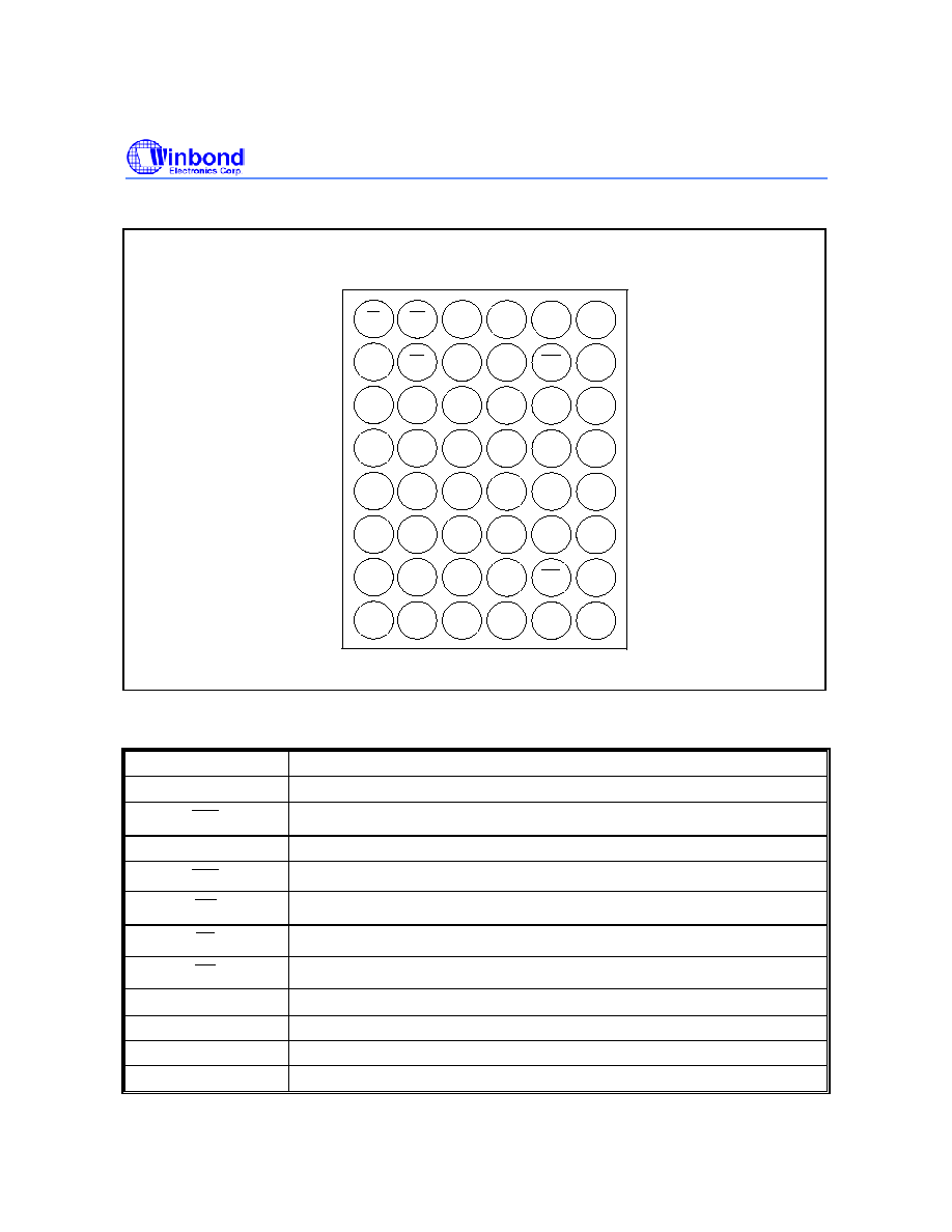
4. BALL CONFIGURATION .................................................................................................................... 4
5. Ball DESCRIPTION............................................................................................................................. 4
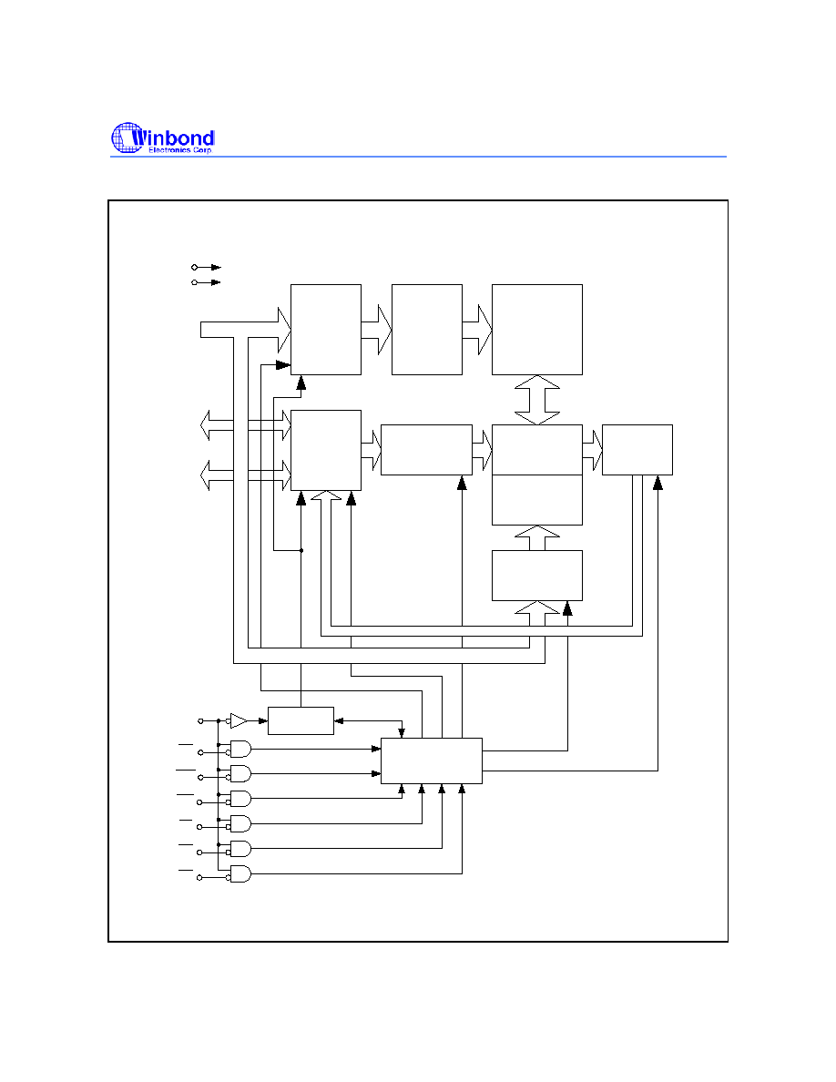
6. BLOCK DIAGRAM .............................................................................................................................. 5
7. FUNCTION TRUTH TABLE ................................................................................................................ 6
8. ELECTRICAL CHARACTERISTICS ................................................................................................... 7
Absolute Maximum Ratings .............................................................................................................. 7
Recommended Operating Conditions............................................................................................... 7
Capacitance ...................................................................................................................................... 8
DC Characteristics ............................................................................................................................ 8
AC Characteristics ............................................................................................................................ 9
Read Operation .........................................................................................................................................9
Write Operation .......................................................................................................................................11
Power Down and Power Down Program Parameters ..............................................................................13
Other Timing Parameters ........................................................................................................................13
AC Test Conditions
..............................................................................................................................13
9. TIMING WAVEFORMS ..................................................................................................................... 14
Read Timing #1 (
OE
Control Access)............................................................................................ 14
Read Timing #2 (
CE1
Control Access) .......................................................................................... 15
Read Timing #3 (Address Access after
OE
Control Access) ........................................................ 16
Read Timing #4 (Address Access after
CE1
Control Access)....................................................... 17
Write Timing #1 (
CE1
Control) ....................................................................................................... 18
Write Timing #2-1 ( WE Control, Single Write Operation) .............................................................. 19
Write Timing #2 ( WE
Control, Continuous Write Operation) ......................................................... 20
Read/Write Timing #1-1 (
CE1
Control)........................................................................................... 21

W963B6BBN
- 2 -
Read/Write Timing #1-2 (
CE1
Control)........................................................................................... 22
Read ( OE Control) / Write ( WE Control) Timing #2-1 .................................................................. 23
Read ( OE Control) / Write ( WE Control) Timing #2-2 .................................................................. 24
Power Down Program Timing ......................................................................................................... 25
Power Down Entry and Exit Timing................................................................................................. 25
Power-up Timing #1 ........................................................................................................................ 25
Power-up Timing #2 ........................................................................................................................ 26
Standby Entry Timing after Read or Write ...................................................................................... 26
10. PACKAGE DIMENSION.................................................................................................................. 27
TFBGA 48 Balls (6 x 8 mm^2, pitch 0.75 mm)................................................................................ 27
11. ORDERING INFORMATION........................................................................................................... 28
12. VERSION HISTORY ....................................................................................................................... 29

W963B6BBN
1. GENERAL DESCRIPTION
W963B6BBN is a 8M bits CMOS pseudo static random access memory (Pseudo SRAM), organized
as 512K words x 16 bits. Using advanced single transistor DRAM architecture and 0.175
µm process
technology; W963B6BBN delivers fast access cycle time and low power consumption. It is suitable for
mobile device application such as Cellular Phone and PDA, which high-density buffer is needed and
power dissipation is most concerned.
2. FEATURES
∑
Asynchronous SRAM interface
∑
Fast access cycle time:
- t
RC
= 70 nS (-70), 80 nS (-80)
∑
Low power consumption:
- I
DDA1
= 20 mA Max.
- I
DDS1
= 70
µA Max.
∑
Byte write control
∑
Power supply:
- V
DD
= +2.3V to +2.7V
∑
Temperature:
- T
A
= 0∞C to +70∞C
- T
A
= -25∞C to +85∞C (Extended temperature)
- T
A
= -40∞C to +85∞C (Industrial temperature)
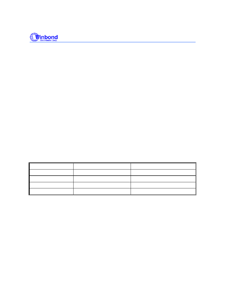
3. PRODUCT OPTIONS
PARAMETER W963B6BBN70
W963B6BBN80
t
RC
70 nS min.
80 nS Min.
I
DDS1
70
µA max.
70
µA Max.
I
DDA1
20 mA
20 mA
V
DD
2.3V to 2.7V
2.3V to 2.7V
Publication Release Date: March 11, 2003
- 3 -
Revision A1


