 | –≠–ª–µ–∫—Ç—Ä–æ–Ω–Ω—ã–π –∫–æ–º–ø–æ–Ω–µ–Ω—Ç: AH22AH22 | –°–∫–∞—á–∞—Ç—å:  PDF PDF  ZIP ZIP |
WJ Communications, Inc. ∑ Phone: 1-800-WJ1-4401 ∑ FAX: 408-577-6621 ∑ e-mail: sales@wj.com ∑ Web site: www.wj.com
October 2002
AH22
Product Description
The AH22 is a high dynamic range amplifier
targeting cable TV markets. The combination
of gain flatness, high linearity and bandwidth
makes it ideal for CATV distribution, cable
modem and laser diode driver applications.
The device uses two matched AH2 devices and
is ideal for operation in a push-pull configura-
tion to achieve high second order linearity. A
mature and reliable GaAs MESFET technolo-
gy is employed to maximize linearity at low
power dissipation. The package is thermally
enhanced in a SOIC-8 and all devices are
100% RF and DC tested.
Product Features
∑
50-860 MHz
∑
Contains 2 matched high-linearity
amplifiers in one package
∑
-69 dBc CTB
∑
-70 dBc CSO
∑
+23 dBm P1dB
∑
+41 dBm Output IP3
∑
+70 dBm Output IP2
∑
MTBF >100 Years
∑
+5 V Single Positive Supply
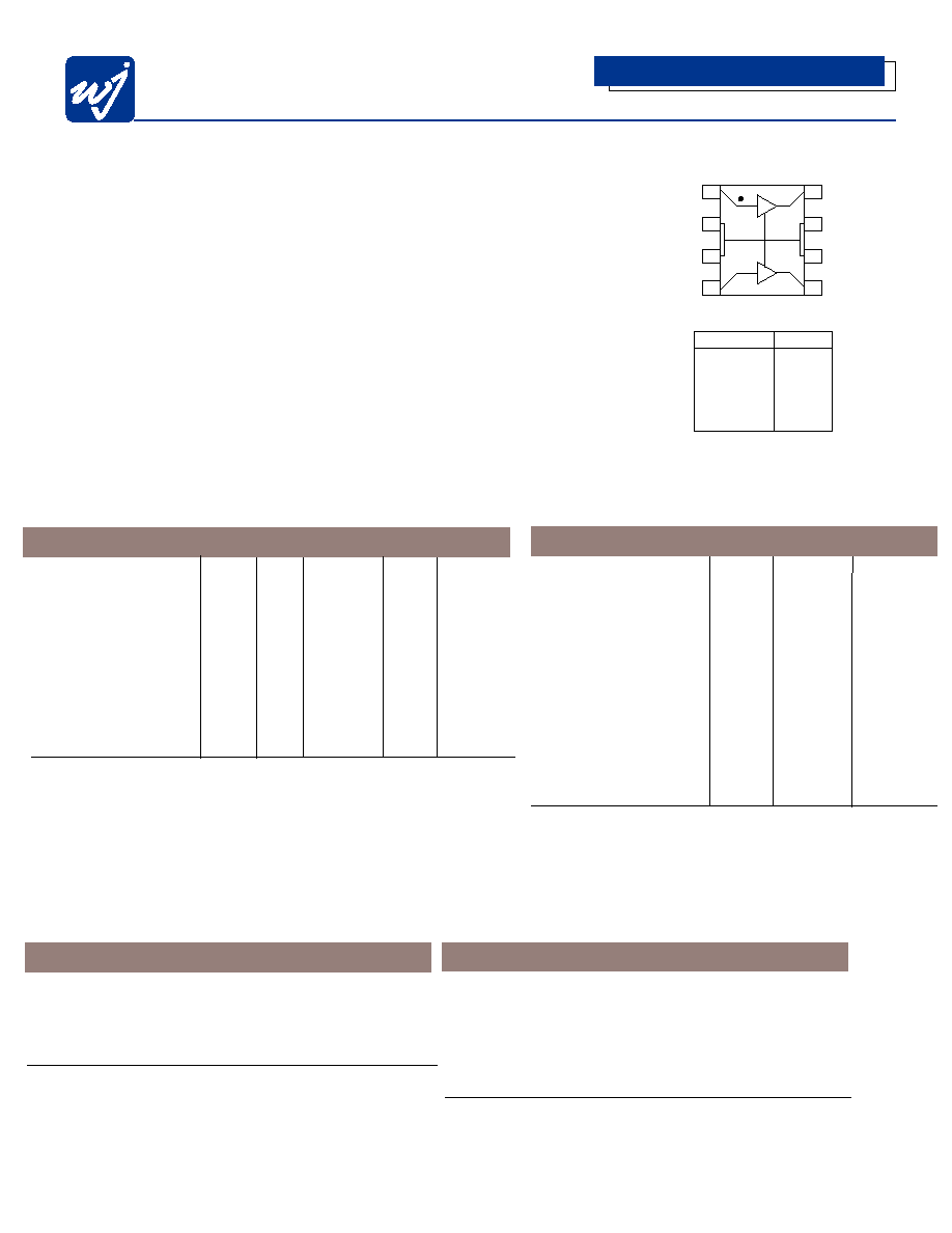
Functional Diagram
Absolute Maximum Ratings
Parameter
Rating
Operating Temperture
-40 to +85∞C
Storage Temperature
-40 to +125∞C
DC Voltage
+6.0 V
Input RF Power (continuous)
+13 dBm
Operation of this device above any of these parameters may cause permanent damage.
Ordering Information
Part No.
Description
AH22
High Dynamic Range CATV Amplifier
(Available in tape and reel)
AH22-PCB
Fully Assembled Application Circuit
50-860 MHz
AH22DUAL-PCB Fully Assembled Application Circuit,
Dual AH22
1
2
3
4
5
6
7
8
Function
Pin No.
1
4
2,3,6,7
5
Input 2
Input 1
Ground
Output/Bias2
Output/Bias1
8
High Dynamic Range CATV Amplifier
The Communications Edge
TM
Typical Specifications
Parameter
Units Typical Condition
Frequency MHz
50-860
S21 dB
11.2
50
MHz
S21
dB
10.6
860 MHz
S11
dB
-14.5
S22
dB
-15.1
Output IP3
dBm
+41
See Note 2
Output IP2
dBm
+70
P1dB dBm +23
Noise Figure dB
4.5
CTB dBc -69 See Note 5
CSO dBc -70 See Note 5
Xmod dBc -66 See Note 5
Test conditions unless otherwise noted:
4. T=25∞C, Vdd = 5.0V, and in a 75
application circuit.
5. 77 Channels, 50 - 550 MHz output power = +39 dBmV/channel, flat loaded.
Specifications
Parameter Units
Min. Typ. Max. Condition
Frequency Range
MHz
50-860
S21
dB
13
14.5
See Note 1
Output IP3
dBm
+37
+40 See Note 2
Output IP2
dBm
+47 See Note 1
P1dB
dBm
+20 See Note 1
Operating Current
mA
240
300 360
Supply Voltage
V
+5
Junction Temperature
∞C
160 See Note 3
Thermal Resistance
∞C/W
28
Test conditions unless otherwise noted:
1. Parameters reflect single-ended amplifier performance in a packaged device in a 75
system at
25∞C, Vdd = 5.0 V, and 800 MHz (there are 2 matched amplifiers in the AH22 package).
2. OIP3 measured with 2 tones at an output power of +8 dBm/tone separated by 10 MHz. The suppression on
the largest IM3 product is used to calculate the OIP3 using a 2:1 slope rule.
3. The maximum junction temperature ensures a minimum MTBF rating of 1 million hours of usage. Refer to
WJ Application Note "AH22 Temperature Effects on Reliability" for more information.
WJ Communications, Inc. ∑ Phone: 1-800-WJ1-4401 ∑ FAX: 408-577-6621 ∑ e-mail: sales@wj.com ∑ Web site: www.wj.com
October 2002
AH22
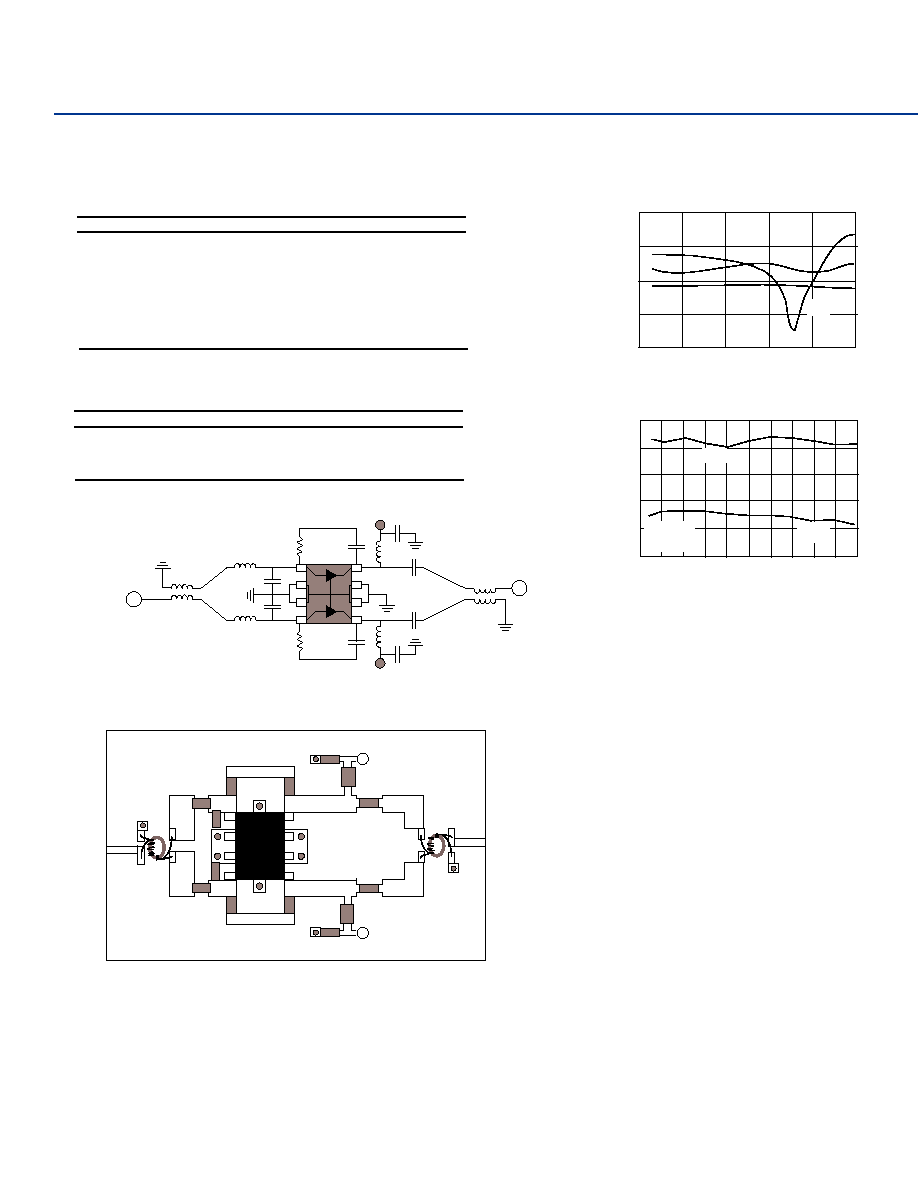
75
Push-Pull Circuit 50-860 MHz
L1
5.6nH
0603
C1
1.5pF
0603
T1
6 turns bifilar wire
around ferrite core
or
M/A Com ETC1-1-13
Core: TDK H5C2-T3.1-1.3-1.3
Wire: MWS B2383211
L2
5.6nH
R1
560
C3
100pF
C5
1000pF
C6
1000pF
L3
470nH
1008
L4
470nH
1008
T2
C7
1000pF
C4
100pF
C2
1.5pF
C8
1000pF
FR4 Board Layout (T = 28 Mils to ground plane)
Interior Trans. Lines Z = 37.5 Ohm
+5V
+5V
All components are of size 0603 unless otherwise noted.
L1
C1
L4
R1
T2
R2
C2
C8
T1
L2
AH22
C4
C3
L3
C6
C7
Typical Performance (75 Ohm System)
Frequency MHz 50 450 750 860
Magnitude S21 dB 11.2 10.9 10.9 10.6
Magnitude S11 dB -12.4 -12.2 -29.8 -14.6
Magnitude S22 dB -17.4 -12.9 -18.1 -12.4
OIP2 dBm +72 +70 +72 +70
OIP3 dBm +42 +43 +41 +40
Noise Figure dB 5.5 4.3 4.2 4.3
Bias Vdd = 5 V, Id = 300 mA
Note: Balun and board losses have not been extraced but typically account for 0.4 dB loss
midband and 1.1 dB loss at 860 MHz.
Multi-channel Measurements
Frequency 50-550 MHz
Schematic
CTB
CSO
XMOD
-69 dBc
-70 dBc
-66 dBc
Note: 77 Channels, +39 dBmV/Ch. output power, flat-loaded.
R2
560
RF OUT
RF IN
AH22
C5
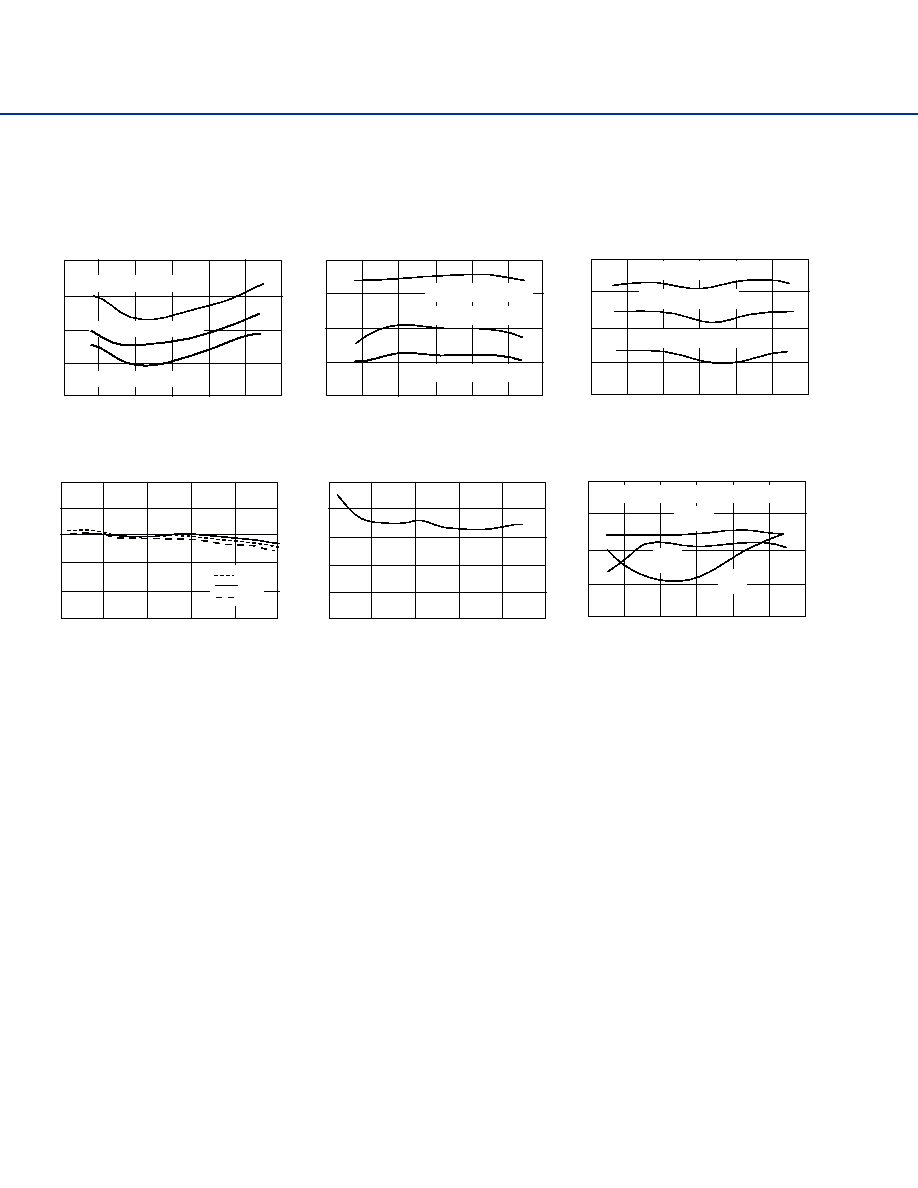
Performance Charts
Frequency (MHz)
0
200
400
600
800
1000
Input / Output Retrun Loss
and Isolation
0
-10
-20
-30
-40
Magnitude (dB)
Intercept Point (dBm)
Frequency (MHz)
0
100 200 300 400 500 600 700 800 900 1000
Linearity vs. Frequency
80
70
60
50
40
30
V = 5 V
I = 290 mA
OIP2
OIP3
S22
S12
S11
WJ Communications, Inc. ∑ Phone: 1-800-WJ1-4401 ∑ FAX: 408-577-6621 ∑ e-mail: sales@wj.com ∑ Web site: www.wj.com
October 2002
AH22
CTB (dBc)
Frequency (MHz)
0
100
200
300
400
500
600
XMOD (77 Channel Flat Loading)
CTB (77 Channel Flat Loading)
Xmod (dBc)
Frequency (MHz)
-50
-60
-70
-80
-90
-80
-70
-60
-50
Frequency (MHz)
0
100
200
300
400
600
CSO (77 Channel Flat Loading)
-50
-60
-70
-90
CSO (dBc)
-80
500
0
100
200
300
400
500
600
S21 (dB)
Frequency (MHz)
0
200
400
600
800
1000
Gain
13
11
9
7
5
15
Noise Figure (dB)
Frequency (MHz)
0
200
400
600
800
1000
Noise Figure
2
6
5
4
3
1
(dBc)
Frequency (MHz)
CTB, CSO, and, XMOD
-75
-60
-65
-70
-80
-40C
+85C
+25C
+44 dBmV output power
+39 dBmV output power
+44 dBmV output power
+34 dBmV output power
+34 dBmV output power
+39 dBmV output power
0
100
200
300
400
500
600
+39 dBmV output power
+34 dBmV output power
+44 dBmV output power
-90
77 Channel Flat Loading, +39 dBmV Ouput Power
XMOD
CTB
CSO
75
Push-Pull Circuit: 50-860 MHz
WJ Communications, Inc. ∑ Phone: 1-800-WJ1-4401 ∑ FAX: 408-577-6621 ∑ e-mail: sales@wj.com ∑ Web site: www.wj.com
October 2002
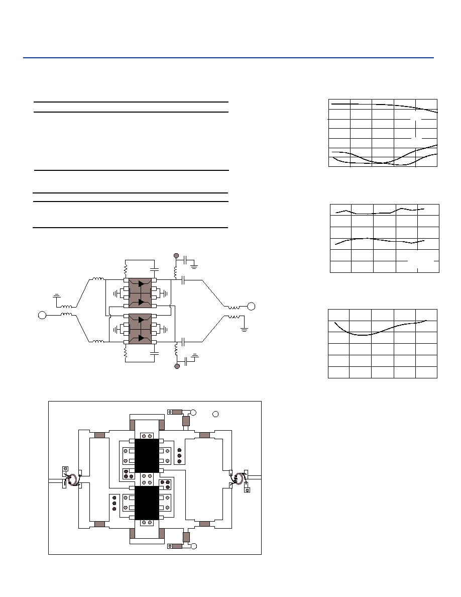
75
Dual Push-Pull Circuit: 50-860 MHz Performance
FR4 Board Layout (T = 28 Mils to ground plane)
AH22
AH22
AH22
AH22
DC
+5V
1000 pF
C3
560
R1
100 pF
C1
T1
T2
C5
1000 pF
C2
100 pF
3.3 nH
L1
3.3 nH
L2
C6
1000 pF
L3
470 nH
1008
560
R2
L4
470 nH
1008
DC
+5V
1000 pF
C4
All Components are of size 0603 unless otherwise noted.
L1
T1
R1
C1
C3
L3
C5
+5V
GND
L2
R2
C2
C4
L4
C6
T2
+5V
Core: TDK H5C2-T3.1-1.3-1.3
Wire: MWS B2383211
wire around
6 turns bifilar
ferrite core
or
MaCOM
ETCI-1-13
Surface Mount
balun
AH22
Typical Performance (75 Ohm System)
Frequency MHz 50 450 750 860
Magnitude S21 dB 12.9 12.3 11.3 10.5
Magnitude S11 dB -13.3 -15.6 -13.1 -10.2
Magnitude S22 dB -12.5 -16.6 -17.2 -14.8
OIP2 dBm +73 +72 +75 +76
OIP3 dBm +45 +49 +46 +47
Bias Vdd = 5 V, Id = 600 mA
Schematic
Note: Balun and board losses have not been extracted but typically account for 0.4 dB loss
midband and 1.1 dB loss at 860 MHz.
Noise Figure
dB
4.7 4.2 4.8 5.1
Multi-channel Measurements
Frequency 50-550 MHz
CTB -73 dBc
CSO -74 dBc
XMOD -68 dBc
Note: 77 Channels, +39 dBmV/Ch. Output power, flat-loaded
S-Parameters
Frequency (MHz)
Magnitude (dB)
15
10
5
0
-5
-10
-20
-15
0
200
400
600
800
1000
Linearity vs. Frequency
Frequency (MHz)
Intercept Point (dBm)
80
70
60
40
50
30
20
0
200
400
600
800
1000
OIP3
OIP2
V = 5 V
I = 600 mA
Noise Figure
Frequency (MHz)
Noise Figure (dB)
6
5
4
2
3
1
0
0
200
400
600
800
1000
S21
S22
S11
AH22
WJ Communications, Inc. ∑ Phone: 1-800-WJ1-4401 ∑ FAX: 408-577-6621 ∑ e-mail: sales@wj.com ∑ Web site: www.wj.com
October 2002
AH22
Typical Device Data
S-Parameters of a single-ended unmatched amplifier de-embedded to device leads. (Vdd = +5 V, Ids = 150
mA, T = 22∞C, Z = 75
) There are two matched amplifiers in an AH22 package.
Freq. (MHz)
S11 (dB)
S11 (Ang)
S21 (dB)
S21 (Ang)
S12 (dB)
S12 (Ang)
S22 (dB) S22 (Ang)
10
-6.56
-1.06
16.19
179.34
-26.86 -0.24 -11.34 -2.97
50
-6.57
-5.11
16.21
176.71
-26.79
0.98
-11.38
-3.37
100
-6.58
-10.53
16.20
173.44
-26.75
2.07
-11.37
-6.44
150
-6.59
-15.58
16.15
170.06
-26.68
2.99
-11.42
-9.98
200
-6.56
-20.57
16.11
166.96
-26.64
3.89
-11.47
-12.90
250
-6.60
-25.69
16.06
164.01
-26.51
5.01
-11.59
-15.76
300
-6.62
-30.46
16.03
160.82
-26.35
5.50
-11.61
-18.81
350
-6.56
-35.67
15.98
157.75
-26.17
6.15
-11.65
-21.96
400
-6.55
-40.48
15.94
154.71
-26.01
7.06
-11.70
-24.72
450
-6.53
-45.36
15.86
151.43
-25.87
6.72
-11.77
-27.85
500
-6.51
-50.19
15.78
148.50
-25.68
6.94
-11.89
-31.18
550
-6.46
-54.97
15.70
145.54
-25.45
7.07
-11.92
-34.36
600
-6.42
-59.85
15.63
142.41
-25.25
7.15
-12.08
-37.39
650
-6.39
-64.24
15.51
139.38
-25.09
6.43
-12.13
-40.47
700
-6.36
-69.05
15.39
136.57
-24.93
6.19
-12.26
-43.92
750
-6.29
-73.42
15.32
133.72
-24.76
6.22
-12.41
-47.02
800
-6.27
-77.91
15.20
130.69
-24.53
5.32
-12.51
-50.28
850
-6.16
-82.11
15.07
128.05
-24.47
4.72
-12.64
-53.77
900
-6.10
-86.56
14.98
125.45
-24.45
4.23
-12.78
-56.88
950
-6.07
-90.56
14.86
122.44
-24.10
3.18
-12.91
-60.02
1000
-5.98
-94.80
14.73
120.01
-23.97
2.44
-13.06
-63.45
Specifications and information are subject to change without notice.
-95
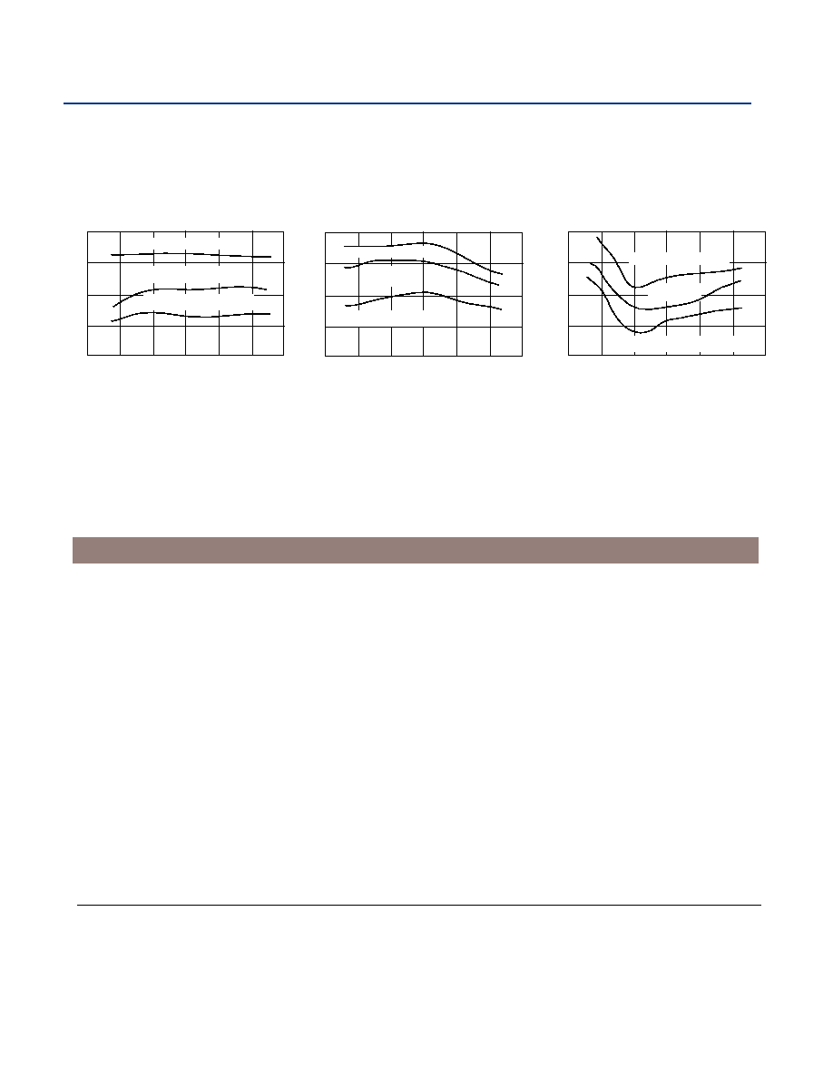
CTB (77 Channel Flat Loading)
Frequency (MHz)
CTB (dBc)
-55
-65
-75
0
100
200
300
400
600
500
-85
+44 dBmV output power
+39 dBmV output power
+34 dBmV output power
-95
XMOD (77 Channel Flat Loading)
Frequency (MHz)
XMOD (dBc)
-55
-65
-75
0
100
200
300
400
600
500
-85
-95
CSO (77 Channel Flat Loading)
Frequency (MHz)
CSO (dBc)
-55
-65
-75
0
100
200
300
400
600
500
-85
+44 dBmV output power
+39 dBmV
output power
+34 dBmV output power
+44 dBmV output power
+39 dBmV
output power
+34 dBmV output power
75
Dual Push-Pull Circuit: 50-860 MHz